Sélection de la langue

Search

Sommaire du brevet 1308772 

Énoncé de désistement de responsabilité concernant l'information provenant de tiers

Une partie des informations de ce site Web a été fournie par des sources externes. Le gouvernement du Canada n'assume aucune responsabilité concernant la précision, l'actualité ou la fiabilité des informations fournies par les sources externes. Les utilisateurs qui désirent employer cette information devraient consulter directement la source des informations. Le contenu fourni par les sources externes n'est pas assujetti aux exigences sur les langues officielles, la protection des renseignements personnels et l'accessibilité.

Disponibilité de l'Abrégé et des Revendications

L'apparition de différences dans le texte et l'image des Revendications et de l'Abrégé dépend du moment auquel le document est publié. Les textes des Revendications et de l'Abrégé sont affichés :

  • lorsque la demande peut être examinée par le public;
  • lorsque le brevet est émis (délivrance).
(12) Brevet: (11) CA 1308772
(21) Numéro de la demande: 1308772
(54) Titre français: LUMINAIRES FLUORESCENTS
(54) Titre anglais: FLUORESCENT LIGHTS
Statut: Périmé et au-delà du délai pour l’annulation
Données bibliographiques
(51) Classification internationale des brevets (CIB):
  • H05B 41/23 (2006.01)
(72) Inventeurs :
  • YUEN, TO (Hong Kong, Chine)
  • CHAN, BONG (Hong Kong, Chine)
  • POON, CHIU YEUNG (Hong Kong, Chine)
  • LUI, CHI MAN (Hong Kong, Chine)
(73) Titulaires :
  • TO YUEN
  • BONG CHAN
  • CHIU YEUNG POON
  • CHI MAN LUI
(71) Demandeurs :
(74) Agent: SMART & BIGGAR LP
(74) Co-agent:
(45) Délivré: 1992-10-13
(22) Date de dépôt: 1987-09-17
Licence disponible: S.O.
Cédé au domaine public: S.O.
(25) Langue des documents déposés: Anglais

Traité de coopération en matière de brevets (PCT): Non

(30) Données de priorité de la demande: S.O.

Abrégés

Abrégé anglais


A B S T R A C T
A fluorescent lamp system in which an inductor
(12) is connected in series with the cathodes (4, 6) of a
gas discharge tube (2). Separate connections (14, 16) are
tapped from the inductor (12) and also coupled to the
cathodes of the tube. One connection includes a capacitor
(18). Upon connection of an AC electrical supply a voltage
builds up and discharges from the capacitor (18) at one
cathode (4) as a surge voltage builds up at the other
cathode (6). The resulting peak voltage at the cathodes is
sufficient to immediately strike an arc in the tube (2).

Revendications

Note : Les revendications sont présentées dans la langue officielle dans laquelle elles ont été soumises.


27876-1
THE EMBODIMENTS OF THE INVENTION IN WHICH AN EXCLUSIVE
PROPERTY OR PRIVILEGE IS CLAIMED ARE DEFINED AS FOLLOWS:
1. A fluorescent lamp system comprising a gas discharge
tube with cathodes at either end thereof; a ballast having an
inductor connected in series with the cathodes of the discharge
tube and separate connections to the discharge tube tapped from
the inductor and also coupled to the cathodes of the tube, one of
the connections including a capacitor such that upon connection to
an AC electrical supply a voltage is built up in the capacitor for
discharge at one cathode of the discharge tube as a surge voltage
is generated at the other cathode to establish a peak voltage
sufficient to strike an arc in the tube.
2. A system according to Claim 1 wherein the disposition of
the tapped connections on the inductor is adjustable.
3. A system according to Claim 1 or Claim 2 wherein the
inductor and tapped connections including the capacitor are in-
cluded in a single ballast unit.

Description

Note : Les descriptions sont présentées dans la langue officielle dans laquelle elles ont été soumises.

9~ r 1 308772
- 1
FLUORESCENT LIGHTS
S This invention relates fluorescent lamp~ in which
a gas discharge tube i3 adapted to emit light by the
stimulation of vapour within the tube. The operation of a
gas discharge tube to emit light in this way is well known.
Known fluorescent lamp systems use a ballast
coupled wlth a starter switch in order to generate a
sufficient voltage to strike an arc in the ga~ discharge
tube to initiate stimulation of tho vapour therein. Once
initiated, the stimulation of the vapour can be sustained
by a lower voltage. Thi~ known system normally results in
the tube flashing a few tLmes before emitting continuous
light, which flashing is itself disadvantageous as it
reduces the effective life of the tube. A variety of
ball4st designs have been proposed, each having advantages
and disadvantages. However, each has a common problem in
~0 that it fails to operate at all when the supply voltage
drops substantially, for example, by around 20S. This
renders the system unsuitable for regions where a reliable
mains suppIy is not available.
~ A system has been proposed which does not require
; 25 the use of a starter switch, and in which upon connection
of the mains supply, the light emitted from the tube grows
~::
. .
~ . .
.

1 30877?
~2~ 27876~1
gradually, and without flashing. While this system avoid~ the
reduced life of the tube consequential upon flashing, the lamp
will nevertheless fail to operate upon a substantial fall in
the supply voltage.
According to the present invention, a ballast is used
which comprises an inductor connected in series with the gas
discharge tube, but separate connections to the tube are tapped
from an intermediate length of the inductor. One of these
connections includes a capacitor whereby upon connection of the
mains supply, a voltage is built up in the capacitor for dis~
charge at one cathode of the tube to strike an arc therein.
Once struck, the arc is sustained by a lower voltage which is
preserved across the tube through the other connection.
By appropriate selection of the number of turns in
the inductor, the capacitor, and the tapped connections from
the inductor, a lamp according to the invention can be adapted
to operate over a broad range of supply voltages, for example,
from as low as 140 volts to as high as 250 volt~. In a typical
lamp according to the invention, a 20 to 40 watt fluorescent
tube is connected to a mains supply through a ballast compris~
ing an inductor of around 1,000 turns, the tapped connections
being spaced by around 600 turns adjacent one end of the coil.
In accordance with the present invention, there is
provided a fluorescent lamp system comprising a gas discharge
tube with cathodes at either end thereof; a ballast having an
inductor connected in series with the cathodes of the discharge

1 3Q8772
-2a~ 27876~1
tube and separate connections to the discharge tube tapped from
the inductor and also coupled to the cathodes of the tube, one
of the connections including a capacitor such that upon
connection to an AC electrical supply a voltage is built up in
the capacitor for discharge at one cathode of the discharge
tube as a surge voltage is generated at the other cathode to
establish a peak voltage sufficient to strike an arc in the
tube.
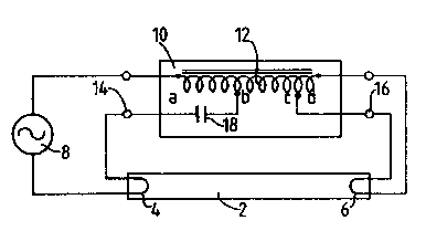
An embodiment of the invention will now be described
by way of example and with reference to the

1 308772
/ - 3 -
/ accompanying schematic drawing, which shows a circuit
incorporating a fluorescent gas discharge tube for coupling
to an AC mains supply,
The circuit illustrated shows a discharge tube 2
S having two cathodes 4, 6 connected via a switch ~not shown)
to~an AC mains supply 8 through a ballast 10. The ballast
10 comprises an inductor coil 12 connected in series with
the tube 2, and has two connections 14 and 16 ~apped
therefrom. Connection 14 is tapped to the inductor coil
through a capacitor 18, the connections 14 and 16 are
themselves also coupled to the cathode~ 4 and 6 of the tube
2.
The circuit shown i9 suitable for illuminating a
20 to 40 watt fluore~cent tube from an AC mains supply of
200 volts. The inductor con~ists of a coil of 1,005 turns
around a 6.5 sq.cm. core with a 0.26 mm. gap on the
magnetic path. The tappings _ and c are spaced by 600
turns, equivalent an inductance of 0.4S Henries. The
tapping b is ~paced from the end a of the coil by 400 turns
(approximately 0.22 Henries~ and tapping c is ~paced from
the other end d of the coil by 5 turns. The capacitance of
the capacitor 18 is 7.6,ufd. The dispo~ition of the
tappings a and b may be adjusted for different mains supply
voltages.
25In the arrangement shown, the connection of the
200 volt AC supply will generate a peak voltage of around

1 3~8~
400 volt~ at connection 14, and a surge voltage as a pip of
around 800 volts at connection 16. These voltages are in
phase and the resulting peak voltage acros~ the cathodes of
the tube 2 will be higher than 1,200 volts, resulting in
the immediate striking of the arc therein. Once the arc is
struck, the voltage across the cathodes will drop to around
100 volts, RMS, su~taining the arc and maintaining ths tube
illuminated.
It will be appreciated that in the event of the
mains supply falling by 20%, a surge voltage will be
generated across the cathodes 4 and 6 in excess of 1,000
volts, qu~te Qufficient to ~trike an arc in the tube.
Further, ~n each ca~e, the arc will be ~truck immediately
the circuit is connected to the mains supply, and
preliminary fla~hing i~ avoided.
Fluorescent lamps adapted according to the
invention can be effectively used in regions where the AC
mains supply varie~ over a relatively wide range. The
sy~tsm illu~trated can be connected to supply voltages
which vary between 140 and 250 voltQ, and rsmain effective,
whereas comparable previous systems would cease to function
at voltages below around 170 volts. It will be appreciated
also that fluorescent lamp~ may be adapted according to the
invention to operate in conjunction with ~upply voltages
other than those referred above.

Dessin représentatif
Une figure unique qui représente un dessin illustrant l'invention.
États administratifs

2024-08-01 : Dans le cadre de la transition vers les Brevets de nouvelle génération (BNG), la base de données sur les brevets canadiens (BDBC) contient désormais un Historique d'événement plus détaillé, qui reproduit le Journal des événements de notre nouvelle solution interne.

Veuillez noter que les événements débutant par « Inactive : » se réfèrent à des événements qui ne sont plus utilisés dans notre nouvelle solution interne.

Pour une meilleure compréhension de l'état de la demande ou brevet qui figure sur cette page, la rubrique Mise en garde , et les descriptions de Brevet , Historique d'événement , Taxes périodiques et Historique des paiements devraient être consultées.

Historique d'événement

Description Date
Le délai pour l'annulation est expiré 1999-10-13
Lettre envoyée 1998-10-13
Accordé par délivrance 1992-10-13

Historique d'abandonnement

Il n'y a pas d'historique d'abandonnement

Historique des taxes

Type de taxes Anniversaire Échéance Date payée
TM (catégorie 1, 5e anniv.) - petite 1997-10-14 1997-10-08
Annulation de la péremption réputée 1997-10-14 1997-10-08
Titulaires au dossier

Les titulaires actuels et antérieures au dossier sont affichés en ordre alphabétique.

Titulaires actuels au dossier
TO YUEN
BONG CHAN
CHIU YEUNG POON
CHI MAN LUI
Titulaires antérieures au dossier
S.O.
Les propriétaires antérieurs qui ne figurent pas dans la liste des « Propriétaires au dossier » apparaîtront dans d'autres documents au dossier.
Documents

Pour visionner les fichiers sélectionnés, entrer le code reCAPTCHA :


Pour visualiser une image, cliquer sur un lien dans la colonne description du document. Pour télécharger l'image (les images), cliquer l'une ou plusieurs cases à cocher dans la première colonne et ensuite cliquer sur le bouton "Télécharger sélection en format PDF (archive Zip)" ou le bouton "Télécharger sélection (en un fichier PDF fusionné)".

Liste des documents de brevet publiés et non publiés sur la BDBC .

Si vous avez des difficultés à accéder au contenu, veuillez communiquer avec le Centre de services à la clientèle au 1-866-997-1936, ou envoyer un courriel au Centre de service à la clientèle de l'OPIC.


Description du
Document 
Date
(aaaa-mm-jj) 
Nombre de pages   Taille de l'image (Ko) 
Page couverture 1993-11-04 1 10
Abrégé 1993-11-04 1 16
Revendications 1993-11-04 1 26
Dessins 1993-11-04 1 9
Description 1993-11-04 5 140
Dessin représentatif 2001-01-11 1 6
Avis concernant la taxe de maintien 1998-11-10 1 178
Taxes 1996-07-24 1 46
Taxes 1994-09-13 1 36
Taxes 1995-09-22 1 33