Note : Les descriptions sont présentées dans la langue officielle dans laquelle elles ont été soumises.
-
1308~395
SHIFT LINKAGE FOR MARINE
PROPULSION DEVICE
BACKGROUND OF THE INVENTION
The invention relates generally to
marine propulsion devices including reversing
transmissions and to remote operation of such
reversing transmissions by a push-pull cable.
Remote actuation of a marine propulsion
reversing transmission commonly involves operation of
a remote single lever control to displace the inner
core of a push-pull cable through a distance which is
often in excess of the distance actually required at
the marine propulsion device for shifting operation.
Such over-stroking places unnecessary heavy loading
on the push-pull cable in some circumstances.
In the past, attempts have been made to
overcome this problem by interposing a spring in the
operating linkage. However, use of such a spring can
cause delay in shift timing, insufficient load to
guarantee shifting, excessive loading after shifting,
or over-shooting neutral if the a neutral detent is
not strong enough.
Prior ignition interruption mechanisms
were actuated when shift loads were greater than a
pre-determined amount. Such prior mechanisms were
not always as effective as desired.
`-` 1308995
The arrangements disclosed hereinafter
are intended to overcome the foregoing problems.
Attention is direct to the following
U.S. patents:
3,481,223 D. A. Fraser December 2, 1969
4,215,596 L. C. Long August 5, 1980
4,262,622 Dretzka, et al. April 21, 1981
4,403,970 Dretzka, et al. September 13, 1983
4,432,734 Bland, et al. February 21, 1984
4,525,149 Broughton, et al. June 25, 1985
SUMMARY OF THE INVENTION
The invention provides a marine
propulsion device comprising a transmission supported
on the marine propulsion device and including a
clutch member movable between a neutral position and
a drive position, a shift lever supported on the
marine propulsion device by a pivotal mounting and
connected to the clutch member to effect movement of
the clutch member in response to movement of the
shift lever, and cam and follower means adapted to be
connected to a remotely actuated link and connected
to the shift lever for displacing the shift lever to
effect movement of the clutch member, and for
permitting over-travel of the link without displacing
13~8~95
the shift lever after shift lever movement effecting
movement of the clutch member to the drive position.
The invention also provides a marine propulsion
device comprising a transmission supported on the marine
propulsion device and including a clutch member movable
between a neutral position and a drive position, a shift
lever supported on the marine propulsion device by a pivotal
mounting and connected to the clutch member to effect
movement of the clutch member in response to movement of the
shift lever, and cam and follower means adapted to be
connected to a remotely actuated link and connected to the
shift lever for displacing the shift lever to effect
movement of the clutch member, and for permitting
over-travel of the link without displacing the shift lever
after shift lever movement effecting movement of the clutch
member to the drive position, which cam and follower means
comprises a shift plate movably supported on the marine
propulsion device by a pivot mounting and adapted for
connection to the remotely actuated link, one of the shift
lever and the shift plate having therein a cam slot
including a clutch actuating portion having opposite ends,
which cam slot is located at a radial distance from the
pivotal mounting of the one of the shift lever and the shift
plate, which radial distance increases from one of the ends
of the clutch actuating portion to the other of the ends of
the clutch actuating portion, which cam slot also includes a
dwell portion extending from one of the ends of the clutch
actuating portion at a uniform radius from the
-3-
-~ 13Q8995
pivotal mounting of the one of the shift lever and the shift
plate, and a follower extending from the other of the shift
lever and the shift plate and received in the cam slot.
The invention also provides a marine propulsion
device comprising a transmission supported on the marine
propulsion device and including a clutch member movable
between a neutral position, a drive position, and another
drive position, a shift lever supported on the marine
propulsion device by a pivotal mounting and connected to the
clutch member to effect movement of the clutch member in
response to movement of the shift lever, and cam and
follower means adapted to be connected to a remotely
actuated link and connected to the shift lever for
displacing the shift lever to effect movement of the clutch
member, and for permitting over-travel of the link without
displacing the shift lever after shift lever movement
effecting movement of the clutch member to the drive
position, which cam and follower means comprises a shift
plate movably supported on the marine propulsion device by a
pivot mounting and adapted for connection to the remotely
actuated link, one of the shift lever and the shift plate
having therein a cam slot including a central portion with a
pair of opposite ends, which cam slot is located at a radial
distance from the pivotal mounting of the one of the shift
lever and the shift plate, which radial distance increases
from one of the ends to the other of the ends, which cam
slot also includes end portions respectively extending from
the ends of the central portion at respectively uniform
-3A-
~'
13Q8995
radii from the pivotal mounting of the one of the shift
lever and the shift plate, and a follower extending from the
other of the shift lever and the shift plate and received in
the cam slot.
The invention also provides a marine propulsion
device comprising a transmission supported on the marine
propulsion device and including a clutch member movable
between a neutral position and a drive position, a shift
'ever supported on the marine propulsion device by a pivotal
mounting and connected to the clutch member to effect
movement of the clutch member in response to movement of the
shift lever, and cam and follower means adapted to be
connected to a remotely actuated link and connected to the
shift lever for displacing the shift lever to effect
movement of the clutch member, and for permitting
over-travel of the link without displacing the shift lever
after shift lever movement effecting movement of the clutch
member to the drive position, and for temporarily disabling
engine ignition at the time of clutch member movement from
the drive position.
The invention also includes a marine propulsion
device comprising a transmission supported on said marine
propulsion device and including a clutch member movable
between a neutral position and two drive positions located
respectively on opposite sides of the neutral position, a
shift lever pivotally supported on the marine propulsion
device and connected to the clutch member to effect movement
-3B-
1308995
of the clutch member in response to movement of the
shift the lever, which shift lever has thereon a
follower, a shift plate pivotally supported on the
marine propulsion device and adapted for connection
to a remotely actuated link to e~fect pivotal
movement of the shift plate in response to movement
of the link, which shift plate has therein a
transmission actuating cam slot receiving the
follower and including a central portion with a pair
of opposite ends, which transmission actuating cam
slot is located at a radial distance from the pivotal
support of said shift plate, which radial distance
increases from one of said cam slot central portion
ends to the other of said cam slot central portions
ends, said transmission actuating cam slot also
including end portions respectively extending from
the ends of the central portion at a uniform radius
from the pivotal support of the shift plate, a second
plate pivotally mounted on the shift plate and having
therein an ignition interrupting cam slot receiving
the follower, which ignition interrupting cam slot
includes a central portion with a pair of opposite
ends, and end portions respectively extending from
the ends of the central portion, which central
portions and which end portions of the transmission
actuating cam slot and of the ignition interrupting
cam slot are of generally identical size and shape
and are located in alignment when the clutch member
130899S
is in the drive positions, which ignition
interrupting cam slot also include first and second
opposed side edges, which ~irst side edge has therein
a recess adjacent the juncture of the central portion
and one of the end portions, and which second side
edge has therein a recess adjacent the juncture of
the central portion and the other of the end
portions, and a switch mounted on one of the shift
plate and the second plate and operable, when
actuated, to interrupt engine ignition, and an
actuator engagable with the switch for actuation
thereof to interrupt engine ignition on the other of
the shift plate and the second plate. . .
The invention also provides a linkage
adapted for use with a marine propulsion device
comprising an engine and a transmission including a-
clutch member movable between a neutral position a,nd
a drive position, which linkage comprises a first
member pivotally mounted on a support and movable in
coordinated relation to clutch member movement, a
second member pivotally mounted on the first member,
switch means adapted for interrupting engine
ignition, which switch means is mounted on one of the
first and second members, an actuator engagable with
tne switch means for actuation thereof to interrupt
engine ignition, which actuator is located on the
other of the first and second members and is operable
to actuate the switch means to interrupt engine
--5--
13~8995
ignition in response to relative displacement between the
first and second members, and cam and slot means for
actuating the switch means at the time of clutch member
movement from the drive position, said cam and slot means
including a cam slot on one of the first and second members,
and a follower extending from the other of the first and
second members into the cam slot for displacing the first
and second members relative to each other in response to
first member pivotal movement.
The invention also provides a marine propulsion
device comprising a transmission supported on the marine
propulsion device and including a clutch member movable
between a neutral position and a drive position, a shift
lever supported on the marine propulsion device by a pivotal
mounting and connected to the clutch member to effect
movement of the clutch member in response to movement of the
shift lever, and cam slot and follower means adapted to be
connected to a remotely actuated link and connected to the
shift lever for displacing the shift lever to effect
movement of the clutch member, and for permitting
over-travel of the link without displacing the shift lever
after shift lever movement effecting movement of the clutch
member to the drive position.
The invention also provides a marine propulsion
device comprising a transmission supported on the marine
propulsion device and including a clutch member movable
between a neutral position and a drive position, a shift
lever supported on the marine propulsion device by a pivotal
mounting and connected to the clutch member to effect
-6-
13~)8995
movement of the clutch member in response to movement of the
shift lever, a shift member supported on the marine
propulsion device by a pivotal mounting and adapted to be
connected to a remotely actuated link, and cam and follower
means on the shift lever and on the shift plate for
displacing the shift lever to effect movement of the clutch
member in response to shift plate movement incident to
movement of the actuating link, and for permitting
over-travel of the link without displacing the shift lever
after shift lever movement effecting movement of the clutch
member to the drive position.
Other features and advantages of the invention
will become apparent to those skilled in the art upon review
of the following detailed description, claims, and drawings.
THE DRAWINGS
Figure 1 is a side elevational view of a marine
propulsion device embodying various of the features of the
invention.
Figure 2 is an enlarged fragmentary view of
various of the components which are shown in Figure 1 and
which are located in a neutral condition.
Figure 3 is an end view kaken along line 3--3
of Figure 2.
Figure 4 is a view similar to Figure 2 showing
the components located in one drive condition.
__~ -6A-
- ~308995
Figure 5 is a view similar to Figure 2
showing the components located in another drive
condition.
Figure 6 is a view similar to Figure 2
illustrating the components during movement out of
the one drive condition.
Figure 7 is a view similar to Figure 2
illustrating the components during movement out of
the other drive condition.
Before one embodiment of the invention
is explained in detail, it is to be understood that
the invention is not limited in its application to
the details of construction and the arrangements of
components set forth in the following description or
illustrated in the drawings. The invention is
capable of other embodiments and of being practiced
or being carried out in various ways. Also, it is to
be understood that the phraseology and terminology
used herein is for the purpose of description and
should not be regarded as limiting.
GENERAL DESCRIPTION
Shown in Figure 1 is a marine
propulsion device 11 which can be either a stern
drive unit or an outboard motor and which is in the
form of an outboard motor.
1308995
The marine propulsion device includes a
propulsion unit 13 and means 15 connected to the
propulsion unit and adapted for mounting the
propulsion unit 13 from the transom (not shown) of a
boat for tilting movement in a vertical plane and for
steering movement in a horizontal plane. The
propulsion unit 13 includes a power head 17 which
comprises an internal combustion engine 19 having a
crankshaft (not shown) and which is mounted on a
lower unit 21 including an upper driveshaft housing
23 and a lower gear case 25.
Extending in the gearcase 25 is a
propeller shaft 31 which carries a propeller 33 and
which is connected to a driveshaft 35 by a reversing
clutch or transmission 37. The driveshaft 35 extends
through the driveshaft housing 23 and, at its upper
end, is drivingly connected to the engine crankshaft.
The reversing transmission 37 includes
a drive pinion 39 fixed to the lower end of the
driveshaft 35 and in meshing engagement with a pair
of spaced counter rotating bevel gears 41 and 43
mounted in co-axial relation to the propeller shaft
31. A dog or clutch member 45 is splined to the
propeller shaft 31 and is shiftable axially of the
propeller shaft between a central or neutral position
out of driving engagement with the bevel gears 41 and
43, a forward drive position located in axially
spaced relation in one direction from the neutral
13~89gS
position and in driving engagement with one of the
bevel gears 41 and 43, and a rearward drive position
located in axially spaced relation in the other
direction from the neutral position and in driving
engagement with the other one of the bevel gears 41
and 43.
Means are provided in the propulsion
unit for displacing the clutch member or dog 45
between its neutral, forward drive, and rearward
drive positions. While various arrangements can be
employed, in the construction illustrated in Figure
l, such means comprises a shift lever 51 which is
movably mounted on the propulsion unit 13 and which
is connected by a suitable linkage to the clutch
member or dog 45 to cause movement thereof in
response to shift lever movement.
Various linkages are known in the art
for connecting the shift lever 51 to the clutch
member 45. In the illustrated construction, the
shift lever 51 is mounted for pivotal movement on a
horizontal pivot or axis 53 (See Figure 2) and the
linkage includes a vertically movable member 55
extending lengthwise in the driveshaft housing 23.
However, the shift lever 51 could be mounted on a
vertical pivot and the vertically extending member
could be rotatable about its lengthwise axis to
effect shifting of the clutch member or dog 45.
13~)8995
In the preferred embodiment, remotely
located from the marine propulsion device 11 is a
single lever control 61 which is adapted to be
connected to the marine propulsion device 11 for
actuation of the reversing transmission 37 by a
push-pull cable 63 including an outer sheath 65 and
an inner core or link 67 (See Figure 2). Any
suitable single lever control can be employed. In
the disclosed construction, the single lever control
61 includes a control lever 71 which is pivotal about
an axis 73, which is actuatable by an operator, and
which is connected to the inner core 67. As shown,
the control lever 71 is in the neutral position.
Movement of the control lever 71 in the
counter-clockwise direction from the upright neutral
position shown in Figure 1, displaces the inner core
67 relative to the outer sheath 65 to the right in
the drawings and movement of the control 71 lever in
the clockwise direction from the neutral position
displaces the inner core 67 relative to the outer
sheath 65 to the left in the drawings. As thus far
disclosed, the construction is conventional.
The marine propulsion device 11 is also
provided with means 81 for connecting the inner core
to the shift lever 51 to permit over-travel of the
inner core 67 after effecting shifting movement of
the shift lever 51 and for temporarily disabling
engine ignition at the time of disengagement of the
reversing transmission 37.
-10--
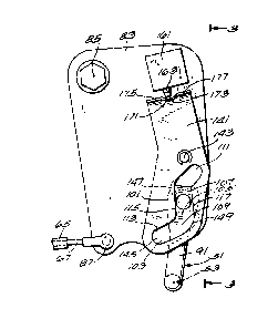
1308995
While other constructions can be
employed, in the illustrated construction, the means
for permitting over-travel of the inner core 67 after
effecting driving engagement of the reversing
transmission 37 includes cam and follower means
connected to the inner core 67 of the push-pull cable
53 and to the shift lever 51.
More particularly, while other
constructions can be employed, the cam and follower
means include a shift member or plate 83 which is
pivotally mounted on the marine propulsion unit about
pivot axis 85 in parallel spaced relation to the
pivot axis 53 of the shift lever 51. In addition,
the shift member or plate 83 is pivotally connected
at a point 87 remote from the axis 85 to the inner
core 67 of the push-pull cable 63 so that lengthwise
movement of the inner core 67 effects pivotal
movement of the shift member or plate 83.
The shift lever 51 is configured to
include an arm 91 which extends in spaced parallel
relation to the shift member or plate 83 and in
transverse relation to the shift lever axis 53.
The shift member or plate 83 and the
shift lever arm 91 are provided with a cam slot and
follower mechanism so as to afford movement of the
shift lever 51 to operate the reversing transmission
37 in response to shift member pivotal movement and
to afford over-travel of the shift member of plate 83
--11--
13 [)8~95
relative to the shift lever 51 upon completion of the
shifting action of the reversing transmission 37.
The cam slot and follower mechanism
comprises a follower 101 which extends from one of
the shift lever 51 and the shift member or plate 83
(from the shift lever 51 in the dislcosed
construction) and which is received in an inclined
and closed transmission actuating cam slot 103 which
is provided in the other of the shift plate or member
83 and the shift lever 51 (in the shift plate 83 in
the disclosed construction). The cam slot 103
includes a central or transmission actuating portion
105 with opposite upper and lower ends 107 and 109,
respectively, and upper and lower end, dwell, or
over-travel portions 111 and 113 respectively
extending from the upper and lower ends 107 and 109
of the central or transmission actuating cam slot
portion 105. Still more particularly, the central
portion 105 includes opposite side edges 115 and 117
and has a lengthwise center line 121. In order to
effect shift lever movement in response to shift
member movement, the center line 121 extends at a
radius 123 from the shift plate pivot axis 85, which
radius 123 increases from the upper cam slot end 107
to the lower cam slot end 109. Accordingly, movement
of the shift member or plate 83, when the follower
101 is in the central portion 105 of the cam slot
103, will cause pivotal movement of the shift lever
-12-
131~8995
51 to effect movement of the clutch member between
the neutral and the two drive positions.
The cam slot end portion 111 extends
from the upper end 107 of the central portion 105 and
includes a center line 125 having a constant radius
127 from the pivot axis 85 of the shift member 83.
Thus, pivotal movement of the shift member 83,
occurring after the follower 101 is located at the
upper end 107 of the central portion, serves only to
rotate the shift member 83 past the follower 101 and
does not cause pivotal movement of the shift lever
51. Accordingly, over-travel of the inner core 67 of
the push-pull cable 63 beyond the travel which
effects one drive engagement of the reversing
transmission is permitted.
The other or lower end portion 113
extends from the other or lower end 109 of the
central portion 105 and likewise includes a center
line 131 having a constant radius 133 from the shift
member pivot axis 85. Thus, pivotal movement of the
shift member 83, occurring after the follower 101 is
located at the lower end 109 of the cam slot central
portion 105, serves only to rotate the shift member
83 past the follower 101 and does not cause pivotal
movement of the shift lever 51. Accordingly, as
before, over-travel of the inner core 67 of the
push-pull cable 63 beyond the travel which effects
~3 1)8S9S
the other drive engagement of the reversing
transmission 37 is permitted.
In operation, movement of the cable
inner core 67 to the left in the drawings from the
neutral position shown in Figure 2 serves to rotate
the shift plate or member 83 in the clockwise
direction as shown in Figures 2 and 4 through 7.
Such movement of the shift member or plate 83 engages
the cam slot side edge 117 with the follower 101 and
causes the follower 101 to move to the upper end 107
of the cam slot central portion 105 as shown in
Figure 4. Such follower movement causes
counter-clockwise rotation of the shift lever 51 to
cause the reversing transmission 37 to shift into one
drive engagement. Continued movement of the inner
core 67 to the left causes additional clockwise
movement of the shift plate 83 relative to the
follower 101 but does not effect pivoting movement of
the shift lever 51. Return movement of the inner
core 67 to the right from the drive position shown in
Figure 4 to the neutral position shown in Figure 2
will engage the cam slot side edge 115 with the
follower 101 and cause downward travel of the
follower 101 in the cam slot 103 to the central
neutral position, thereby causing return of the shift
lever 51 in the clockwise direction to the neutral
position shown in Figure 2, and thereby returning the
reversing transmission 37 to neutral.
-14-
131~)8995
Movement of the cable inner core 67 to
the right in the drawings from the neutral position
shown in Figure 2 serves to rotate the shift plate or
member 83 in the counter-clockwise direction as shown
in Figures 2 and 4 through 7. Such movement of the
shift plate 83 engages the cam slot side edge 115
with the follower 101 and causes the follower 101 to
move downwardly to the lower end 109 of the cam slot
central portion 105 as shown in Figure 5. Such
follower movement causes clockwise rotation of the
shift lever 51 to cause the reversing transmission 37
to shift into the other drive engagement. Continued
movement of the inner core 67 to the right causes
further counter-clockwise movement of the shi.ft plate
or member 83 but does not cause pivotal movement of
the shift lever 51.
Return movement of the inner core 67 to
the right from the other drive position shown in
Figure 5 to the neutral position shown in Figure 2
engages the cam slot edge 117 with the follower 101
and causes upward travel of the follower 101 in the
cam slot 103 to the central neutral position causing
return of the shift lever 51 in the counter-clockwise
direction to the neutral position shown in Figure 2
and thereby returns the reversing transmission 37 to
neutral.
Various means or arrangements can be
provided for temporarily interrupting engine ignition
131~)8995
at the time of clutch disengagement. In the
disclosed construction, such means comprises a switch
plate or member 141 which is mounted on the shift
plate or member 83 for relative movement there
between. In particular, in the disclosed
construction, the switch plate or member 141 is
mounted on the shift plate or member 83 for pivotal
movement about a pivot axis 85.
Included in the switch plate 141 (See
Figure 6) is a closed shift interrupting cam slot 145
which, except as noted hereinafter, is generally
identical to the cam slot 103 in the shift member or
plate 83 and which also receives the follower 101.
Accordingly, the same numbers used in connection with
the cam slot 103 will be used with respect to the cam
slot 145. The cam slot 145 in the switch member or
plate 141 differs from the cam slot 103 in the shift
member or plate 83 by reason of the provision,
adjacent the juncture of the central portion 105 and
the upper end portion 111, in the cam slot side edge
115, of a recess 147, and the provision, adjacent the
junction of the central portion 105 and the lower end
portion 113, and in the other cam slot side edge 117,
of a second recess 149.
The means for temporarily interrupting
engine ignition also includes switch means connected
to an ignition system (not shown) and operable, when
actuated, to interrupt or prevent engine ignition.
-16-
13~)8~95
Such switch means can take any suitable form and can
be operable either upon opening of the ignition
circuit or upon closing of the ignition circuit to
ground, depending upon the type of ignition circuit
employed. In either case, actuation of the switch
means, either by opening or closing, serves to
interrupt ignition.
While other constructions can be
employed, in the disclosed construction, the switch
means includes a suitable electrical switch 161 which
is connected to the ignition circuit and which
includes a plunger 163 which is movable between
extended and retracted positions, and which, when
depressed into the retracted position, actuates the
switch 161. The switch 161 can be mounted on either
of the shift plate 83 or the switch plate 141 and, in
the disclosed construction, is mounted on the shift
plate 83.
The switch means also includes a switch
actuator 171 which can be formed on either the shift
plate 83 or the switch plate 141 and which, in the
disclosed construction, is formed on the switch plate
141. The switch actuator 171 comprises a foot or
flange which projects from the switch plate and which
provides a profile or surface having a recess 173
which is located between two shoulders 175 and 177
and which receives the plunger 163 in extended
condition when the switch plate cam slot 145 is
-17-
13~8995
aligned with the shift plate cam slot 103. However,
when the switch plate 141 moves (pivots) relative to
the shift plate 83, one of the shoulders 175 and 177
serves to depress the plunger 163 to actuate the
switch 161 to cause temporary ignition interruption.
In operation, when the shift plate 83
and the switch plate 141 are in alignment, as shown
in Figures 2, 4, and 5, and when the inner core 67 is
displaced to the right to disengage the reversing
transmission from the one drive engagement, initial
movement of the shift plate 83 in the
counter-clockwise direction will cause the follower
101 (See Figure 6) to pivot the shift lever 51 toward
neutral and will also permit entry of the follower
101 into the recess 147, thereby effecting relative
pivotal movement between the shift plate 83 and the
switch plate 141 and thereby causing the shoulder 175
to depress the plunger 163 to actuate the switch to
161 cause ignition interruption. Continued movement
of the shift plate 83 in the counter-clockwise
direction causes continued movement of the follower
101 downwardly in the central slot portion 105 from
the upper end 107 and toward the neutral position.
During such movement, the follower 101 rides out of
the recess 197 and into the central portion 105 of
the switch plate ignition interrupting cam slot 145,
causing re-alignment of the cam slots 145 and 103 in
the switch plate 141 and in the shift plate 83,
-18-
131[)8~95
respectively. Such reverse relative movement between
the shift plate 83 and the switch plate 141 returns
the recess 173 into alignment with the switch plunger
163 and affords extension of the plunger 163 to the
extended position, i.e., de-activates the switch 161
so as to permit normal operation of the engine
ignition system.
When shifting out of the other drive
engagement, and from the position of the components
shown in Figure 5, initial movement of the shift
plate 83 in the clockwise direction will cause the
follower 101 to displace the shift lever 51 toward
neutral and will also permit entry of the follower
101 into the recess 149, thereby effecting relative
pivotal movement between the shift plate 83 and the
switch plate 141 and thereby causing the shoulder 177
to depress the plunger 163 to actuate the switch 161
to cause ignition interruption. Continued movement
of the shift plate 83 in the clockwise direction
causes continued movement of the follower 101
upwardly in the central slot portion 105 from the
lower end 109 and toward the neutral position.
During such movement, the follower 101 rides out of
the recess 149 and into the central portion 105 of
the switch plate cam slot 145, causing re-alignment
of the cam slots 103 and 145 in the shift plate 83
and in the switch plate 141, respectively. Such
reverse relative movement between the shift plate 83
--19--
13 [)8~95
and the switch plate 141 returns the recess 173 into
alignment with the switch plunger 163 and
de-activates the switch 161 so as to permit normal
ignition operation.
If desired, the shift lever or member
83 can be provided with a spring mass damper (not
shown) to reduce transmission of chattering to the
remotely located control lever 71, which chattering
can occur in response to clutch member movement.
The over-travel feature disclosed
herein beneficially serves to reduce the forces
applied to the push-pull cable which actuate the
reversing transmission and thereby lessens wear and
increases the serviceable life of such actuating
cable.
The ignition interruption feature
serves to beneficially reduce the loading on the
components of the reversing transmission during
disengagement thereof and to reduce the effort
required to disengage the reversing transmission.
Various of the features of the
invention are set forth in the following claims:
-20-