Note : Les descriptions sont présentées dans la langue officielle dans laquelle elles ont été soumises.
1 3 ~
A SUBMERGED NOZZLE FOR STEEL CASTING
BACKGROUND OF THE INVENTION
This invention relates to a submerged nozzle for guiding
molten steel from a tundish to a mold in a continuous steel
.... ,. _ " ,
casting apparatus.
In a conventional steel casting apparatus which uses a
submerged nozzle, argon gas is blown into molten steel which is
moving down through the submerged nozzle in order to avoid the
adherence of steel debris onto an inner sur~ace of the nozzle
and the generation of blocking thereof.
The argon gas moves along the molten steel flow in and out
of the submerged nozzle and then floats to the surface of a
molten steel in a mold where a mold powder layer exists. On
this occasion, the gas moves from the molten steel having a
larger specific weight to the mold powder layer having a smaller
specific weight. At the boundary surface, the volume of the
argon gas suddenly expands and bursts.
The gas bursting accompanied by the drastic change in volume
of the gas agitates the mold powder layer so that the molten
steel damages a nozzle powder line section of the nozzle.
13~3g
The damage of the noæzle is marked especially when argon gas
bubbles move up to the surface of the molten steel near the
powder line section of the submerged nozzle.
~ y taking into consideration the foregoing, an attempt was
made to improve a submerged nozzle by increasing a thickness of
the powder line section of the nozzle so as to prolong the
service life of the powder line section as compared with a prior
art submerged nozzle which has a straight type of powder line
section. However, the speed of damage, which can be expressed as
a thickness of a damaged portion per unit time, does not
substantially change.
In addition, in case of the straight powder line section
type submerged nozzle, the gas bubbles move up directly from the
discharge port and floats near the nozzle, which makes it
possible to attain only the advantageous effect which can be
afforded by the increase in thickness and nothing more.
Japanese Utility Model Laid-Gpen No. 59-89648 discloses a
prior art submerged nozzle provided with a projecting part
having a slanting surface of a negative angle at an upper end
portion of a discharge port. The submerged nozzle is provided
between a tundish or ladle (not shown) and a mold 90 ~ lower
end portioQ of the submerged nozzle 1 is immerged in a molten
1 3 `~
steel 10 in the mold 9. A nozzle passage la is formed in the
nozzle 1 and connected with two or more discharge ports 2 so as
to guide a molten steel into the mold 9 in the direction
designated by the arrows. A projecting part 4' is Eormed at an
upper end of each discharge port 2 for guiding both the molten
steel 5 and the argon gas bubbles 3. The projecting part 4' has
a slanting surface having a negative angle to a horizontal line
so that the slanting surface is inclined downwardly. The
slanting surface of the projecting part 4' and a slanting
surface of the discharge ports constitute a common sur~ace which
is inclined downwardly in a negative direction.
However, it is merely effective to keep the floating
position of the gas bubbles far from the powder line section.
The gas bubbles ejected from the discharge pGrt collide directly
against the slanting surface of the projecting part. Resultant
from this, the damage of the projecting part becomes a more
serious problem. Therefore, it cannot be avoided to reduce the
life time of the projecting part.
In a steel casting apparatus which uses a submerged nozzle,
recently, the demand for multiple continuous casting and
multiple duration service has been accelerated in order to
obtain operating advantages and reduce production costv
~ 3 ~
In general, as the powder line section is subject to the
most critical problem in terms of service life, a ZrO2-C
material having an e~cellent anti-corrosion is used for the
powder line section of the submerged nozzle.
In case of the submerged nozzle having a straight powder
line section, the powder line section must be ~urther improved
since it is subject to greater damages in comparison with the
other nozzle sections.
In case of a submerged nozzle having a projecting part with
a slanting surface at an upper end of a discharge port, the
projecting part faces the gas bubble flow substan-tially at a
right angle, which produces unavoidable phenomena such as
damages by the molten steel at the projecting part. In
addition, the flow of air bubbles are changed into turbulent
flow after the collision of the gas bubble flow against the
projecting part of the nozzle and the increase of the agitation
effects.
SUMMARY OF THE INVENTION
The object o~ this invention is to provide a submerged
nozzle for use in steel casting in which damage by molten steel
can be reduced so as to prolong service time and gas bubbles can
~3~3~
be easily controlled so as to float at a position or positions
sufficienty distant from a powder line section of the nozzle.
According to this invention, a submerged nozzle for use in
steel casting comprises a nozzle body, a nozzle passage formed
through the nozzle body so as to extend from an upper end of the
nozzle body to a lower portion of the nozzle body in its
longitudinal direction, a plurality of discharge ports formed i~
the lower portion oE the nozzle body so as to face outwardly,
the discharge ports being connected to the nozzle passage, and
a projecting part pro~ided around the nozzle body at an upper
end of the discharge ports and having a slanting surface which
is located from the upper end of the discharge ports and
inclined upwardly in a positive direction.
Preferably, the projecting part has a thickness (A) ranging
from 5 mm to 50 mm, the thickness being a size from an outer
surface of the nozzle body up to an outer top of the projecting
part, a height ~B~ ranging from 10 mm to 200 mm, the height
being a size from the upper end of the discharge ports to the
upper end of the outer top of the projecting part, and a
slanting angle (C) ranging from 5 degrees to 60 degrees, the
slanting angle being an angle between an imaginary horizontal
plane and the slanting surface. A prefered example of the
slanting surface is a taper-shaped surface. The projecting part
may be integral with or separate from the nozzle body.
~3~9~3~
The discharge ports each has a slanting surface which is
inclined downwardly in a negative direction and connected to a
lower end of the slanting surface of the projecting part. An
angle formed between the slanting surface of the discharge ports
and the slanting surface of the projecting part is a~out 90
degrees.
BRIFF DESCRIPTIO~I OF THE DRAWINGS
-
By way of example and to make the description more clearr
reference is made to the accompanying drawings in which:
FIG. 1 is a sectional view showing a pro~ecting part of a
submerged nozzle and its related portions according to this
invention,
FIG. 2 is a cross sectional view showing a submeged nozzle
and its related members according to this invention,
FIG. 3 is a cross sectional view showing a projecting part
of a submeged nozzle and its related portions according to this
invention, and
FIG. 4 is a cross sectional view showing a prior art
submerged nozzle and its related members.
~3~3~
DESCRIPTION OF EMBODIMENTS
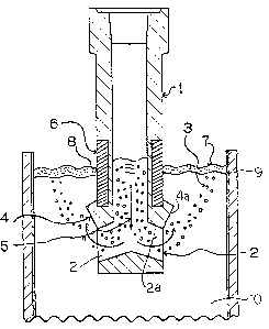
A submerged nozzle for use in a continuous steel casting
apparatus is provided between a tundish or ladle (not shown) and
a mold 9. A lower end portion of the su~merged nozzle 1 is
immerged in a molten steel 10 in the mold 9. A nozzle passage
la is formed in the nozzle 1 and connected with two or more
discharge ports 2 so as to guide a molten steel into the mold 9
in the direction designated by the arrows in Fig. 2.
A projecting part 4 is formed around the nozzle 1 at an
upper end o~ each discharge por-t 2 for guiding smoothly both the
molten steel 5 and the argon gas bubbles 3. The projecting part
4 has a taper-shaped slanting surface 4a having a positive angle
to a horizontal line so that the slanting surface is inclined
upwardly. The gas bubbles 3 move up along the slanting surface
4a in the direction of the arrows from the discharge ports 2.
The projecting part 4 functions to adjust the directions of
the gas bubble flow 3 and the molten steeel flow 5. The argon
gas bubbles 3 float along the molten steel flow 5 at a position
or positions far from the powder line section ~ of the submerged
noz~le 1. Therefore, it becomes possible to reduce the agitation
effects accompained by the volume expansion and bursting during
the float of the gas bubbles 3 at the powder layer 7 and avoid
"
~3~3~
the damage of a portion 8 of the powder line section 6 which
contacts the powder layer 7.
A desired shape of the projecting part 4 will be explained
as follows:
In order that the argon gas is capable of floating at a
sufficiently distant position from the nozzle powder line
section 6, the projecting part 4 has a thickness A ranging
between 5 and 50 mm, a height B ranging between 10 and 200 mm
and a slanting angle C ranging b~tween 5 and 60 degrees. As
illustrated in Fig. 1, the thickness A is a size from the outer
surface of the nozzle 1 to the top of the projecting part ~, and
the height B is a size from the upper end of the discharge port
2 to the top of the projecting part 4, and the slanting angle C
is an angle from an imaginary horizontal line to the slanting
surface 4a in the unti-clockwise directionO
According to this invention, the generation of foaming and
bursting pheno~ena can be effectively avoided so that the gas
bubbles can float on the surface of the molten steel 10 in the
mold g smoothly.
Furthermore, according to this invention, the gas bubbles 3
bound at the projecting part 4 so as to scatter, thereby
avoiding generating a turbulent flow, in particular when
13~8~
compared with the projecting part 4' of the prior art submerged
nozzle shown in Fig. 4 in which the slanting surface of the
projecting part 4' has a negative angle to an imaginary
horizontal line.
In addition, the present invention makes it possible to
reduce the damage of the projecting part 4 and hence prolong the
service life of the submerged nozzle 1 since the gas bubbles 3
move along the slanting surface 4a of the proiecting part 4. On
the contrary, the prior art projecting part 4' illustrated in
Fig.4 is directly subject to the pressures of the gas bubbles 3
and the molten steel flow 5.
Preferably, each of the discharge ports 2 has a slanting
surface 2a which is inclined downwardly in a negative direction
and connected to a lower end of the slanting surface 4a of the
projecting part 4. An angle formed between the slanting surface
2a of the discharge ports 2 and the slanting surface 4a of the
projecting part 4 is about 90 degrees.
Although in the embodiment of Figs. 1 and 2 the projecting
part 4 is integral with the body of the nozzle 1, a ring-shaped
projecting part 4 which is separate from the nozzle body can be
attached to a straight type nozzle at an upper end of the
discharge ports 2 as sho~n in Fig. 3. In order that the argon
gas is capable of floating at a sufficiently distant position
.. .. . .
i
from the nozzle powder line section 6, the projecting part 4 has
a thickness A ranging between 5 and S0 mm, a height B ranging
between 10 and 200 mm and a slanting angle C ranging between 5-
and 60 degrees. As illustrated in Fig. 3, the thickness A is a
size from the outer surface of the nozzle 1 to the top surface
of the projecting part 4, and the height ~ is a size from the
upper end of the discharge port 2 to the upper end of the top
surface of the projecting part 4, and the slanting angle C is an
angle from an imaginary horizontal line to the slanting surface
in the unti-clockwise direction.
In the embodiment shown in Fig. 3, as a ring-shaped
projecting part 4 can be replaced by another one, it is easy to
change the slanting angle C, the height B and the thickness A in
such a way that the functions of the projecting part can meet
the service requirements. Although not shown, ~he ring-shaped
projecting part can be fixed to the nozzle body by means of
screws, mortar, pins or the like.
According to this invention, it becomes possible to prolong
the service life sharply without increasing a wall thickness of
the powder line section of the submerged nozzle.
Generally, the damage by the molten steel is produced by:
(1) the diffusion of low melting point-based compound within the
~ 3 ~
steel caused by chem~cal reaction against the alkali compounds
(CaO, MgO, Na20, K~O, CaFa);and
(2) the desorption of ZrO2 particles resulting from the
oxidation consumption of resin coke and graphite of the
materials (ZrO2-C) of the powder line section in the nozzle 1.
The factors which are responsible for controlling and
amplifying the speed of damage by the molten steel at -the powder
line section mainly comprise:
(a) the agitation of molten steel within the mold
(electromagnetic agitation and mold oscillation); and
(b) the agitation force (air vibration) produced by the
expansion when the argon gas to be injected in the molten steel
floats on the surface of the molten steel within the mold.
This invention can control the direction of the molten steel
flow, keep away the floating, expansion and foaming positions of
the argon gas from the powder line section of the submerged
nozzle and hence reduce the in~luence of the agitation force
accompanied by the floating and expansion of argon gas as
defined in the above-stated item (b).
;.
~ 3 ~
A submerged nozzle having a projecting part according to
this invention can provide a service life several ~imes longer
than the prior art noz~les since it is capable of discharging
argon gas into the mold smoothly and allowing the gas to float
at a distant position Erom the mold powder section of the nozzle
and preventing the gas from turning into a turbulent flow.