Note : Les descriptions sont présentées dans la langue officielle dans laquelle elles ont été soumises.
1 31 1 63~
DEVICE FOR REPRODUCING STATIC OR MOVING THREE-DIMENSIONAL
IMAGES, THAT IS FOUR-DIMENSIONAL, WITHOUT THE USE OF
COHERENT LIGHT
Background of the Invention
This invention refers to reproducing three-
-dimensional static or moving images and constitutes an im-
provement on the object of the Spanish Patent with publica-
tion number 2000293 (application number 8603612, filed 29December 1986).
In this patent an installation is claimed for
obtaining moving three-dimensional, that is four-dimensional,
images whether in colour or in black and white, characteriz-
ed in that it comprises some stereoscopic photographing meanswith various optical objectives, pertaining to a single or
different cameras, whose optical centres are to be found in
a horizontal plane; and by some reproduction means comprising
as many projection objectives, pertaining to a single or dif-
ferent projectors, as objectives that are used in the takearranged in such a way that they project their images onto a
screen made of transparent optical material comprised by an
optical line of vertical cylinders, allowing observation by
tra~sparency of the vertical component of the image.
However, difficulties have been found in put-
ting the obJect of that patent into practlce, difficulties
which have made additional studies necessary, which have led
to development of the invention claimed in the present appli
cation.
Before defining the present invention it is
considered convenient to study the prior art knowledge where
of has been~acquired and, in tXis way, demonstrate the great
advantages of the present invention.
Appreciation of the distance that lies between
an~ob8erver and the ob~ec~ts observed is achieved by the brain
ynthe8izing two images taken from two different points, o~e
:, . :
: . : ~ .
from the right eye and the other from the left.
The systems of taking and reproducing images
with depth, developed up to now, can be divided into two
major groups. The most modern ones, after 19~7, based on
the formation of images due to the interference of beams of
coherent light, holographic systems, and those which are not
recorded through wave interference, non-holographic systems.
Amongst the latter the stereoscopic and three-
dimensional system differ from one another. The term stereo-
scopic (stereogram) is used for systems in which two imagestaken at a distance approximately equal to the average dis-
tance between the human eyes are used in the reproduction.
The term three-dimensional (Panoramagram) is used when the
system uses a greater number of taken and reproduced images,
allowing observation within a wide viewing angle, ~ithout
inconveniencing the observers by placing before them optical
filters or any other contrivance.
The field of application of this invention is
then that of three-dimensional reproduction, as has just been
defined, in motion.
Below we will examine the various systems used
for taking and reproducing images with depth.
The technique of holography is based on photo-
graphy by reconstruction of wavefronts. These systems require
coherence of the light sources of both image taking and image
reproduction. The temporal coherence requires the light to
be monochromatic. The spatial coherence requires the light
to come from apoint source.
Both the objects which are going to be photo-
graphed and the images which have to be reproduced need to be
illuminated with coherent light only (dark room), therefore
the develop~ènt of these systems has been intimately linked
with the development~of the laser, since its light ie intense
and highly coherent.
The laser technique is complex and expensive
a~d holograms produced in this way require great technical -
: .
., ~ . " .. ... .
: '
13l 1633
--3--
difficulties to be overcome.
This has hindered the commercialization of sys-
tems, using this process, capable of achieving photographs of
distant objects which, like the moon, cannot be lit up with
a coherent bea~. It turns out to be impossible to photograph
sunsets of reflections of the sun or moon on the sea, land-
scapes, etc. Finally, as observation through transparency
is necessary, the size of the reproduced image is limited.
Among the non-holographic systems are the
stereoscopic systems, which are suitable for projection,
based on bringlng a different image to each eye. The photo-
graph is taken with two cameras, the objectives of which are
separated from one another by a distance approximately equal
to the average value of the distance betw~en the human eyes.
The systems of reproduction are very varied,
depending on the procedure used to bring the image taken by
the lefthand camera to the left eye and that taken by the
righthand camera to the right eye. They all require the
observer to be provided with an optical, electronic or elec-
tromechanical appliance in front of his eyes.
Without attempting to be exhaustive, we wi]l
mentlon some of the most well known methods used in stereo-
scoplc proiections with motion, such as those which use
coloured, polarized or shuttering filters.
The systems with coloured filters (anaglyphs)
are able to bring a different image to each eye by placing a
filter in front of each of the observer's eyes, red (or
yello~) for one eye, green (or bl~e) for the other, each
image being reproduced well in red (or yellow) or in green
~30 (or blue), as it corresponds to one or other of the eyes.
In systems witX polarized light~ polarized
f~ilters~a~re placed before the observer. The planes of
pola~rization of the filters of the eyes are perpendicular
to one another.~ The planes of polarization of ~he light
35~ wh~ich reproduces the ima~ges ~are the same as those of the
:: :.; : , : , : - .. :.
4 131 1633
observer's filters.
In the shuttering systems, a system is placed
before the observer which can interrupt the vision of each
eye by shuttering Each eye has a viewing time which coin-
cides with the shuttering of the other. The images are alsoreproduced alternately and with the same frequency.
The principal limitation of the stereoscopic
systems used in projection is that they require the observer
to be inconvenienced by placing before him coloured or polar-
10 ized filters or a shuttering mechanism.
Other stereoscopic systems also exist in whichbringing a different image to each eye is achieved by means
of procedures which are not suitable for projection. Amongst
these are those which place an optical systems between the
observers and the reproduced image, such as the Brewster
prism method, (lB), the Wheatstone flat mirror method (lB)
or Kemp's concave mirror method, U.S. Patent 4.623.223.
However, these systems do not belong to the
field of three-dimensional reproduction.
Amongst the three-dimensional systems of re-
production using ordinary llght developed up to the present,
there are some which are capable of reproducing images in
three dimensions and in motion, allowing the observer to
~; move from left to right or viceversa, the reproduced image
sho~wing its right or left hand side respectively. In the
first place there are the systems for reproduction of the
~ horizontal parallax. The factors to consider in a comparison
-~ ~ of~ the various systems are~
The~orthoscopic viewing angle, the quality of
the reproduced image and the cost resulting from the com-
plex~ity o f ~manufacture.
35~ 1;B) Norling, J.A., The stereoscoplc Art. ... A Reprlnt.
J . ~Sm p t: 6 0, nQ 3, 286-;308~(March 1953)
,
~. : - ~ : . :
: : ~ . - ~ , ::,
131 1~33
All the devices for three-di~ensional repro-
duction developed up till now use a "diffusion surface" on
which the various images are generated, projected, transmit-
ted, amplified or, simply, printed. Typical of generation
is the cathode ray tube screen, for projection onto opaque
or translucent surfaces, used by commercial cinematography
or television projection and transmission, which use
light conductors or amplifiers.
It is important to emphasize one essential
characteristic common to any diffusion surface, which great
ly affects the design of all devices for three-dimensional
reproduction which use this type of surface.
This essential characteristic is that: "Any
point of the diffusion surface is transformed into a centre
transmitting light photons in all directions".
As a consequence, any observer, whatever his
position, will see the whole image reproduced o~ the dif-
fusion surface.
If two or more images are reproduced at the
; 20 same time, at the same point of the diffusion surface, the
; photons coming from the different images appear mixed to
gether, whatever their direction.
For this reason, distinguishing the differ-
~` ent images reproduced on the diffusion surface is achieved
by reserving a different place for each of them, that is, bymeans of "scalar image differentiation".
All the systems designed up till now manage
to reserve a different position on the diffusion surface for
each image using a different procedure. This position is
uæually a very fine vertical stripe.
In Morishita's U.S. Patent n 4,737,840, the
~procedure used i6 that of projection through a vertically
` striped shield plate, placed in front of the diffusion sur-
-~ ~ face. Each projection al~ays appears on the diffusion sur-
face in a different place, in a different vertical stripe.
The procedures to achieve tbis objective mentioned by
:
:~ ~ ' : : . ' ' ': .
,
~ , - " :''~ `
~3~ 1633
Morishita are bo~h complex and expense.
In Haisma's U.S. Patent n 4,571,616 also, each
image appears within a different vertical stripe. In this
case the images are positioned after being guided along light
conductors.
In both cases, as in all the systems in use
designed up till now, the view is made through an optical
sheet of cylindrical lenses, (lenticular sheet), the focal
lines of which are contained on a plane at which the dif-
fusion surface is situated.
It is important to bear in mind that the transverse dimensions of each vertical image stripe must be n
times smaller than the size of the cylinder, n being the
number of images to be reproduced. For this reason the size
of the cylinder is limited by that of the image, which is in
turn n times smaller than that of the said cylinder.
The quality of the image is limited by the
transverse dimensions of the cylindrical lens which is in
turn limited by that of the width of the vertical stripe of
', 20 the image.
The maximum viewing angle is limited by the
aperture of the cylinder, the relationship between the trans-
verse dimensions of this and lts focal length; if this angle
is exceeded, observation is made on an image stripe corre-
sponding to the attached cylinder, producing an undesirablepseudoscopic effect, that is, inverted depth.
In these systems the optical sheet of verti-
cal cylinders is at its focal length from the diffusion sur-
face, a focal length of around a millimeter, and it is the
diffusing screen itself which makes the simple development
of front projec`tion systems impossible.
Below we will give a critical examination of
t:he three-dimensional systems developed up till now, which
we have described above.
1:
In aIl the systems for reproducing the hori-
.zontal parallax of three-dimensional images which we have
:
, .... .. . . .
:
:: :
,
131 16;~3
just discussed, the following are used:
A- The optical sheet of vertical cylinders, at the focal
plane of which i8 placed a diffusion surface.
B- Dlffusion surface on which the images appear divided
into fine stripes.
The same number of image stripes as are used
are made to correspond to each cylinder.
To ensure a good quality reproduced image it
will be necessary:
1.- That no space appear between each two adjacent
cylinders. The cylinders must be in contact with
one another.
2.- That the size of the cylinders be small enough to be
imperceptible.
3.- That the variation of the hori~ontal parallax appear
to be continuous, within a viewing angle wide enough
so that pseudoscopy does not occur for any observer.
The 1st condition requires the transverse
dimensions of the image, group of n stripes, corresponding
to each cylinder, to be at the most the transverse dimen-
sions of the latter.
According to this condition, the maximum
viewing angle without pseudoscopy is expressed by
~j lcylinder transverse dimensions~
2 tag 1 ~ 2 x focal length /, which for ordinary
-materials, the refractive indices of which vary around 1,5,
takes a value of approximately 54Q; clearly insufficient in
the ma~ority of cases, since it implies + 27Q around the
perpendicular at the diffusion surface.
The preservation of this angle across the
~hole screen~requires a precise-correspondence between each
cylinder and its image (group of n stripes). This corre-
pondence is difficul~ to achieve and therefore expensive
` to manufacture. ~
3~5 ~ ~ The 2nd condition requires the si~e of the
.cyllnders to~be~ small enough to~be imperceptible.
131 1633
The condition of not being perceptible for
a stripe of transverse dimensions "d" for a healthy eye is
that
d ~ viewing distance in meters
.. ..
3,500
For example: 0,3 mm. for a distance of 1 m. and
0,8 mm. for a distance of 0,25 mm.
If lO images are used, the transverse dimen-
sions of each image stripe have to be 0.03 and 0.008 mm.,
respectively. These values are of the order of only 15 times
greater than the wavelength of visible light. If a number
of images greater than 10 were used, the situation would,
logically, become worse. The difficulties in manufacture are
obvious and, therefore, the price of the commercial product
~ would be hlgh.
; The 3rd conditlon requires the orthoscopic
viewing angle to be greater than 54Q and a continuous transi-
tion from one image to the next, when the observer moves from
right to left or viceversa. Both restrictions resulting from
this 3rd condition are incompatible with the 1st and 2nd con-
ditions dicussed above.
The first would require an image through a
cylinder of greater size than this, which would lead to a
; loss of image quallty. The second wou]d requlre the use of
8uch fine image stripes that their manufacture would not be
viable.
hese reasons explain why these systems have
not been brought onto the market successfully, not even in
cl~ematography with small projection screens.
In the second place within this general tech-
n~olog~y, are the integral reproductlon syst~ems. This is~what
s~ystems ~capable of reproducing the horizontal and~vertical
35~ pa~rallax~ simultaneously are called.
131 16~3
_9_
We owe this invention to Lippmann, the famous
French optics scientist, in 1908 (2B).
At present the basis of integral photography
is to prepare a fly's eye lens sheet, out of glass or plas-
tic, with a tremendous number of spherical plano-convex
lenses (for exa~ple 10,000).
An example of integral reproduction is Ando's
patent number 3,852,524.
Ando does not at any time mention the number
of images taken nor the width of the band required for their
transmission. He says simply that they are multiple and are
a carrier of very high frequency.
In fact, this process of image taking and re-
production requires the handling of an enormous amount of
information, because behind every plano-convex lens a full
two-dimenslonal image is taken in.
To make the system work, the number of plano-
-convex lenses used, both for image taking and for reproduc-
tion, must be in the order of thousands.
Apart from these problems, and that of using
spherical optical screens, reproduction is always carried out
in all the forms described in his patent through a diffusion
surface with all the drawbacks which the use of this entails.
Haisma describes, in his Patent nY 4,571,616,
already mentioned, an integral relief system based on taking
the image with conventional cameras forming a square mosaic.
; He g1ves as an example the number of 9 cameras arranged in 3
columns of 3 cameras each.
Reproduction continues to be done by position-
30~ ing nine different sections of images behind each spherlcal
lens, one section for each image taken. He says that adjust-
ment is achleved by appropriately positioning the optical
2B) Lippmann, ~.G., Epreuves Reversibles Donnant la
35~Sensation du Relief. .J. Phys. 7, 4th Series, 821-825
(Nov-1908)
~ : :
131 1633
--10--
conductors by mechanical means. If we have earlier seen
the complexity of manufacture brought about by the position-
ing of n stripes of image behind each cylinder, the problem
here is much more serious~ since it involves positioning n2
squares of images behind each spherical microlens.
In addition, in the system described by
fIaisma a diffusion screen is used, in this case the ends of
optical conductors.
The drawbacks in the system for reproducing
the horizontal parallax stated above appear here as well,
not only in the reproduction of the horizontal parallax but
also in the reproduction of the vertical parallax and this
has prevented the successful commercialisation of this sys-
tem.
Some other fields of application do also exist
as in robotics, where also, as with Ando, optical screens of
spherical lenses (fly's eye lens sheets) are used, see for
example Stauffer's U.S. Patent n 4,410,~04. ~is purpose
however is that of obtaining data on the range of objects
;; 20 and their shape, never the three-dimensional reproduction of
images with vertical and horizontal parallaxes.
~ .
~ S~MMARY OF THE INVENTION
. :
To remove the drawbacks mentioned a system
has been developed which, as a distinctive feature, does not
use a diffusion surface on which the different images are
focused. There is an ideal plane, on which the images are
focussed, but this plane is not materialised.
~30 For reasons of instruction this plane can be
imagined as a transparent surface.
To follow the same order of explanation as
that used in the exa~ination of the previous procedures, we
will begin by defining the fundamental characteristic of any
transparent surface:
~: :
"Any point of the transparent surface is
:
''::
:
-1 1- 1 3 ~ ~ 6 ~ 3 .
trans~ormed into a centre which emits photons, which retain
the same direction as the incident photon".
Consequently:
- Any observer, whatever his position, will
see a single point of the projected image. This point is
the intersection with the transparent surface of the line
which joins the optical centre of the projector with the
optical centre of the observer.
- If two or more images are projected at the
same time from different spatial positions onto the trans-
parent surface, the photons coming from the different pro-
~ections retain their direction after crossing it. The dif-
ferent images can be distinguished because the photons of
each one emerge from this transparent surface at a different
angle: that is "Angular image differentiation" can be used.
To describe the invention which is the subject
of this report briefly, an optical sheet of vertical cylin-
ders is placed before this transparent surface and at a dis-
;~ tance equal to the focal len~th of these cylindrical lenses.
The choice of focal length of these cylin-
drical lenses is made in such a way that the relationship
between the transverse dimensions of the cylinder and its
focal length is at least equal to the relationship between
projectors and the projection distance and never greater
25 than twice this amount. t
After positioning the vertical cylinders, with
the above characteristics, any observer in any position will
go on to see as many segments of images as projectors. These
segments will line up in a single rectilinear segment. This
~30 rectilinear segment wilI be different for each point of ob-
servation flnd will be contained in the line result~ng from
the intersection of the plane which contains the; projectors
~ and the obs~erver ~ith the transparent projection surface.
;~ ~ A second optical sheet of horizontal cyIin-
35 ders,~the f~ocal lines of ~hich are on the same~focal plane
.as the vertical c~linders and? therefore, coincident with -
~31 1633
-12-
transparent screen devised for purposes of instruction, will
be responsible for converting the above segment into a
rectangle, the base of which is the same size as this same
segment and the height of which is that of the transparent
surface.
The focal length of these hori~ontal cylin-
ders has to be as small as possible contrasted with their
width (semicircular cylinders), in order that their aperture
allows the view, from any point, of a rectangle as tall as
the optical system itself.
The advantages of this system as opposed to
all the other systems in general and contrasted in particular
with that of Morishita and that of Haisma are:
A) The viewing angle can be made as big as may be desired,
it depending only on the number of projectors, the dis-
tance between them and the projection distance.
B) The size or transverse dimensions of the cylinders are
not limited by the number of images and can be designed
to be as small as may be desired, so the quality of the
image is only limited by the manufacturing conditions
of these cylinders.
C) No pseudoscopy is produced when the observer leaves the
field of vision.
D) It is not necessary to create any complex device for
dividing the projected images into ordered and inter-
looking vertical stripes, so the system becomes cheaper
and is very simple to implement.
It is worth pointing out as a drawback that
this system is valid only for projection and cannot be used
~30 in photographic reproductions on paper. On the other hand,
it is possible, with this system, to design three-dimensional
slide viewers.
E) As there is no diffusion surface between pro~ectors and
optlcal system, the two transparent optical sheet above
can be cut on the same specular surface, resulting in
~ ~ ~ ; an optical sheet of as many rectangular mirrors as
`!: : :
~i! :
.
, , .
, .
-13- 1 3116~3
results from the product of the number of vertical
cylinders by the number of horizontal cylinders.
In this case projection would be from the front.
The application of the above technique for
5 obtaining an integral reproduction system is described below.
The same bases which have served to create a
three-dimensional reproduction system, with variation of the
horizontal parallax, can apply to the design of an integral
reproduction system, one which reproduces the variation of
10 the vertical and horizontal parallaxes.
The design of the vertical cylinders was made
for the reproduction of the hori~ontal parallax with the con-
dition that the relationship between the transverse di~en-
sions of the cylinder and the focal length was at least equal
15 to the relationship between the distance bet~een projectors
and the projection distance and not greater that twice this
a~ount.
In order to reproduce the vertical parallax
the projectors are arranged in a rectangle. The design of
20 the horizontal cyllnders will in this case be made with the
same condition as that which obtained for the design of the ?
vertical cylinders. That is, the relationship between the
transverse dimenslons of the horizontal cylinder and its
focal length must be at least equal to the relationship
25 between the distance between vertical projectors and the
projection distance and less than t~ice this amount.
The system which is the sub~ect of thls re-
port, applied to integral reproduction, is clearly distin-
guished from Ando's syste~ in that: it does not use a dif-
30~ fusion surface, with the advantages resulting from this, it
. :
requires much less information, and it uses conventional
optical systems for the cameras taking the images and for
; the p~ro~ect~ors instead of optical sheet of plano-convex
spherical lenses.
35~ ; In contrast with Haisma's integral reproduc-
.tion system, the syfitem which is the sub~ect of this report.,
: ~ .
- 131 1633
- 14 -
applied to integral reproduction, offers the
advantages resulting from not using a diffusion
surface, such as:
- The hori~ontal and vertical viewing angle can
s be as large as may be desired. This angle
depending on the number of projectors, the
distance between them and the projection
distance.
- The horizontal viewing angle is independent of
the vertical viewing angle.
- The transverse dimensions of the vertical and
horizontal cylinders is not limited by the
number of vertical and horizontal images and
can be designed to be as small as may be
desired, so the quality of the image is only
limited by the manufacturing conditions of
these cylinders.
- The pseudoscopic effect does not occur either
in the horizontal or the vertical parallax.
20 - It is not necessary to create any complex
apparatus for dividing the images into ordered
and interlocking rectangles so the system
becomes cheaper and is very simple to put into
practice.
; 2s - There is the possibility of using front
projection.
In accordance with a particular embodiment
of the invention there is provided a system for
~ reproducing images three-dimensionally, the system
; ~ ~: 30 having first projectors spaced from each other a
first distance along a horizontal line, the first
projectors~being for projecting the images, the
images being~from respectively corresponding cameras
spaced along a horizontal~line, this projecting of
3s the images being over a second distance onto an
:: ::
: , ~ ~ , ............ - . - : .
. - :
14 ~ 6 ~3
- a -
optical member from which the images are observed,
the improved optical member comprising:
first optical sheet means comprising
vertical cylindric lenses, the aperture of each
s vertical cylindric lens being at least equal to a
first value of the quotient obtained by dividing the
first distance by the second distance and less than
twice the first value for providing the images with
horizontal parallax; and
second optical sheet means comprising lens
means for vertically expanding the images provided
by the first optical sheet means.
Figures l, 2, 3, 4, 5, 6 and 7 explain the
ideas upon which the new system is based.
Figures 8, 9 and lO describe the system
which is the subject of this report.
Figure l shows horizontal parallax angle E
with which an object P is seen at a distance l from
an observer with a distance b between his eyes.
zo Figure 2 shows in diagrammatic form an
observer 0, looking at an object P through the
window ~B and shows that the bundle of homo-
centric rays Il, corresponding to the left eye
of the observer l~ and the bundle of homocentric
2s rays Dl, corresponding to the right eye
~, ~
.
:
-15-
of the observer l are contained within the homo-
centric beams F1, F2...Fn.
Figure 3 shows in diagramatic form m observers l' 2---m
looking at an object P through the window AB and
demonstrates that the bundle of homocentric rays
I1, I2...Im corresponding to the left eyes of the
rvers l~ 2 ~-m~ and the bundle of homocen-
tric rays D1, D2...~m, corresponding to the right
eyes of the observers l~ 2' m are contalned
within the homocentric beams Fl, F2... Fn.
Figure 4 shows the formation of the image, characteri~ed by
its height Pi, of an object P at a distance D from
a divergent lens S1 of size K and focal length f.
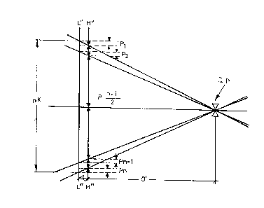
Figure 5 shows the formation of the images, characterised by
their height P1, P2... Pn, contained in the plane
HH' of the object P by the divergent lenses S1,
S2...Sn of size K contained in the plane LL'.
Figure 6 shows the formation of an image IP of an ob~ect,
characterised by its height Pi, at a distance do
of an convergent lens Ci of size K and focal length
f.
Flgure 7 shows the formation of a three-dimensional image IP
; ~ of the objects, characterised by their heights
Pl...Pn, contained in the plane H"H"', at a dis-
tance do from an optlcal sheet of convergent lenses
Cl, C2...Cn contained in the plane L"L"~.
Figure 8 shows n cameras CCl, CC2...CCn separated from one
another a distance~ Kc and with their optlcal axes
parallel.
;3~0 ~Figure 9 shows the arrangemen~ of the projectors PRl,
PR2~...PRn~and of the optical sheet of vertical
cylinders (l) of focal length f and transverse
diMensions d.~ The aistance between two adjacent
pro~iectors is Kr and the pro;ection distance~B.
3~5~ F1gure~10 shows the~optical system which is the ~sub~ect of
this invention. In its front part can be seen the.
: ~ ~ :, , , - ~ . .
:
131 1633
-16- !
optical sheet of vertical cylinders (1), in its
rear part the optical sheet of horizontal cylinders
(2); e is the thlckness of the system, V is the
viewing angle, S is the horizontal angle beneath
which two projectors can be seen, f the focal
length of the vertical cylinders, B the pro~ection
distance, Kr the distance between two ad~acent
projectors and PRl, PR2...PRn the location of the
optical centres of the projectors.
DETAILED DESCRIPTION OF T~E PREFERRED EMBODIM~NTS
GENESIS OF THE INVENTION
Since H. ~inkowski (1907) formulated the
theory of relativity in an abstract four-dimensional space,
three referring to ordinary space and the fourth as a linear
function of time, it has become more and more common to con-
sider our universe as a space-time continuum. The constancy
of length was replaced by the constancy of the interval where
a time function came in to form a part as a fourth dimension.
Following this practice, photographic images
are called here two-dimensional. The invention of the cinema-
tograph meant the addition of a third d~mension, time; so,
the cinematograph is a system capable of handling three-
25~ -dimensional images. In this specification, when we speak
~ ~ ; of four-dimensional images we are referring to moving three-
; ~ -dimensional images.
The passage from the two-dimensional (photo-
graphy) to the three-dimens;ional image (cinematograph) serves
as an~example to explain the new system.
In the first place there was an idea of depar-
~ ture:
J~ "Noving images can be achieved by means of
t~aking a~sequence of static two-dimensional image87~one
35; afte~r~ the~other, which are~then repeated in the same order
,a~nd at t~he~same speed in reproduction. Ff the frequency of.
, , .
t3~ ~633
-17-
images being taken and reproduced is sufficiently high, the
impression of continuity of movement will be perEect".
In the second place, it was necessary to in-
vestigate what the threshold frequency was after which the
human eye could not distinguish the sequence oE discreet
images merging one image with the next in the reproduction,
as though there were a single image continuous in time.
~xperience showed this to be 48 images per second.
In the third place, it was neccesary to in-
vestigate what the threshold frequency was for taking theimages after which the human eye is capable of perceiving
continuity in the movement. This turned out to be 16 images
per second.
Finally~ a procedure was found for producing
moving images which consists of, in synthesis: I. Taking
the images at a rate of 16 images per second. II. Repro-
ducing them at the same rate as above (16 images per second)
interrupting each image twice with a shutter and achieving
a rate of 48 images per second (1 shuttering to change from
one image to the next and 2 shutterings without changing
the image).
At present the standardised procedure in
cinematography is that of 24 images per second with one
additional shuttering per image.
To sum up, the starting point was the basic
idea that: "the third dimenbion, time, is achieved by means
of a sequence of images of two dimensions".
The minimum threshold necesæary so that the
human eye would not perceive the interruptions of light ~as
investigated (48 images per second~. And, finally, a prac-
tical procedure was developed, consisting of taking the
imagee at a rate of 16 images per second and reproducing
the= with additional shu;tterings until a frequency of 4B
times per second of light interruptions was achieved.
~35~ This outline serves as a basis to explain
the genesis~ of the invention as it iæ described below,
. :~
:
~: . ~: , . . :.
::
:: ~
~31 1633
-L8-
according to the model: 1. Exposition of the basic idea. 2.
Experi~entation. 3. Development of the practIcal procedure.
As in the case of cinematography, experience
has shown us that the nu~ber of images to be taken is much
smaller than the number required for reproduction.
Binocular vision is what enables us to ap-
preciate the distance away of objects. This function is
carried out by means of the angle at which the eyes turn.
Let the lines IlAl and DlA2 be the lines of vision to infi-
nity of the left eye Il and right eye Dl respectively. Seefigure 1 which represents an optical diagram of the bin-
ocular observation of an object P.
If the eyes turn to look at an ob~ect P situ-
ated at a distance 1 on the straight line IlAl the right eye
will do it at an angular quantity E given by the equation
b
TgE =
where b is the distance between the eyes of the observer.
The angle E is called the angle of hori-
zontal parallax. As the eyes are normally on a horizontal
line, the systems which reproduce this parallax are suf-
ficient and satisfactory. For this reason the taking and
reproduction of the hori~ontal parallax only form the
essential basis of the folIowing explanation.
Let there be an observer l. . looking at
an ob~ect P through a window AB wide made in a wall perpen-
dicular to the lines of vision to infinity. See fig. 2
which represents the optical diagram of an observer l~
looking at an ob~ect P through the window AB.
This figura 2 shows this observer l~ in plan
view with his right eye Dl, and left eye Il. The bundle of
light rays which, comiDg from the landscape, pass through
~1 (homocentric on Il), i8 the-one which serves to form the
image of the left eye. Similarly, the bundle of light rays
~hich pass through Dl, (homocentric on Dl) serves to form
~ .
,~ :
. ~ ~
~,
.
:: : : '
: ~ , : ,, ~:
-1 9- 1 3 1 1 6 33
the image of the right eye.
The perception of relief is achieved when the
brain synthesises the lmages from the left and right eyes,
formed by these two bundles of light rays, which pass through
the non coincidental points Il and Dl.
The straight line AB, contained in the draw-
ing of the plane containing the window is considered to be
broken up into the series of infinitely close points F
F2 . . .F~ Fn-l ~ Fn-
It is important to note that every ray belong-
ing to the homocentric beam Il, as well as every ray belong-
ing to the homocentric beam Dl, is contained in the group of
homocentric beams Fl, F2...Fn_l, Fn~ so long as the distance
Fl-Fi_l, for whatever i is, is small enough.
If several observers l 2 ' --m
are considered, looking at the same object through the window
AB above and situated at different points, as it is not
necessary to consider the vertical parallax, all the pairs
of eyes can be represented by their projection on a common
horizontal plane. See figure 3 which represents the optical
diagram of m observers observing an object through the window
AB.
It is clear that, for obvious topological
reasons, any homocentric beam Ij or Dj is contained within
the series of homocentric beams Yl, F2...Fi...Fn_l, Fn so
long as the distance Fi-Fi_l is small enough.
In other words, the expression of the basic
idea can be summed up as followfi:
; "The image formed taking as a basis the homo-
30~centric beams I~ or D; corresponding to the left and right
eyes of the observer j, and for any observer ~, can be
~; ~synthesized by appropriately selecting and composing sec-
`~ tions of the images formed taking as a basis the homocentric
beams Fl~ F2---F~ Fn~ n~ 80 long as the distance Fi-Fi 1
is small enough".
The ~demonctration continues to be valid, wha~-
-: ~: ; :
: ~ : : ` :
. ~
131 1~3~
-20-
ever the curve may be which contains the homocentric beams
Fl, F2 Fi~ -Fn_l~ Fn~ so long as it is continuous and
passes through points ~ and B.
This basic idea can be made effective in a
system of image taking made up of an optical sheet of diver-
gent lenses together with a system of reproduction based on
another optical sheet of convergent lenses.
The simplest way of taking images would be to
situate a different camer~ taking different images at each
point Fl. Nevetheless, the taking of the images formed by
a divergent optical sheet will be done through a single con-
ventional camera as will be explained below.
The homocentric beams Fl, F2...Fi...Fn_l, F
will materialiæe ln divergent lenses Sl, S2...Si...Sn_l, Sn
contained in the plane LL'.
For slmple considerations of geometry, the
relationship between the distance Di from an ob~ect to the
lens Si of focal length f, and the distance do~ of the image
to the same lens, is given by the equation:
D = f which ~lve6, do = D f
do f-do f+D
In figure 4 the optical diagram of the forma-
tion of the image in a divergent can be seen.
~ It is supposed that there is a divergent lens
; for each homocen~ric beam Fi and the distance Fi ~ Fi_l
between these is the same whatever i is and equal to the
width k of the lens Si.
~ If the focal length f is the same for all
lenses, the height Pi of the image to the axis of symmetry
of the ~ystem will be given by the equation:
P~ = fk ~1 - n~
` 35 f~D 2
~: : .
: .
:;` :: :
: : : :: - : ~ :.
~ 3 1 1 ~3~
-21_
All these images, contained in the plane HH',
will be taken with a single camera situated behind these
lenses. See figure 5, which represents the optical diagram
of the formation of an image charaterised by its height Pi
in each lens of the object OP situated at the axis of symme-
try of the system. For any other situation the reasoning
would be similar.
The different distances which take part in
the formation of images in a convergent lens Ci are shown
in figure 6, which represents the optical diagram of the
formation of the image in a convergent lens Ci.
We can easily prove, if we no~ call the
distance from the object to the lens do and the distance
from the image to the same D and its focal length f, that
the following will be true
_Q_ = D + f or d~ = D 1 .
d~ f D+f
the same equation as in the case of a divergent lens.
If the different images formed by the diver-
gent lenses of figure 5 are materialized on a photographic
plate or on a projection surface, this photographic or pro-
jection plane H"H"' will serve as object to a series ofconvergent lenses Ci contained on the plane L"L"'. The
group of flat images formed by these lenses will make up an
image in space, "a three-dimensional image", at a distance
~D' as is sho~n in figure 7, which represents an optical
diagram of the formation of the image IP from the ob~ects
Pi situated on the plane H"H"'.
This lmage can be observed at that distance
by an~y of the pairs of eyes 1~ 2- -- m of the observers.
The distance ratio between object and image
in the divergent lens taking the image is the same as between
image and object in the convergect lens reproducing it. The.
, : : . : :
:' :
.. ~, , . ... ~ . -
` -22- 131 1633
heights Pi of the images in the divergent lenses and of the
objects in the convergent lenses must be the same.
The distance from the reproduced image to the
window of reproduction, when the distance from the object to
the lens is do~ is given by the equation:
D' = d~_k ~ ~1 ) substituting the value of Pi
P- 2
obtained in the image tak'ing f~ D' = ~ f ?
f
For simplicity of operation in the reproduc-
tion, the object plane is placed at a distance from the
lenses Ci which is constant and equal to the focal length
f, and as a result of this the images will form at a distance
D' equal to the distance of image taking D.
It is worth making the observation that if
the transverse dimensions of the window of reproduction A'B'
~' is made ~ times the width of the window of image taking
(A'B' = ~ AB), the transverse dimensions k of the reproducing
converging elements and the height Pi will vary in the same
~ proportion. If the focal length f undergoes the same vari-
; ation the distances in depth or third dimension D" will be
converted as follows:
D" = f kf (1 - n t ~ ) = f D'
Pl 2
whatever the value of D' may be.
That means that the third dimension or depth
of the image will vary in the same proportion as the trans-
verse dimensions of the wlndow of reproduction. Or, to put
it another way: "The reproductions do not suffer deformations
in their third dimension when they vary in size".
.
: ~ :
:
13~ t633
INTRODUCTION TO THE SYSTEM
The analogy is clear between the idea on which
the development of cinematography was based: one image follow
ing another, separated by a sufficiently small interval of
time, and the basic idea that has just been described for the
creation of a four-dimensional system: one image Fi separated
from another Fi+l by a sufficiently small distance.
These is also an analogy in the difference
between the frequency of reproduction, 48 images per second,
after which the human eye does not perceive the interruptions
of light and the frequency of image taking, 16 images per
second, the minimum requlred to achieve continuity of move-
ment and the number of images required for reproduction and
the number required for image taking in the four-dimensional
system.
The minimum separation required (or size of
the reproducing convergent lenses Ci), so that the fact that
the image is made up of bands is not perceived, and the
separation required (or size of the image taking divergent
lenses Si), in order to be able to reproduce the variation
of the parallax in an apparently continuous way, are very
different.
Experience tells us that number of images
required for correct reproduction is much greater that re-
; quired for three-dimensional image taking.
Below we will describe a procedure which~ like
shuttering in cinematography, allows, with a small number of
photographed~ images, a large number of elements to be used~
in reproduction. In cinematography the same image is~ repeat-
ed during several shuttering operations. In four-dimensional
reproduction~the same image will be repeated in several re-
producing elementsO Each reproducing element ~ill be mat~eri-
alized in the sysCem described here in a cylindrical lens.
~: 35
DESCRIPTION OF THE SYSTEM
It has been seen experimentally that the num-
ber of images required to photograph depth is much greater
than that required to reproduce it.
It has been demonstrated that a simple way
of photographing the third dimension would be to have avail-
able as many cameras as Fi points are used.
Now, experience tells us that this number can
be smal]. So the procedure for taking the images will con-
sist of:
A series of images taken by cameras CCl, CC2,
CC3....CCn the optical axes of which are equidistant and the
optical centres of which follow a horizontal line ZZ'.
The distance between the cameras taking the
images is called Kc. (See figure 8 which shows diagrama-
tically the arrangement of the cameras when the image is
taken).
For reproduction an optical sheet of con-
verging cylLndrical lenses will be used, similar to the oneexplained previously, through which the pro~ection of the
~ images taken by the cameras shown in fig. 8 will be observed.
;~ To do this the same number of projectors will be used, equi-
distant from one another, as were used in taking the image.
~25 Each one of them will project an image onto the transparent
~cylindrical optical sheet above.
It is important to bear in mind that the
angle formed~by the optlcal axes of the projectors has to
be the sam~e as that formed by the optical axes of the
30 cameras. Otherwise the flat surfaces of equal parallax in
the image taklng would be curved surfaces in the reproduc-
tion.
The axes of the cylinders (1) will be verti-
cal, that is, perpendicular to the plane of the ground. See
35~ fig. 9, wh~ich~represents;in diagram form the arrangement of
.t~he~pro3ector~s PRlOR2-PRn separeted from one another a dis--
, : . .
-25- 13t 1633 . -
tance KR projecting onto the cylindrical op~ical sheet forreproduction.
The distance B from the projectors to the
sheet is decided by the focal length of the projectors and
the size of the screen or cylindrical optical sheet.
The cylindrical optical sheet (1) is formed
by cylinders of transverse dimensions d, small enough to be
imperceptible; experience tells us that for a healthy eye
the transverse dimensions d of the cylinder will have to be
smaller than the viewing distance in metres divided by 3,500,
and a focal length f given by
f = B d
2K `
deduced by comparing the aperture of each cylinder d/f with
that below which three projectors 2Kr are seen. In effect,
B
the aperture of the cylinder can be included between this
value, vie~ taking in three pro~ectors, and half of it, view
taking in two projectors. In this way an imperceptible tran-
sition from one image band to the next is achieved, since the
part of the image from projector i mingles smoothly with that
projected by its neighbours i-l and i+l.
The ratio between the number of images taken
and the number reproduced in the cinematograph is rspresent-
ed here by the ratio between the number of pro~ectors (~hich
is the same as that of image taking cameras) and the number
of cylinders ~hich make up the optical sheet.
30~ If the pro~ectors are separated from one
another, the parallax of reproduction diminishes although
the three-dimensional viewing angle increases and vice versa.
For a determined number of projectors at each
variation of distances between them, if the same pro~ection
35~distance is maintained, there corresponds a different cylin-
.drical sheet; since the relationship between transverse
, : ~ : : : .
~:
.. ...
131 1633
-26-
dimensions and focal length of the cylinder must be made to
be equal to the relationship between distance between pro-
jectors and projection distance.
If one only had available the op~ical sheet
of vertical cylinders (1) described previously, the view of
the images would be restricted to a rectilinear segment
composed of as many subsegments as images of proiectors.
This rectilinear segment is given by the ~tersection of the
plane which contains the above-mentioned transparent optical
sheet of vertical cylinders.
So that the vertical planes are adequately
formed, another optical sheet of horizontal cylinders is
used, of sufficient aperture so that any observer, indepen-
dently of his height, is able to see the whole vertical
component of the image. In gen~ral semi-circular cylinders
can be chosen, since these have the maximum aperture, with
transverse dimensions which, as in the vertical case, must
be small enough so as to be imperceptible.
So, the optical system for reproduction will
remain as shown in Fig. 10 and its view will be made through
transparency. In this figure lO the viewing angle V can be
appreclated, a function of the quotient between the distance
of separation from the first to the last projector, the pro-
jection distance B and the aperture of the vertical cylin-
ders.
In a similar way the angle S of aperture ofthe vertical cylinders can be seen, a function of the
quotient between the separation between the adjacent pro-
Jectors Kr and the projection distance B. A quotient which
is the same as that obtained between the transverse dimen-
sions of the vertical cylinder d and its focal length f.
In this figure the view of the vertical com-
ponent through the optical sheet of horizontal cylinders can
also be appreciated.
`~ 35 So that the focal lines of the horizontal and
vertical cylinders coincide on the same plane, the thickness
: :
: : : : : : . :
,
: ' : ' ~ ~ , ' ~ :
I ~ 1 1 633
27-
of the optical system must have the value:
e = n (r2 - r,)
n-l
rl and r2 being the radii of the vertical and horizontal
cylinders respectively and n the refractive index of the
substance from which the optical system is made.
The system descrlbed (see figure 10) is com-
posed of an optical sheet of horizontal cylinders (2) andanother, perpendicular to the first, of vertical cylinders
(1) on both faces of a transparent sheet of thickness e.
Obviously, both sheets can be cut onto the
same surface. In this case, as the distance between hori-
zontal and vertical cylinders is nil, if these have a dif-
ferent focal length, the superimposition of the horizontal
and vertical lines in the image reproduced can be achieved
with a different focal length for the horizontal and verti-
cal lines in the projection objectives. The system can also
be designed with the same focal length for both optical
sheet, their different aperture being achieved through their
different transverse dimensions.
A second version can be achieved by substi-
tuting the transparent sheet with a specular one, with the
same optical characteristics. In this case the image will
be observed by reilection and the projection will be done
; from the front.
A third version can be based on the substi-
tution of the systems of simple lenses with systems of com-
30 ~ p~osite lenses.
The combination of these variations wouldgive a large number of possible ve~sions.
; CONCLUSION
,! ' ~ : :
~ ; The system described here is suitable for the
t31 1633
-28-
reproduction of four-dimenslonal images. Its use for three-
-dimensional cinematography and television with motion is
possible.
The image is taken through several cameras,
the optical centres of which are in different spatial posi-
- tions.
As many projectors are used in the reproduc-
tion of the image as cameras were used is taking the image.
The angle formed by the optica] axes of the projectors has
to be the same as that formed by the cameras. The observa-
tion of these images can be made through (reflected upon) a
double transparent (specular) cylindrical optical sheet.
The optical system for reproduction is mada
up of two optical sheets, composed of vertical cylinders, 1,
and horizontal cylinders, 2, perpendicular to one another,
these optical sheets must have transverse dimensions small
; enough so as to be imperceptible to the observers.
; The angle of aperture of the optical sheet
;-~ of vertical cylinders must be the exact angle to be able to
take in a minimum of two projection objectives and a maxi-
-; mum of three, and for this its focal length must be of the
value:
= d,B
2Kr where
d = transverse dimensions of the cylinders
B = prDjection distance
Kr = distance between adjacent projectors.
The angle of aperture of the horizontal op-
tical sheet (2) ~ust be sufficient so that all the observers
can see the full height of the reproduced image. In general
these can be semicircular.
The thickness of the screen is determinéd by
35~; the condition that both the focal lines of the horizontal
ylinders and those of the vertical cylinders are on the
-29- 131 Ib33
same plane.
This thickness value is determined by
e = n ~r2 - r,)
n-1
Where:
n = the refractive index
r2 = radius of the vertical cylinders
rl = radius of the horizontal cylinders
INTEGRAL REPRODUCTION SYSTEM
-
The same bases which have served to create a
system of three-dimensional reproduction, with variation of
the horizontal parallax, can be applied to the design of an
integral reproduction system, a system which reproduces the
horizontal and vertical parallax simultaneously.
;~ The projectors will no~ be arranged in a
rectangle.
For the design of the vertical cylinders (l)
; the same developments as above are applicable.
The design of the horizontal cylinders (2)
will be made in a similar way to the design of the vertical
cylinders. Their focal length will be made in such a way
that the relationship between the transverse dimensions of
the cylinder and its focal length is at least equal to the
rela,tionshlp between the distance between three vertical --
projectors and the proJection distance.
~ So, for the focal length of the hori~ontal
cylinders the~following muet~be fulfilled- ;
2~v
35~ where dH = transverse dimens~ions of the horizontal cyIinder
B ~- pr~ojection distan~ce
131 1633
. 30
KrV = distance between adjacent vertical projectors
For the thickness e the formula given above
for the system of reproduction of the horizontal parallax
continues to be valid.
:
; :
,~
: ~ :
::: : : :
,~
: