Note : Les descriptions sont présentées dans la langue officielle dans laquelle elles ont été soumises.
~3~ 223~
Phot Q eviometer
Field of the Inve~
The present invention is in the ~ield of
strabismus for deviometry and photography.
Backaround of_~he Invention
Strabismus is an e2traocular muscle disorder
resulting in:misalignment of the eyes. It is reported to
affect one t~ three percent of the population in the
United States (Helveston E~, "The Incidenc~ of ~mblyopia
ex Anopsia in Young Adult Males in Minnesota in 1963" ~m~
J- Oph~hal., 60:75-77, 1965; Florm McNeomaier, RW,
~Prevalence of Amblyopia" Public Health ~ep. 8:29:34,
1966). Ophthalmic photographers are often a~ked to
document this ocular misalignment both b~fora and after
strabismus surgery. The resulting photographs are then
used for comparative studies, case presentations, teaching
tools, and publications. It is thus important to generate
accurate and reproducible photographs on a wide range of
patients of all ages and e~hnic backgrounds ~ffected with
strabismus. The present invention is directed to a gaze
fi~ation device for strabismus photography (nine gaze
-2~ 2 2 3 ~
cardinal photography) and deviometry which is referred to
herein as the photo-deviometer.
Deviometry, the measurement of strabismu~ in the
cardinal positions of qaze, was initially deYeloped as a
5 met~od of documenting incomitance of strabismus,
particularly in the case of a paretic vertically acting
muscle.
The first deviometer, the Owen's deviometer (3),
was designed in 1947 and consisted of a rotating arm (15.4
10 cm long) with a near fixation light set at 5.5 cm away
from the patient. Ths angle of fization remained at 25
degrees from the primary position throughout the dif~erent
positions of gaze. The deviation was then determined
ob~ectively by using the prism and cover test. The major
15 disadvantaga of the Owen's deviometer was the lack of an
accommodative fi~ation target. Since adequate control of
accommodation was not possible, inaccurate and variable
measurements resulted.
Methods other than deviometry for documenting
20 gaze incomitance have been described. The most common
clinical method is to passively turn the patient's head so
that the eyes are in the intended positions o gaze. The
problem with this technique is the difficulty in obtaining
consistency of head position. A slight head tilt, chin
elevation or depression can easily be introduced. This
method is rarely satisfactory because of lnaccuracy and
inconsistent measurements.
An ideal deviometer would allow measureMents in
the cardinal positions of gaze while the patient's head
remains stationary. Also, it would be hi~hly advantageous
to have a central f i~ation target or images and
accommodative fi2ation target or images set for deviometry
or measurements and fixation targets or images set for
extraocular muscle dysfunction, such as 25 and 34, and
the position of the recording devices, for e~ample, a 35
13~2230
1 mm SLR camera or a video camera. Such a photo-deviometer
fulfills and meets all of these requirements a~d allows
accurate and reproducible pre and post treatment
measurements and/or photographs.
5 PriQr Art
A preliminar~ search was made in the TJ . S . Patent
O~fice for the subject matter hereof and the following
patents are considered to be the most pertinent developed
in this search.
0 U.S. Patent No. 2,132,520 discloses a device for
photographing the human eye which includes a card 72 which
is read by the subject. The card 72 is located beyond the
camera lens 42.
U.S. Patent No. 2,229,721 discloses a camera and
appa'ratus ~or photographing the human e~e which includes a
Yertical board 18 providing or mounting matter to be
viewed by the subject. The board 18 is mounted above the
camera casing 10. A "bite bar" 20 is used to immobilize
the subject.
U.S. Patent No. 2,257,331 discloses a fundus
camera which has no associated target means for directing
eye movement.
U.S. Patent No. 2,288,21~ as related to the
subject matter of this application is essentially the same
as that of U.S. Patent No. 2,132,520.
U.S. Patent No. 2,288,430 discloses an apparatus
for scanning and recording eye movement. Photo-~lectric
cells are used for receiving a re~lected image from light
projacted on to a subject's cornea. The subject views
material on a wall mounted on top of the apparatus.
U.S. Patent No. 3,944,342 disclose~ a slit lamp
and a camera for a binocular microscope.
U.S. Patent No~ 4,5d4,129 discloses a
camera-slit-lamp combination for routine eye sxaminations.
3~223~
1 The ollowing patents were developed in the
search but are considered to be o~ secondary importance:
U.S. Patent Nos. 2,724,305î 3,467,466; 3,583,794;
3,724,932; 3,827,789; and 4,146,311.
5 None of the prior art developed in ~he search
recogniæes or solves the problems set forth above; for
example (1) "lack of accommodative value" in the prior art
deviometers; (2) the failuxe to produce different and
easily identif~able images at each fi~ation target; and
0 (3) the realization that over action and under action of
oblique muscles are not always apparent at 25 fixation.
The prior art devices do not provide (4) both inner row
and outer row fixation pictures for deviometry and
e~traocular muscle dysfunction measurements; (5) structure
to accommodate patients with ptotic eyslids; (6) a central
fi~ation device in the camera; modified camera optics;
modified controls/activator for the camera mirror; and
patient's centering means by which accurate and
reproducible pre and post treatment measurements and/or
20 photographs can be obtained.
Summ~ry of the Invention
The present invention is directed to such a
photo-deviometer which overcomes the problems of the prior
art devices and provides a device which pro~ides accurate
and reproducible photographs on a wide ran~e of patients
of all ages and ethnic backgrounds af~ected wi~h
strabismus.
Advantageously, the present invention allows
measurements in the cardinal position of gaze wh;le the
patient's head remains stationary, provides an
accommodative fixation target, th~ angle o which in the
position of the recording device relative to the patient
are standardized by which accurate and reproducible pre
and post treatment measurements and/or photographs are
obtained.
-5~ 2~3~
The photo-deviometer includes a support
structure, a deviometer disk mounted on the structure
provid~d with a central fi~ation opening, and includes an
inner row and an outer row o~ fi~ation images for
5 deviometry and e~traocular muscle dy~unction
measurements. ~n electric selector and illuminating means
is provided for selectively illuminating the fixation
images. A recording device, such as a 35 mm camera, is
mounted on the support structure and its lens is aligned
lO with the center of the deviometer disk. An adjustable
headrest for fixing a patient's head is mounted on the
support structure on the other side of the deviometer
dis~. The recording device, central fixation opening, and
the patient's eyes, when the headrest is in adjusted
15 positiQn~ provides central fi~ation with respect to the
recording plane.
Preferably, there are eight inner and eight outer
~i~ation images. The inner and outer fixation images are
disposed at 12:00, 1:30, 3:00, 4:30, 6:00, 7:30, 9:00, and
l0:30 o'clock positions.
The inner row of ~ixation images is set for
deviometry measurements, and the out~r row of fi~ation
images is set at a greater angle for the recording on film
of the e~traocular muscle dysfunction.
Preferably, the recording device is a 35 mm
camera provided with a ring flash mounted directly on its
lens.
Accordingly, it is an object of the present
invention to provide a photo-deviometer by which accurate
and reproducible pre and post treatment measurements
and/or photographs can be obtained.
A further object of the prssent invention is the
provision of a photo-deviometer provided with an
accommodative fixation target.
-G- 13122~0
A ~urther objec~ of the present invention is the
provision of a photo-deviorneter which provides diffarent
and easily identifiable irnages at a plurality of fi~ation
targets.
It is a further object o~ the present invention
to provide a photo-deviometer accommodates over action
and under action of oblique muscles not always apparent
at normal dev;ometry angIes, ~or example, 253.
It is a ~urther object o the present invention
0 to provide a photo-deviometer provided with both an inner
row and an outer row fixation images for extraocular
muscle dysfunction measurements and the photographic
documentation of the extraocular muscle dysfunction.
A still further object of the present invention
is the provision of a photo-deviometer which accommodates
patients with ptotic eyelids.
It is a further object of the present invention
to provide a photo-deviometer including a support
structure, a deviometer disk mounted on the structure and
20 provided with a central fixation opening, and an inner row
and an outer row fi~ation images for devismetry and
extraocular dysfunction measurements, electronic selectric
illuminating means effective to selectively illuminate the
fixation images, a reco~ding device mounted on the support
structure on one side of the deviometer disk, and an
adjustable headrest for fixing a patient's head on the
other side o~ the deviometer disk so that the patient's
eyes, when the head rests is in an adjusted posit;on, is
in central fixation with respect to the plane of the
recording device through the center of the opening in the
deviometry disk.
It is a further object of the present invention
to provide such a photo-deviometer device in which there
are eight inner and eight outer fixation images, the inner
and outer fi~ation being located at 12:00, 1:30, 3:00,
2 3 0
1 4:30, 6:00, 7:30, 9:00, and 10:30 o'clock positions.
It iS a further object of the present invention
to provide such a photo-deviometer in which the inner row
of fixation images is set for deviometry measurements and
5 the outer row of ~i~ation images is set at a greater angle
for extraocular muscle dysfunction in an up and down gaze
of the patient.
A still further object of the present invention
is the provision of such a photo-deviometer, in which the
10 inner row o~ fixation images is set at 25, and ~he outer
row of fixation images is set at 34~.
It is a ~urther object of the present invention
to provide such a photo-deviometer in which the recording
device is a 35 mm camera provided with a ring 1ash
15 mounted directly on its lens.
Other and further objects, features, and
advantages appear throughout and are in~erent in the
photo-d~viometer.
Brief D~$c~iptiQn of ~h~_Drawing$
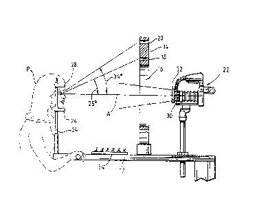
Figure l is a perspective view o a
photo-deviometer according to the present inve~tion.
Figure 2 is a front view of the photo-deviometer
of Figure 1.
Figure 3 is a side view of the photo-deviometer
of Figures l and 2 with a patient in posîtion.
Figures 4 and 5 are diagrams of the electrical
system of the photo-deviometer of Figures 1, 2, and 3.
Figure 6 is a view of the camera fi~ation device
and modified optics.
Description of Preferred Em~odimen~
Referring now to the drawings and particularly to
Figure l, the photo-deviometer is generally indicated by
. the rsference numeral 10 and includes a support structure
12, here shown as an adjustable tabl~. A deviometer disk
14 is mounted on the table 12 and i provided with a
~2230
centr31 fi~ation opening 16 and fi~ation images target 18
for deviometry measurements and fixation target or images
20 for extraocular dysunction measurement, here shown as
an inner row 18 and an outer row 20 o~ fi~ation images.
5 Mounted adjacent one end of the tablP 12 is a recording
device 22, here shown as a 35 mm camera, and mounted on
the other side of the deviometer disk 14 is an adjustable
headrest 24. The headrest 24 includes an adjustable chin
rest 26 and an adjustable forehead headrest 28 for fixing
10 the patient's head, not shown, so that the patient's eyes
are in a central fixation position with respect to the
central fixation opening 16 and the lens 30 of the
recording device 22 which is provided with the ring flash
32 mounted directly on the lens 30.
The inner and the outer row of fixation images 18
and 20 are positioned at the 12 o'clock, 1:30, 3:00, 4:30,
6:00, 7:30, 9:00 and ln: 30 positions.
As illustrated, recording device 22 is adjustable
mounted on the table 12 for aligning the lens 30 o~ the
20 camera in a central fi~ation position with respect to the
central fixation opening 16 and the plane of the film in
the camera.
Th~ deviometer or image wall 14 is provided with
images, not shown, positioned so that a patient can see
theiimages when they are illuminated. Preferablyi the
images selected are ~rom Walt Disney characters as the
cartoon figures are easily identifiable by most children
regardless of ethnic background and language barriers,
they are not violent, and these characters will probably
endure over future generations.
Also disposed on the table 12 are the selector
switches ~4 for selectively illuminating the visual images
on the inner and outer rows 18 and 20 of the deviometer
disk 14.
Referring now to Figures 4 and 5, an electrical
_9_ ~3~ ~23~
diagram is illustrated for illuminating the inner 18 and
outer 20 images by the electric bulbs 19 and 21,
respectively. Positive lines ~5 are con~ected to each of
the switches 34 and to each of the bulbs 19 and 21, which
5 in turn are connected to the ground 23. Thus, activation
of a switch 34 illuminates an image. No more description
of the electrical systems for illuminating the images 18
and 20 is given or deemed necessary as any desired
electrical system for this purpose can be used.
Referring now to Figure 2, the lens 30 of the
camera is located in the central portion of the central
fixation opening 16 of the disk 14. Referring now to
Figure 3, a Patient "P~ has her head adjusted by the
adjustable headrest 24 so that her eyes are directly in
15 line with the central fixation opening 16 to ths center of
the lens 30 of the camera 22. Thus, the Patient "P"
focuses on the film plane as opposed to some point in
between.
A 90 view finder is attached to the view finder
20 of the 35 mm SLR camera 22 which illuminates an
accommodative targe~, a car~oon character, which is viewed
by the Patient "P". This method of single illumination
accommodative target has ~een selected so as to attract
the patient's attention to that specific immage. This was
done especially due to the fact that the operator must
deal with young patients that often present with a low
attention span. Thus, this system provides true central
fixation. In the past, a single red diode mounted on the
top o~ a flash was positioned under the front portion of a
35 mm macrolens to serve as a central ~ixation target, but
this yielded inaccurat~ results fdrstly because it was a
nonaccommodative target. Secondly, the subject ended
looking at a ixation target that was too low and that was
22 cm away from the f ilm plane. The current central
ixabion device was made partially possible by using a
-lo- ~3~ 223~
number 9 endoscopic photo Fr~snel (a focusing screen from
the Olympus Corporation). rhe number 9 Fresnel has a
clear surface with its center, which is 23 mm in diameter,
acting as a -tl8 Diopter lens. This in turn magnifies the
5 image that is pro~ected ~rom the 90 view finder through
the SLR camera (22) and the macrolens system (30). Thus,
the Patient "P" focuses on the film plane as opposed to
some point in between and a true accommodative fixation
devi~e is provided. The image is introduce~ simply by
10 using the proper illumination switch. The image also can
be taken out of view by rotating a lever on the view
finder or simply ramoving the 90 view finder from the SLR
camera eyepiece.
In the presence of manifest strabismus, the
Patient "P" sees the image with only one eye and,
therefore, the fixating eye or the preferred eye should be
used to record accurate results. This can be achieved by
using the cover test system. As this image is being
projected to the Patient "P," the operator can depress
20 either a hand or foot switch and for one-sixtieth of a
second, the mirror of the 35 mm camera 22 pops up (the
image can no longer be seen) and the photograph of true
central fi~ation is achieved. At this point, the image
reappears to the patient until an alternate image is
selected on the fixation wheel or disk l4. When the
photograph is taken in this primary gaze, the light
illuminating the image is turned off for a period of
one-fiftieth of a second. This occurs so that the light
traveling through the prism head and lens coming ~rom the
90 view finder will not afect the automatic e~posure of
the SLR camera 22.
The camera 22 must, however, stay stationary,
that is at the same elevation as the 3 and 9 o'clock
fi~ation posi~ions to yield accurate and reproducible
results. Since the distance from the Patient "P" to the
r^~
3~2~3
1 lens 30 is fixed, it is not necessary to refocus between
patients.
As an e~ample of a photo-deviometer according to
the invention by which the foregoing advantagQous results
5 are achieved, a photo-deviometer 10 was constructed which
included an adjustable table 120 cm in length and 42 cm in
width. The circular wheel 14 with the inner and outer
rows of fi~ation targets 18 and 20 was 54 cm in diameter
with a 26.5 cm fi~ation opening 16 in the center. This
opening was made so that a 35 mm SLR camera equipped with
a ring flash could be positioned centrally on a mono pod
36. The visual images on the wheel 14 were mounted on the
back of a blackboard shaped to ~it the wheel 14 which was
positioned with strips of Velcro~onto the front part of
the wheel. The image wheel could be interchange~ for new
imayes at any time. The images selected, as previously
mentioned, were Walt ~isney characters.
The recording device 22 was an Olympus OM-4 35 mm
single lens reflex tSLR) camera with an autowinder sitting
20 on the monopod 36 and controlled either by a hand switch
or a foot switch. A foot switch is very useful when doing
a cover test or when photographing a down gaze wher~ both
hands of the operator may be necessary to hold the eyelids
of the patient open. Attached to the camera 22 was a 135
mm macrolens with a bellow extended to 17 cm. The f stop
was preset at F22 for good depth of field. If desired,
the camera can be fitted with a datapak that would imprint
on the film, praferably in the lower right hand corner,
the patient's identification number, the date or the time
of the day.
An Olympus T-10 ring 1ash with recycling flash
time of four seconds set on ASA 400 and the automatic
position was used which was mounted directly on the
macrolens 30 which was 52 mm in diameter~ Kodak
Ectachrome EL-400ASA film wi~h a preset speed of 1/60th on
*rrale ~IQrk
-12- ~ 3~2230
the camera was used.
Highly satisfactory, accurate and reproducible
measurements and photographs were obtained.
When performing deviometry measurements, the
5 operator normall~ sits on the let side when doing the
right gazes and on the right side when doing the left
gazes. When the photographs are taken, the same principle
applies. Care must be taken to ensure that the patient is
using the fixating eye when fixating at the different
accommodative targets. This can be easily accomplished
with the cover technique. The pediatric subject can be
measured in either the standing or sitting position, on
the parent's lap and, if older, in an e~amining chair. If
desired, for added accuracy, a special counting grid used
15 in endothelial cell photography can be used. This grid
has 2 mm squares. It is placed at the film plane of the
camera and will help to measure any eye deviation.
The photo-deviometer according to the present
invention allows both measurement and photographic
20 documentation of the strabismus in the cardinal positions
of gaze. The photo-deviometer may be operated by only one
person, be ~t the ophthalmologistJ ophthalmic
photographer, or other allied help professio~al. The
e~aminer can control the patient, the fi~ation target, and
the SLR camera all at the same time Since both
measurements and photographs are obtained simultaneously,
this instrument has proved to be a time saving device.
By using the ring flash~ the operator will
automatically produce a corneal specular reflection
simulating the ~irshberg test. This can be very useful in
evaluating one eye over the other.
Accordingly, the present invention attains the
objects and ends and has the advantages and features
mentioned as well as others inherent therein~
While presently preerred embodiments of the
-13- ~3~23~
invention have been given ~or the purpos2s of disclosure,
changes may be made therein which are within the spirit of
the invention as deined by the scope and the appended
claimsO
WHAT IS CLAIMED IS: