Note : Les descriptions sont présentées dans la langue officielle dans laquelle elles ont été soumises.
F.8087
t314193
BI-PETAL CHECK-VALVE CONSTRUCTION
BAC~GROUND OF THE INVENTION
This invention relates to a body construction for
a check valve or the like for carrying a fluid or fluid
flow and in particular to up-stop structure for the
respective members of a bi-petal check valve wherein
strong unidirectional surges of fluid flow must be
accommodated.
A check valve of the character indicated provides
a seat post which extends diametrically across the
section of flow accommodation in a pipe or conduit,
thus dividing the flow and providing two like opposed
generally semi-circular seat openings to share the
fluid flow. And separate valve members are hinged
back-to-back on a common axis parallel to and at down-
stream offset from the seat po~t, with provision forresiliently loading the valve members to their normal
seated position of closing the respective seat openings.
Sudden surges of fluid flow in the downstream direction
open the valve with such force that the valve members
can have mutually destructive impact unless measures
are taken for avoiding member-to-member contact upon
valve opening. And the prior art includes various such
; mea~ures, including independent valve-body upstop
referencing for each of the valve members (Patent No.
4,230,148), and torsion-spring retarders for the valve
members as they approach full-open position (Patent Nos.
4,351,358 and 4,249,567).
1 3 1 4 1 ~ 3 60538-1017
All of the up-stop or retarding structures of which I
am alware exhibit various deficiencies, not the least of which
is that their retarding or impact-resisting force is relatively
local, in application to the respective valve members. One may
generalize by observing that the prior-art structures have
relied upon essentially point contact with the opening valve
members, with the result that the momentum of opening valve
members must be asym~etrically absorbed, with ultimately
destructive effect upon the valve members and/or their hinging
and upstop structures.
BRIEF STATEMENT OF THE INVENTION
The present invention provides a check valve
comprising a cylindrically annular body which includes a
diametrically extending seat post dividing the opening of said
body into two like opposed generally semicircular valve-seat
openings to share fluid flow in a single downstream direction
through said body, and two valve members having hinge
suspension from said body to open and close said valve-seat
openings, said valve members being hinged on a common axis
parallel to and at downstream offset from said seat post,
diametrically opposed mount structures for said hinge
suspension and forming parts of said body, said mount
structures extending at downstream offset beyond the axis of
hinge suspension, and a diametrically extending upstop mounted
to and extending between the downstream offsets of said mount
structures, said upstop comprising a single cylindrically
arcuate member of stiffly compliant tempered steel wherein the
cylindrical arc is in the order of 3 radians, leaving a
stiffly compliantly closable gap of approximately ~ radians
between cylindrically arcuate limits, said upstop being
supported by said mount structures essentially only in a
circumferentially central region between said arcuate limits
`:,, ~,
1 3 1 ~ 1 93 6053~-1017
and with said gap in downstream-directed orientation.
Valve-member impact at and near the full-open
position can be compliantly absorbed with substar.tially
complete symmetry and uniformity over an extensive area, with
respect to the hinge suspension. The stiffly compliant member
provides essentially a continuous line of contact with the
downstream side of each valve member. This line of contact is
symmetrically located to span virtually the entire distance
between the spaced hinge-suspension points unique to each valve
member. Continuity of the respective lines of upstop contact
is maintained throughout a terminal range of angular
displacement, as the upstop compliantly deforms in approach to
the full-open condition of the respective valve members.
DETAILED DESCRIPTION
The invention will be described in detail for a
preferred embodiment and in connection with the accompanying
drawings, in which:
Figure 1 is a vertical sectional view of a bi-petal
check valve incorporating the upstop feature of the invention;
Figure 2 is a front elevation of the valve of Figure
1, namely, looking downstream in the direction of fluid-flow
accommodation, and indicating at 1-1 the section plane of
Figure l;
2a
r 1
1 3 1 4 1 93
Fig. 3 is a rear elevation of the valve of Fig. l;
Fig. 4 is a side elevation, taken from the aspect
designated 4-4 in Fig. 3;
Fig. 5 is a fragmentary left-and elevation of upstop-
mounting structure of Fig. 4; and
Fig. 6 is a perspective view of the upstop elementof t~e -~lve of Fig. 1.
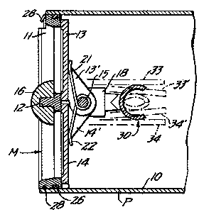
The check valve in which upstop structure of the
invention is embodied in Fig. 1 is of the modular nature
shown and described in Patent 4,257,444. Thus, a check-
valve module M is bodily insertable into one end of the
cylindrical bore 10 of a standard pipe or conduit P, to
determine one-way flow in the left-to-right direction of
Fig. 1. The check-valve module comprises a relatively
thin cylindrical body annulus 11 which has a cylindrical
outer surface designed for relatively close but slip-fit
reception in the bore 10. The inner-surface contour of
the body annulus 11 is smoothly convergent to a valve-
seat plane at the downstream end, and a diametrically
extending seat post 12, integrally formed with the body
annulus, extends diametrically across the annulus at the
seat plane, dividing the body opening into two like
opposed generally semicircular valve-seat openings A-B
(Fig. 2). Two like valve members or petals 13-14 have
offsetting arms 13'-14' by which they are independently
hinged from a single hinge pin 15 which extends diametri-
cally, at a location downwardly offset from the valve-seat
plane and parallel to the seat post 12. A semi-cylindrically
rounded flow deflector 16 is carried by the seat post, and
its diameter substantially conforms to the span between
valve members 13-14 when driven to open position.
Seated valve-member overlap of body 11-12 at the
seating plane is peripherally continuous about each of
the openings defined by the seat post 12, to the extent
designated ~1 in Fig. 3, thus leaving a radial clearance
~2 ~etween each petal 13 (14) and the adjacent cylindrical
periphery of the valve body '1. At the diametrically
opposite regions of seat-post juncture with body 11, the
clearance ~2 is slightly enlarged, for greater structural
integrity and to integrally accommodate local downstream
1 3 1 4 1 ~3
mounts 18-19 for the respective ends of hinge pin lS.
A single coil spring 20 wrapped around pin 15 is
characterized by tangent end arms 21-21' by which it
applies bias torque to urge valve members 13-14 to
the closed position shown. To secure and seal the
indicated slip-fit to bore ln, the external surface
of body 11 has a circumferential seal groove 23 near
the valve-seating plane, and a retainer groove 24 more
near the upstream end of body 11. An elastomeric
O-ring 26 in groove 23 has circumferentially sealing
engagement to the bore 10, and a retaining wire 28
is circumferentially accommodated by and between groove
24 and an undercut complementary groove in the bore 10,
for axial retention of the slip-fitted module M in pipe
P. Reference is made to said Patent No. 4,257,444 for
further detail of the retaining wire 28 and its removable
reception by grooves 23-24.
In accordance with the invention, a stiffly
compliant upstop 30 is supported by mounts 18-19 for
independent and substantially continuous line contact
with the respective valve members 13-14 as they near
their respective full-open positions; their relationship
at first contact with upstop 30 is shown by phantom lines
33-34 in Fig. 1, and by phantom lines 33l_34- when com-
pliant deformation of the upstop reaches an end. As bestseen in Figs. 4, 5 and 6, upstop 30 comprises an elongate
i4ndrical arc of spring steel, with narrow end projections
1 which are in welded seating relation to the conforming
cylindrically arcuate concavity of an upstop mount 38 (39),
which is in turn secured to and therefore forms part of
the respective hinge mounts 18 (19). For engagement with
the flat back side of valve member 13, the upstop 30
integrally comprises an arcuate wing 40 which in Fig. 3
is seen to substantially correspond to, and to be
symmetrically positioned between, the hinge arms 13' of
valve member 13; and for engagement with the flat back
side of valve member 14, upstop 30 further integrally
comprises an arcuate wing 41 which in Fig. 3 is seen to
substantially correspond to, and to be symmetrically
positioned between, the hinge arms 14' of valve member 14.
1 3 1 4 1 ~3
The upstop 30 is conveniently made from tubular
stock from which approximately ~7~ radians of cylindrical
arc have been removed, for the respective indicated lengths
of wings 40-41, thereby leaving approximately 3nr radians
as the combined cylindrically arcuate extent of wings 40-41.
At the outer end of each wing, the remaining length of the
upstop is reduced to define a narrow, axially projecting
arcuate tab 42 (43), by which to secure and support the
upstop via mounting means 18-38 (19-39).
It will be seen that each wing 40 (41) engages its
associated valve member 13 (14) along a straight line of
contact at substantial downstream offset from and parallel
to hinge pin 15, and that the open aspect of the upstop
faces downstream. The angular momentum and flow-driven
energy of a rapidly opening valve-member motion is
absorbed by stiffly compliant deformation of the wings
40-41, to a limiting extent denoted by phantom outlines
33'-34', at which point the outer ends of wings 40-41 abut,
and the compliantly deformed section 30' of upstop 30
resembles an ellipse. The stiff compliance assures stout
progressively increasing force development as valve members
may advance from the initial-contact positions 33-34 to
their limiting positions 33'-34', and this force development
is not only well distributed along straight lines of contact
with the respective valve members 13-14, but is also symmetri-
cally applied over virtually the entire span between the
pair of hinge arms 13' (14') for the respective valve
members. This relationship is achieved without increase
in the flow-accommodating envelope of the check valve.
_5_