Sélection de la langue

Search

Sommaire du brevet 1314363 

Énoncé de désistement de responsabilité concernant l'information provenant de tiers

Une partie des informations de ce site Web a été fournie par des sources externes. Le gouvernement du Canada n'assume aucune responsabilité concernant la précision, l'actualité ou la fiabilité des informations fournies par les sources externes. Les utilisateurs qui désirent employer cette information devraient consulter directement la source des informations. Le contenu fourni par les sources externes n'est pas assujetti aux exigences sur les langues officielles, la protection des renseignements personnels et l'accessibilité.

Disponibilité de l'Abrégé et des Revendications

L'apparition de différences dans le texte et l'image des Revendications et de l'Abrégé dépend du moment auquel le document est publié. Les textes des Revendications et de l'Abrégé sont affichés :

  • lorsque la demande peut être examinée par le public;
  • lorsque le brevet est émis (délivrance).
(12) Brevet: (11) CA 1314363
(21) Numéro de la demande: 1314363
(54) Titre français: SUPPORT POUR BALAI A LAVER
(54) Titre anglais: MOP HOLDER
Statut: Périmé et au-delà du délai pour l’annulation
Données bibliographiques
(51) Classification internationale des brevets (CIB):
  • A47L 13/24 (2006.01)
  • B25G 3/30 (2006.01)
(72) Inventeurs :
  • FRIEDMAN, HERBERT D. (Canada)
  • FRIEDMAN, MARK A. (Canada)
(73) Titulaires :
  • MANN BRUSH MANUFACTURING LTD.
(71) Demandeurs :
  • MANN BRUSH MANUFACTURING LTD. (Canada)
(74) Agent: NORTON ROSE FULBRIGHT CANADA LLP/S.E.N.C.R.L., S.R.L.
(74) Co-agent:
(45) Délivré: 1993-03-16
(22) Date de dépôt: 1989-03-02
Licence disponible: S.O.
Cédé au domaine public: S.O.
(25) Langue des documents déposés: Anglais

Traité de coopération en matière de brevets (PCT): Non

(30) Données de priorité de la demande:
Numéro de la demande Pays / territoire Date
312,470 (Etats-Unis d'Amérique) 1989-02-21

Abrégés

Abrégé anglais


ABSTRACT
A mop holder for a yarn-type mop head
comprises a shank which is adapted for connection to
a mop handle and an elongated member which has a
threaded rod extending therefrom. The threaded rod
includes an upper and a lower part. The lower part
which is larger than the upper part is located
intermediate the elongated member and this upper
part. A nut is provided for engagement with the
lower part of the threaded rod whereas the shank is
adapted with an inner sleeve for screwable
engagement thereof with the upper part of the
threaded rod. The mop head comprises a grommet
defined therein that is of larger transverse
dimension than that of the lower part of the rod for
being positioned therearound. Therefore the mop
head is secured to the mop holder by way of the nut
which is engaged in the rod while the shank ensures
tightness of the nut.

Revendications

Note : Les revendications sont présentées dans la langue officielle dans laquelle elles ont été soumises.


The embodiments of the invention in which
an exclusive property or privilege is claimed are
defined as follows:
1. A mop holder for a yarn-type mop head
comprises a shank including a tubular sidewall, a
bottom wall at a lower end of said sidewall and a
threaded sleeve extending substantially at right
angles from said bottom wall inside said shank, at
least an upper part of said sidewall being adapted
for connection to a mop handle; an elongated member
having a threaded rod extending generally at right
angles therefrom and intermediate thereof wherein
the elongated member defines a pair of shoulders on
either side of the rod, said rod comprising first
and second threaded parts, said second threaded part
being located intermediate said elongated member and
said first threaded part, said second threaded part
being of larger diameter than said first threaded
part, said mop head defining an opening of larger
diameter than said second threaded part of said rod
for being positioned therearound; and a mop head
retaining member including a threaded opening
defines therethrough being adapted for threadably
engaging said second threaded part of said rod
whereas said sleeve of said shank is adapted for
threadably engaging said first threaded part of said
rod, whereby said mop head is secured to said mop
holder by way of said mop head retaining member
cooperating with said elongated member.
2. A mop holder as defined in Claim 1,
wherein said mop head comprises a webbing
transversely mounted thereto around a middle section
thereof, said opening of said mop head being further

defined through said webbing and being adapted with
a grommet.
3. A mop holder as defined in Claim 2,
wherein an upper surface of said elongated member at
least partly underlies said webbing of said mop
head, said rod extending from said upper surface.
4. A mop holder as defined in Claim 3,
wherein said elongated member also comprises a
number of pointed teeth integral thereto and
extending from said upper surface thereof through
said webbing into said middle section of said mop
head for providing further substantially lateral
restraint of said mop head on said elongated member.
5. A mop holder as defined in Claim 2,
wherein said grommet is made of brass.
6. A mop holder as defined in Claim 2,
wherein said mop head retaining member is an
oversized nut at most as large as said webbing
whereby said mop head is urged against said
elongated member by said nut whereas said shank
abuts said nut for ensuring tightness thereof.
7. A mop holder as defined in Claim 1,
wherein said second threaded part of said rod
substantially adjoins said first threaded part
thereof.
8. A mop holder as defined in Claim 1,
wherein said shank, said elongated member and said
mop head retaining member are made of a plastic
material.

9. A mop holder as defined in Claim 1,
wherein at least one opening is defined in said
upper part of said sidewall of said shank for
receiving a nail to secure the mop handle to said
shank.

Description

Note : Les descriptions sont présentées dans la langue officielle dans laquelle elles ont été soumises.

1 3 1 ~363
The present invention relates to mop
holders and, more particularly, to mop holders for
replaceable yarn-type mop heads.
Most mop holders for replaceable mop heads
presently use one of the two following general
systems. In the guillotine-type system which is
disclosed, for example, in U.S. Patent Nos.
4,287,632 and 4,422,203, a hinged bar is closed
against a retaining bar of the mop holder thereby
fixing the mop head therewithin. It is common,
using this system, that the hinged bar opens up
under strain thereby releasing the mop head.
In the plier-type mechanism, which is
disclosed, for instance, in U.S. Patent Nos.
3,496,616 and 3,813,724, a first jaw, a spriny-uryed
second jaw and a lever adapted to open the preceding
jaws cooperate for holding a mop head within the
confines thereof. This system, as well as the above
described guillotine-type system, is costly.
~, It is therefore an aim of the present
invention to provide a mop holder having a simple
construction and, thus, lower cost.
It is a further aim of the present
invention to provide a mop holder in which a mop
head remains secured thereto even under heavy usage.
Therefore, in accordance with the present
invention, there is provided a mop holder for a
yarn-type mop head which comprises a shank including
a tubular sldewall, a bottom wall at a lower end of
the sidewall and a threaded sleeve extending
sub6tantially at right angles from the bottom wall
inside the shank. At least an upper part of the
sidewall is adapted for connection to a mop handle.
An elongated member has a threaded rod extending
generally at right angles therefrom and intermediate
thereof wherein the elongated mem~er defines a pair
-2-
,, .

3 6 3
of shoulders on either side of the rod. The rod
compxises first and second threaded parts. The
second threaded part is located intermediate the
elongated member and the first threaded part. The
second threaded part is of larger diameter than the
L irs t threaded part. The mop heacl defines an
opening of larger diameter than the second threaded
part of the rod for being positioned therearound. A
mop head retaining member including a threaded
opening defined therethrough is adapted for
threadably engaging the second threaded part of the
rod whereas the sleeve of the shank is adapted for
threadably engaging the first threaded part of the
rod. The mop head is thus secured to the mop holder
by way of the mop head retaining member cooperating
with the elongated member.
Another construction in accordance with
the present invention comprises a mop holder for a
yarn-type mop head having a shank means which is
adapted for connection to a mop handle. A mop head
retaining means includes at least an elongated
member which has a threaded rod extended therefrom.
The shank means is adapted for screwable engagement
thereof with the threaded rod. The mop head defines
an opening which is of larger transverse dimension
than that of the threaded rod for being positioned
-2a-
~..

~ 31 ~3~3
therearound. The mop head is thus secured to the mop
holder by way of the shank means cooperating with the
mop head retaining means.
In a further aspect of the present
invention the threaded rod comprises first and second
sections. The second section is located intermediate
the elongated member and the first section. The
second section is of larger transverse dimension than
the first section, the second section substantially
adjoining the first section. The first and second
sections are also adapted for screwable engagement
thereof respectively with the shank means and with a
nut means. The mop head is therefore urged against
the elongated member by way of the nut means whereas
the shank means ensures tightness thereof.
In a still further aspect of the present
invention, the mop retaining means also comprises a
number of pointed tooth means extending from the
elongated member in the same direction as the
threaded rod into a middle section of the mop head.
The tooth means puncture a lining means transversely
extending from the middle section of the mop head, as
-tips of the tooth means are positioned in the mop
head for providing further substantially lateral
restraint of the mop head on the elongated member.
Having thus generally described the nature
of the invention, reference will now be made to the
accompanying drawings, showing by way of illustration
a preferred embodiment thereof, and in which:
Fig. 1 is a perspective view of a mop
holder in accordance with the present invention
provided with a yarn-type mop head;
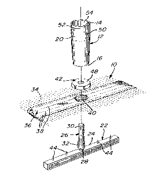
Fig. 2 is an exploded view showing how the
mop head is mounted to the mop holder;
Fig. 3 is a side view shown partly in
cross-section illustrating the mop head mounted to
the mop holder; and
-- 3
,: ,

3 6 3
Fig. 4 is an elevation shown partly in
cross-section illustrating the mop head mounted to
the mop holder.
In Fig. 1, a mop holder H is shown with a
disposable mop head 10 mounted thereto. The mop head
10 is made of yarn.
Now referring mainly to Figs. 3 and 4, a
plastic or metal shank 12 of circular cross-section
has an open upper end 14 and a lower end 16. A
threaded sleeve 18 is defined centrally and
longitudinally in the shank 12 from the lower end 16
thereof. The upper hollow section 20 of the shank 12
is adapted for receiving a lower end of a standard
~mop handle, which is not shown.
;A plastic elongated member 22 of
- rectangular cross-section includes an upper surface
24. A threaded rod 26, integral at a lower end 28
thereof to the elongated member 22, extends at right
angles from the middle of the upper surface 24 of the
member 22. The elongated member 22 and the threaded
rod 26 can thus be manufactured from a same mold.
The rod 26 comprises first and second
threaded sections 30 and 32 respectively. The first
threaded section 30 is of smaller diameter than that
of the second threaded section 32.
The mop head 10 comprises yarns 34
maintained in a unit by way of a lining 36 and of
stitchings 38. The yarns 34 are maintained to the
lining 36 substantially at their middle, as best seen
in Fig. 1.
A brass grommet 40 is press-fitted into the
lining 36 at the middle thereof. The grommet 40 is
of larger diameter than that of the second threaded
section 32 of the rod 26. The mop head 10 has a
transverse dimension substantially equal to the
longitudinal dimension of the elongated member 22 for
overlying the elongated member 22 once the grommet 40
; -4-

131~363
.
has heen slidably positioned around the lower end 28
of the threaded rod 26. An oversized nut 42, made
of hard plastic, is adapted for screwable engagement
thereof with the second threaded section 32 of the
rod 26. The longitudinal dimension of the second
threaded section 32 is provided with respect to the
thickness of the mop head 10 in order that the
oversized nut 42 can be screwed onto the second
threaded section 32 for exerting pressure on the
grommet 40 and on a section of the lining 36 aro~nd
the grommet 40 and underlying the oversized nut 42.
rrhe mop head 10 is thus secured to the mop holder H.
Additional lateral stability of the mop
head 10 on the elongated member 22 is achieved by a
number of pointed teeth 44 extending from the upper
surface 24 of the elongated member 22. The pointed
teeth 44 puncture through the lower section 46 of
the lining 36 and partly through the yarns 34 of the
mop head 10, as best seen in Fig. 4, for restraint
thereof.
The shank 12 is screwed onto the first
threaded section 30 of the rod 26 and abuts a top
surface 48 of the nut 42 for enhancing tightness
thereof.
The handle of the mop is longitudinally
and laterally secured to the shank 12 by way of a
nail or the like planted in the handle through an
opening 50 defined in a wall 52 of the upper hollow
section 20 of the shank 12.
It can be easily seen that the present
invention offers a mop holder H having a simple
construction and thus a low cost. Furthermore, the
mop holder H is sturdy and the mop head 10 is well
secured thereto thus ensuring efficiency under heavy
usage.
_5_
. . . .
,

3 6 3
The invention being thus described, it
will be obvious that the same may be varied in many
ways. Such variations are not to be regarded as a
departure from the spirit and scope of the
invention, and all such modifications as would be
obvious to one skilled in the art are intended to be
included within the scope of the following claims.
~ '
:,
:~;
:~
~ ::
-6-

Dessin représentatif
Une figure unique qui représente un dessin illustrant l'invention.
États administratifs

2024-08-01 : Dans le cadre de la transition vers les Brevets de nouvelle génération (BNG), la base de données sur les brevets canadiens (BDBC) contient désormais un Historique d'événement plus détaillé, qui reproduit le Journal des événements de notre nouvelle solution interne.

Veuillez noter que les événements débutant par « Inactive : » se réfèrent à des événements qui ne sont plus utilisés dans notre nouvelle solution interne.

Pour une meilleure compréhension de l'état de la demande ou brevet qui figure sur cette page, la rubrique Mise en garde , et les descriptions de Brevet , Historique d'événement , Taxes périodiques et Historique des paiements devraient être consultées.

Historique d'événement

Description Date
Inactive : CIB de MCD 2006-03-11
Lettre envoyée 2005-09-26
Le délai pour l'annulation est expiré 2005-03-16
Lettre envoyée 2004-03-16
Accordé par délivrance 1993-03-16

Historique d'abandonnement

Il n'y a pas d'historique d'abandonnement

Historique des taxes

Type de taxes Anniversaire Échéance Date payée
TM (catégorie 1, 5e anniv.) - générale 1998-03-16 1998-03-04
TM (catégorie 1, 6e anniv.) - générale 1999-03-16 1999-02-15
TM (catégorie 1, 7e anniv.) - générale 2000-03-16 2000-02-22
TM (catégorie 1, 8e anniv.) - générale 2001-03-16 2001-03-12
TM (catégorie 1, 9e anniv.) - générale 2002-03-18 2002-02-21
TM (catégorie 1, 10e anniv.) - générale 2003-03-17 2003-01-23
Enregistrement d'un document 2004-05-13
Titulaires au dossier

Les titulaires actuels et antérieures au dossier sont affichés en ordre alphabétique.

Titulaires actuels au dossier
MANN BRUSH MANUFACTURING LTD.
Titulaires antérieures au dossier
HERBERT D. FRIEDMAN
MARK A. FRIEDMAN
Les propriétaires antérieurs qui ne figurent pas dans la liste des « Propriétaires au dossier » apparaîtront dans d'autres documents au dossier.
Documents

Pour visionner les fichiers sélectionnés, entrer le code reCAPTCHA :


Pour visualiser une image, cliquer sur un lien dans la colonne description du document. Pour télécharger l'image (les images), cliquer l'une ou plusieurs cases à cocher dans la première colonne et ensuite cliquer sur le bouton "Télécharger sélection en format PDF (archive Zip)" ou le bouton "Télécharger sélection (en un fichier PDF fusionné)".

Liste des documents de brevet publiés et non publiés sur la BDBC .

Si vous avez des difficultés à accéder au contenu, veuillez communiquer avec le Centre de services à la clientèle au 1-866-997-1936, ou envoyer un courriel au Centre de service à la clientèle de l'OPIC.


Description du
Document 
Date
(aaaa-mm-jj) 
Nombre de pages   Taille de l'image (Ko) 
Dessins 1993-11-10 1 52
Page couverture 1993-11-10 1 14
Revendications 1993-11-10 3 91
Abrégé 1993-11-10 1 25
Description 1993-11-10 6 211
Dessin représentatif 2000-08-14 1 17
Avis concernant la taxe de maintien 2004-05-11 1 173
Courtoisie - Certificat d'enregistrement (document(s) connexe(s)) 2005-09-26 1 104
Taxes 1997-02-17 1 55
Taxes 1996-03-04 1 58
Taxes 1995-03-15 1 55
Demande de l'examinateur 1991-10-24 1 50
Correspondance de la poursuite 1992-02-24 3 86
Correspondance reliée au PCT 1992-12-16 1 30