Sélection de la langue

Search

Sommaire du brevet 1314783 

Énoncé de désistement de responsabilité concernant l'information provenant de tiers

Une partie des informations de ce site Web a été fournie par des sources externes. Le gouvernement du Canada n'assume aucune responsabilité concernant la précision, l'actualité ou la fiabilité des informations fournies par les sources externes. Les utilisateurs qui désirent employer cette information devraient consulter directement la source des informations. Le contenu fourni par les sources externes n'est pas assujetti aux exigences sur les langues officielles, la protection des renseignements personnels et l'accessibilité.

Disponibilité de l'Abrégé et des Revendications

L'apparition de différences dans le texte et l'image des Revendications et de l'Abrégé dépend du moment auquel le document est publié. Les textes des Revendications et de l'Abrégé sont affichés :

  • lorsque la demande peut être examinée par le public;
  • lorsque le brevet est émis (délivrance).
(12) Brevet: (11) CA 1314783
(21) Numéro de la demande: 1314783
(54) Titre français: DISPOSITIF PARE-FEU
(54) Titre anglais: FIRE ISOLATION DEVICE
Statut: Périmé et au-delà du délai pour l’annulation
Données bibliographiques
(51) Classification internationale des brevets (CIB):
  • F16K 17/36 (2006.01)
  • A62C 02/06 (2006.01)
  • F16K 17/38 (2006.01)
(72) Inventeurs :
  • FRIEND, ALDEN EMERSON (Etats-Unis d'Amérique)
  • DUNHAM, LAWRENCE ALLEN (Etats-Unis d'Amérique)
(73) Titulaires :
  • ITT CORPORATION
(71) Demandeurs :
  • ITT CORPORATION (Etats-Unis d'Amérique)
(74) Agent: SMART & BIGGAR LP
(74) Co-agent:
(45) Délivré: 1993-03-23
(22) Date de dépôt: 1989-09-25
Licence disponible: S.O.
Cédé au domaine public: S.O.
(25) Langue des documents déposés: Anglais

Traité de coopération en matière de brevets (PCT): Non

(30) Données de priorité de la demande:
Numéro de la demande Pays / territoire Date
302,506 (Etats-Unis d'Amérique) 1989-01-26

Abrégés

Abrégé anglais


PATENT
Friend 1 - 3
FIRE ISOLATION DEVICE
ABSTRACT OF THE INVENTION
A fire isolation device having a valve designed to close
after a given temperature has been reached by a fusible nose
member in the form of a sleeve of fusible material. The device
has a passageway therethrough and a self-closing valve member
having a poppet and a seat disposed in the passageway with the
poppet being biased toward the seat to a valve closed position.
At least one aperture through the nose member provides for
continuous fluid flow through the device around the poppet and
the seat. The nose member is positioned to hold the valve in an
open position against the bias on the poppet. The seat has a
flow path on its outer end dimensioned to fit the nose member
and a flow path towards its inner end larger in diameter than
the nose member in an area occupied by the aperture to permit
flow therethrough when the nose member holds the valve in an
open position. The nose member is made of a material designed
to melt in the neighborhood of 700° F when the fire isolation
device is exposed to 2000° F for 15 minutes, for example, after
which it will collapse into the larger diameter permitting the
bias to close the valve. The nose member is designed to melt
prior to an attached component in order to prevent fluid leakage
at the component. The remainder of the parts of the device are
made of a higher temperature resistant material.
In a second embodiment a bi-directional device is provided
in which valve and nose members are positioned in both ends
thereof.

Revendications

Note : Les revendications sont présentées dans la langue officielle dans laquelle elles ont été soumises.


72432-47
THE EMBODIMENTS OF THE INVENTION IN WHICH AN EXCLUSIVE
PROPERTY OR PRIVILEGE IS CLAIMED ARE DEFINED AS FOLLOWS:
1. A fire isolation device capable of operating at high
temperatures such as 2000° F. for up to 15 minutes, the device
having a passageway therethrough, a self closing valve having a
stainless steel poppet and a stainless steel seat disposed in said
passageway with said poppet mechanically biased toward said seat
to a valve closed position closing the passageway through the
device, a nose member in the form of a sleeve of fusible material
having at least one aperture therethrough to provide a continuous
fluid flow path through said device around said poppet and through
said seat and being positioned to hold said valve in an open
position against the bias on the poppet, said seat having a flow
path on its outer end dimensioned to fit said nose member and a
flow path towards its inner end larger in diameter than said nose
member in the area occupied by said at least one aperture to
permit flow therethrough when said nose member holds said valve in
an open position, said nose member being of a material to melt
prior to the melting of an attached component after which the nose
member will collapse into said larger diameter permitting said
bias to close the valve and the remainder of the parts of the
device being made of higher temperature resistant material.
2. The device of claim 1 in which said nose member is made
of polyetheretherketone thermoplastic.
- 7 -

72432-47
3. A bidirectional fire isolation device capable of opera-
ting at high temperatures such as 2000° F. for up to 15 minutes,
the device having a passageway therethrough, a self-closing valve
having a stainless steel poppet and a stainless steel seat dispos-
ed in each end of the passageway with each poppet mechanically
biased towards its seat to a valve closed position closing the
passageway through the device, a nose member in the form of a
sleeve of fusible material in each end of said device having at
least one aperture therethrough to provide a continuous flow path
through said device around said poppet and through said seat and
each being positioned to hold its respective valve in an open
position against the bias on the poppet, each seat having a flow
path on its outer end dimensioned to fit its nose member and a
flow path towards its inner end larger than the diameter of its
nose member in the area occupied by said at least one aperture to
permit flow therethrough when its nose member holds the valve in
an open position, the nose members being of a material to melt
prior to the melting of an attached component after which the nose
members will collapse each into their adjacent larger diameter of
their valve seats permitting said bias to close the valves and the
remainder of the parts of the device being made of higher tempera-
ture resistant material.
4. The device of claim 3 in which said nose members are
made of polyetheretherketone thermoplastic.
- 8 -

72432-47
5. The device of claim 3, wherein said valve is not affect-
ed by vibration and shock.
6. A fire isolation device for mounting in a fluid line to
prevent fluid flow through the device when exposed to a high
temperature such as 2000°F. for 15 minutes, said device comprising
in combination:
a housing having a fluid passageway therethrough;
a poppet and a seat disposed in said passageway;
bias means for mechanically biasing said poppet toward
said seat to a closed position for closing said passageway;
a fusible nose member having at least one aperture
therethrough to permit fluid flow through said aperture, said nose
member being positioned to hold said poppet in an open position
against the bias on said poppet;
said seat having an outer end diameter dimensioned to
fit said nose member and an inner end diameter larger than said
outer end diameter, so that when said nose member holds said valve
poppet in an open position, fluid flow is permitted through the
nose member aperture toward its inner end diameter; and
said nose member being of a material which melts at a
temperature lower than the melting temperature of the material
forming said poppet, seat, housing, and bias means, whereby when
said nose member melts it collapses causing said poppet to seat on
said seat closing said passageway to prevent fluid flow there-
through.
- 9 -

72432-47
7. The combination according to claim 6 wherein said hous-
ing, poppet, and seat are made of stainless steel.
8. The combination according to claim 7 wherein said nose
member is made of polyetheretherketone thermoplastic.
9. The combination according to claim 8 wherein said bias
means is a compression spring positioned between a shoulder in the
passageway of said housing and said poppet.
10. The combination according to claim 9 wherein said hous-
ing has exterior threads at each end for mounting directly in said
fluid line.
11. A bidirectional fire isolation device for mounting in a
fluid line to prevent fluid flow through the device when exposed
to a high temperature such as 2000° F. for 15 minutes, said device
comprising in combination:
a housing having a fluid passageway therethrough;
a poppet and associated seat disposed in each end of
said passageway;
bias means for mechanically biasing said poppet in each
end toward its associated seat to a closed position for closing
said passageway;
a fusible nose member in each end of said passageway
having at least one aperture therethrough to permit fluid flow
- 10 -

72432-47
through said aperture, each said nose member being positioned to
hold said poppet in a respective end in an open position against
the bias on said poppet;
each said associated seat having an outer end diameter
dimensioned to fit said nose member, and an inner end diameter
larger than said outer end diameter, so that when each said nose
member holds said poppet in the respective end in an open posi-
tion, fluid flow is permitted through each nose member aperture
and said passageway; and
each said nose member being of a material which melts at
a temperature lower than the melting temperature of the material
forming said poppet, seat, housing, and bias means, whereby when
either said nose member melts it collapses causing said poppet in
the respective end to seat on its associated seat -to prevent fluid
flow through the device.
12. The combination according to claim 11 wherein said hous-
ing, poppet, and seat are made of stainless steel.
13. The combination according to claim 12 wherein said nose
member is made of polyetheretherketone thermoplastic.
14. The combination according to claim 13 wherein said bias
means is a compression spring positioned between each said poppet.
15. The combination according to claim 14 wherein said
- 11 -

72432-47
housing has exterior threads at each end for mounting directly in
said fluid line.
16. Apparatus comprising in combination:
a housing having a passageway therethrough;
an end seat fitted to at least one end of said housing,
said seat including an inside diameter portion, a larger diameter
portion, and a beveled portion;
a sleeve shaped fusible nose member having an aperture
therethrough, one end of said nose member being fitted to said
inside diameter and the other end being adapted to mount a poppet;
a compression spring mounted in said passageway to bias
said poppet toward said end seat, said poppet being prevented from
closing on said seat by said nose member; and
said nose member being of a material that melts at a
temperature lower than the melting temperature of the material
forming said housing, end seat, poppet, and compression spring,
whereby when said nose member melts it collapses into the area of
said larger diameter portion permitting said compression spring to
close said poppet against said beveled portion of said end seat to
prevent fluid flow through said passageway when said apparatus is
exposed to an elevated temperature of about 2000° F. for about 15
minutes.
17. The combination according to claim 16 wherein said
housing, poppet and seat are made from 316L stainless steel.
- 12 -

72432-47
18. The combination according to claim 16 wherein said nose
member is made of polyetheretherketone plastic.
19. The combination according to claim 16 wherein said hous-
ing has exterior threads at each end for mounting in apparatus in
a fluid flow line.
20. The combination of claim 16, wherein said apparatus is
not affected by vibration and shock.
- 13 -

Description

Note : Les descriptions sont présentées dans la langue officielle dans laquelle elles ont été soumises.

P,`' TF;;i r
Friend 1-3
` 131~7~3
FIRE ISOLATION DEVICE
BACKGROUND OF THE INVENTION
Field of the Invention
This invention rel~tes to a fire isolation device ~hich is
biased to close upon reaching a given temperature and more
particularly to such a device including a fusible member holding
a self-closing valve open prior to reaching the given tempera-
ture.
_escription of the Prior Art
U.S. Patent No. 3,245,423 Hansen, et al.; U.S. Patent No.
195,367 Hiller; U.S. Patent No. 1,930,624 Ryan and U.S. ~atent
No. 2, 048,387 Johnsen all relate to valve couplings with fusible
safety cutoff means. These devices are generally for lower
temperature applications than that of the subject inventlon and
all employ the use of a fusible material around the outside
diameter of a member such that when the material melts the
member moves permitting a biased poppet to close a valve. They
are used for applications such as boiler protection.
Another group of patents, U.S. Patent No. 2,305,841
Carlson, U.S. Patent No. 2,434,167 Knoblauch and U.S. Patent No.
2,850,297 Clark disclose quick disconnect couplers which are
designed to prevent loss of fluid flow when the coupling is
disconnected. These devices employ no fusible materials.
U.S. Patent No. 3,659,624 Kelly, et al., No. 3,842,35
Kelly, et al. and No. 3,896,835 Wicke all disclose gate valve~.
Kelly, et al. 624 employs a locking ring 50 of fusible material
which when upon melting allows expansion of the locking fingers
52 permitting the gate valve to close. Kelly, et al. 853
employs a fusible disk 173 which upon melting is extruded
through the port 171 permitting the piston member to close the
gate valve. Wicke employs a similar structure. None of these
last three references employ a fusible nose member in the flow
path through the gate valve.
U.S. Patent No. 3,618,627 Wagner discloses a temperature
responsive pressure relief employiny a fusible material behind

P~TE~IT
Friencl 1-'
7 ~ 3
a spring biased poppet which opens upon over temperature.
U.S. Patent No. 4,22~,760 Grirfith, et al. discloses a
pressure responsive valve which closes when plug 54 melts b~
means of fluid pressure such that there is some loss of fluid
5 prior to closure.
In accordance with an aspect of the present invention, it
is an object to provide a new ~nd im~roved ~ir~ ol;~t i~
device capable of operating at high temperatures such as 2000'
F for up to 15 minutes which employs a fusible member through
which the fluid normally flows which biases a valve poppet open.
Another object is to provlde such a device which is bi-
directional, having a valve member held open by a fusible nose
member in both ends thereof.
SUMMARY OF THE INVENTION
The foregoing and other objects are accomplished by
providing a fire isolation device having a passageway there-
through with a self-closing valve having a poppet and sea-t
disposed in the passageway, the poppet being biased toward t~e
~0 seat. A no.,e member in the form of a sleeve of fusible material
having at least one aperture therethru to provide a conti~)uous
fluid flow path thru the device is positioned to hold the poppet
open. The flow path in the outer end of the seat is dimensioned
to fit the nose member and the flow path towards its inner end
is larger in diameter than the nose member in the area occupled
by the aperture through the nose member to permit flow t~ere-
through when the nose member holds the valve in an open posi-
tion. The nose member is made of a material designed to melt- in
the neighborhood of 700 F when the device is exposed to 2000~ F
for 15 minutes, for example, after which it will collapse into
the larger diameter permitting the bias to close the valve prior
to any attached component melting, at for example, 1200 F,
preventing fluid loss thru the component. The remainder of the
parts of the device are made of a higher temperature resistant
material.

PATE~JT
F'riend 1-
- ~ 3 ~ 3
In a second embodiment valve members and nose members are
positioned in both ends of a device in the manner described
above.
Other objects, features and advantages of the invention
will become apparent from a reading of the specification when
taken in conjunction with the drawings in which like reference
numerals refer to like elements in the various views.
BRIEF DESCRIPTION OF THE DRAWINGS
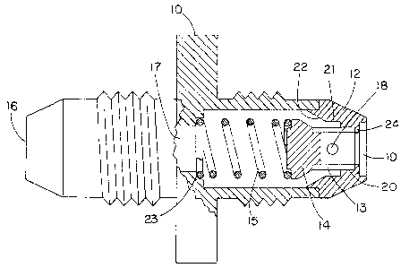
FIG. 1 is a partially cut-away side view of an embodiment
of the device of the subject invention designed for unitary
flow, and
FIG~ 2 is a cut-away side view of the device of the subject
invention employing valve members in both ends thereof.
DESCRIPTION OF THE PREFERRED EMBODIMENT
The device of the subject invention is designed to prevent
the fueling of fire by fluids of a system pressure line. ~'hen
exposed to a high temperature flame such as 2000 F for 15
minutes the device will isolate line fluid from the fire prior
to leakage and melting of any component to which it is cor.nected
and may be designed to be interchangeable for instance with an
AN815 fitting.
Referring to FIG. 1 the fire isolation device consists of
a housing 10, an end seat 12, a nose member of fusible material
13, a valve poppet 14 and a compression spring 15. Housing lC,
end seat 12, and poppet 14 may be made of 316L stainless steel.
Fusible nose member 13 may be mads from thermoplastic ! flA
example, polyetheretherketone ther~oplastic (peek). ~'nd~r
normal operation the fluid flows in the entrance 15 to the
device through the center aperture 17 around the spring 15 pas~
the poppet 14 and through the nose member 13 through an aperture
18 therein and out the port 19. Spring 15 seats against a
shoulder 23 in housing 10. The nose member 13 is positioned
snugly in the inside diameter 20 on the outer end of seat 12 and
up against a flange 24 on end seat 12 which is integral there-
with and has the same inside diameter as nose member 13. Seat
- ,

P."T E ~"r
Friend 1-3
i3~7g3
12 has a larger diameter 21 at its inner end through which the
fluid normally flows to get to the aperture 18 and out port 19.
The de~ice is designed to operate on exposure to elevatecl
temperature ~f ahout 2000 F for about 15 m~nutes, for example.
The fusible nose member 20 will melt upon reaching 700 F and
allow the spring loaded poppet 14 to close preventil-g fluid
leakage thru any attached component, not shown, which may melt
at 1200 F, for example. The fusible nose member 13 will
collapse into the larger diameter 21 and the poppet will seat
against the beveled portion 22 of seat 12.
Thus, any component such ~s ~n ~ minum i nC;t r~lm~!llt wl) ~
might be attached to output port 19 will melt at approximately
1218 F but the poppet 14 will close off the fuel source, not
shown, attached to input port 16 preventing fuel from entering
the area of the fire.
FIG. 2 discloses a bi-directional device in which the
fitting 11 which has a single inside diameter and no shoulder 23
such as used in FIG. 1, employs nose members 12 on both ends
thereof, each having its corresponding poppet 14 and fusible
nose member 13. A common spring biases both poppet mem~ers 14
toward thei- respective seats.
The device of~the subject invention is mechanically biased
and operated as opposed to the prior art Griffith patent r~hich
is pressure operated and permits some leakage. The subject
device prevents leakage by closing mechanically prior to failure
of an attached component preventing loss of system fluid whereas
the Griffith prior art device allows loss of system fluid ~ntil
sufficient fluid flow under pressure occurs to create enough
pressure drop across the poppet to cause closùre.
The subject invention is a stand alone design requiring no
outside mechanical influence for proper operation and functions
in all positions with no effect on performance. The subject
invention is designed to be used in any component or in iine
system application and is designed with single and dual poppet
versions. The dual poppet version cannot be installed backwards
:
,
:

P~TE~
Friend 1-~
1 31~g3
and operates the same in either flow directlon. The subject
invention is not affected by vibration and shock.
Because of weight and cost many aircraft components are
made of materials that cannot meet the fireproof (2000 F flame
for 15 minutes) or even fire resistant (2000 F flame for 5
minutes) requirements. It is necessary to protect suc.~ com-
ponents so that when a fire takes place there will not be fluid
loss through the components, thus the application for the
subject invention in fire protection of hydraulic systems, fluid
systems, lube oil systems and components for aircr~t en~ es
and other airborne applications. Other applications may inc]ude
military, equipment, tanks, trucks, buses, submarines, aircraft
carriers and all types of ships as well as radar systems for the
military commercial and industrial applications. Other possible
uses include chemical plants and processing systems, refineries
and other fuel and oil processing plants.
While particular embodiments of the invention have been
described, it will be understood of course that it is not
intended to limit the invention thereto since many modifications
may be made. It is therefore contemplated by the appended
claims to cover any such modifications as fall within the true
spirit and scope of the invention.
- `
`

Dessin représentatif
Une figure unique qui représente un dessin illustrant l'invention.
États administratifs

2024-08-01 : Dans le cadre de la transition vers les Brevets de nouvelle génération (BNG), la base de données sur les brevets canadiens (BDBC) contient désormais un Historique d'événement plus détaillé, qui reproduit le Journal des événements de notre nouvelle solution interne.

Veuillez noter que les événements débutant par « Inactive : » se réfèrent à des événements qui ne sont plus utilisés dans notre nouvelle solution interne.

Pour une meilleure compréhension de l'état de la demande ou brevet qui figure sur cette page, la rubrique Mise en garde , et les descriptions de Brevet , Historique d'événement , Taxes périodiques et Historique des paiements devraient être consultées.

Historique d'événement

Description Date
Inactive : CIB de MCD 2006-03-11
Le délai pour l'annulation est expiré 2005-03-23
Lettre envoyée 2004-03-23
Accordé par délivrance 1993-03-23

Historique d'abandonnement

Il n'y a pas d'historique d'abandonnement

Historique des taxes

Type de taxes Anniversaire Échéance Date payée
TM (catégorie 1, 5e anniv.) - générale 1998-03-23 1998-02-18
TM (catégorie 1, 6e anniv.) - générale 1999-03-23 1999-02-16
TM (catégorie 1, 7e anniv.) - générale 2000-03-23 2000-02-16
TM (catégorie 1, 8e anniv.) - générale 2001-03-23 2001-02-16
TM (catégorie 1, 9e anniv.) - générale 2002-03-25 2002-02-18
TM (catégorie 1, 10e anniv.) - générale 2003-03-24 2003-02-17
Titulaires au dossier

Les titulaires actuels et antérieures au dossier sont affichés en ordre alphabétique.

Titulaires actuels au dossier
ITT CORPORATION
Titulaires antérieures au dossier
ALDEN EMERSON FRIEND
LAWRENCE ALLEN DUNHAM
Les propriétaires antérieurs qui ne figurent pas dans la liste des « Propriétaires au dossier » apparaîtront dans d'autres documents au dossier.
Documents

Pour visionner les fichiers sélectionnés, entrer le code reCAPTCHA :


Pour visualiser une image, cliquer sur un lien dans la colonne description du document. Pour télécharger l'image (les images), cliquer l'une ou plusieurs cases à cocher dans la première colonne et ensuite cliquer sur le bouton "Télécharger sélection en format PDF (archive Zip)" ou le bouton "Télécharger sélection (en un fichier PDF fusionné)".

Liste des documents de brevet publiés et non publiés sur la BDBC .

Si vous avez des difficultés à accéder au contenu, veuillez communiquer avec le Centre de services à la clientèle au 1-866-997-1936, ou envoyer un courriel au Centre de service à la clientèle de l'OPIC.


Description du
Document 
Date
(aaaa-mm-jj) 
Nombre de pages   Taille de l'image (Ko) 
Abrégé 1993-11-09 1 34
Revendications 1993-11-09 7 200
Dessins 1993-11-09 1 32
Description 1993-11-09 5 207
Dessin représentatif 2001-07-30 1 14
Avis concernant la taxe de maintien 2004-05-17 1 173
Taxes 1997-02-17 1 48
Taxes 1996-02-18 1 42
Taxes 1995-02-14 1 39
Correspondance 1995-05-14 1 12
Demande de l'examinateur 1992-01-28 1 50
Demande de l'examinateur 1989-12-19 1 52
Demande de l'examinateur 1992-05-11 1 30
Correspondance reliée au PCT 1992-12-20 1 20