Note : Les descriptions sont présentées dans la langue officielle dans laquelle elles ont été soumises.
131~3
The present invention relates to a device for
performirlg SUr4eYy on th~ cornea o~ the eye. rhe
purpose o~ such modifications o~ the shape of the cornea
is to correct ametropia by correcting dimensional
S optical characteristics of the cornea and principally
i-ts radius o~ curvature. At the present time such
modifications, known as keratomileusis, are achieved by
actually machining a disk removed from the cornea. The
disk is made rigid by freezing it and then machined by
the Barraquer process or applied to a template with the
appropriate radius of curvature and recut using the
Barraquer-Krumeich technique.
This type of operation has the major
disadvantage of necessitating first removal of the disk
of corneal material and then treatment of the
a~orementioned disk, which has to ~e reimplanted on the
eyeball of the patient after treatment.
However, recent work has shown the very precise
ablative properties of excimer laser radiation when this
radiation is applied to the corneal tissue. The
radiation emitted by an excimer laser, with a wavelength
substantially equal to 193 nm, may be used to eliminate
corneal material by photodecomposition. Generally
speaking, a round light spot (an image of the laser
beam) is formed on the cornea, the spot being
substantially centered on the optical axis of the
eyeball. The spot has a substantially circular or
annular shape or a symmetrical shape relative to the
optical axis of the eyeball and may be moved and/or the
radius size changed, the exposure time for a particular
area depending on the thickness o~ the cornea to be elim-
inated.
Although such devices enable direct operation on
the eyeball of the patient, ena~lins better cel~lLerillg
through avoiding the aforementioned problem of cutting
out, and reimplanting a~ter correction, a piece of the
2 13~49~3
cornea, they do not make it possible to i~plement a
precise treatment method in that, although the exposure
time can be defined with good precision, the effects and
in particular the thickness of the cornea subjected to
photodecomposition vary with the size of the light spot
and the energy density of the laser beam used. More-
over, the surface state of the cornea after treatment
and undesirable side effects due to thermal or shockwave
phenomena vary significantly with the energy level
delivered by each pulse and the repetition frequency
with which the same area is successively irradiated.
An object of the device in accordance with the
present invention for performing surgery on the cornea
of the eye using laser radiation is to remedy the
lS aforementioned disadvantages through the use of a device
enabling an ablation process to be carried out by
successive discrete ablations, the total ablation
resulting from the summation of numerous discrete
ablations, while avoiding irradiating the same area with
two or more consecutive pulses and limiting the surface
area irradiated by each pulse.
Another object of the present invention is the
use of a device in which each elementary discrete
ablation is optimised both from the point of view of
the extent of the area over which the discrete ablation
is effected and the irradiation time for the area to
carry out the aforementioned discrete ablation, the
surface state of the area over which the discrete
ablation has been effected featuring a minimum degree of
roughness and the corrected area, the summation of the
areas over which one or more discre~e ablations have
been effected, having a minimum degree of roughness, the
reduction of undesirable side effects such as shockwave
and thermal effects making it possible to preserve and
respect the integrity of surrounding tissue.
9 ~ 3
Another object of the present invention is
the use of a refractive surgery device for laser
treatment of the cornea of the eye enabling direct
operation on the eyeball of the patient, the
operation being compu-ter- or microcomputer-assisted.
The refractive surgical device for laser
treatment of the cornea of the eye in accordance with
the present invention comprises means for emitting a
pulsed laser beam. ~t is characterised in that it
comprises means for generating a treatment laser beam
comprising at least one lobe of elongate
cross-section, means for focussing the image of said
lobe or lobes of the treatment laser beam onto the
area of the eye to be corrected, and means for
synchronising displacement of the image of said lobe
or lobes of the treatment laser beam, complete
correction or ablation bein~ effected as the
summation of a plurality of elementary discrete
ablations.
In accordance with a particular embodiment
of the invention there is provided a device for
shaping the shape of an object by laser ablation of a ~:
surface of said object according to an ablation
function A (X,Y), that is to say the thickness to be
removed at point oE X,Y coordinates on reference axes
oX/ oY of said surface, O being the center of said
object, said ablation function being written as :
A (X,Y) = AX (X) + Ay (Y) `
in this equation AX (X) and Ay (Y) represent the
respective ablation functions on said reference axes
oX and OY,
said device comprising:
means for generating a pulsed laser beam
having pulses and an energy density, and means for
assuring homogeneity of said energy density and
energy stability from pulse to pulse,
` - 3a - 131~4~
first slit means having at least one slit
intercepting said laser beam, said slit being
oriented in the X direction and having a profile
function E (X) given by:
E (X) = ~ AX ~X)
a (e)
in this equation ~Xy is a translation displacement
increment in the Y direction and a (e) represents the
average thickness removed by irradiation of each
laser pulse,
second slit means having at least one slit
intercepting said laser beam, said slit being
oriented in the Y direction and having a profile
function E (Y) given by:
E (Y) = ~Y~_ A (Y)
a (e) Y
in this equation QYX is a translation displacement
increment in the X direction,
means for forming an image of said slits
onto an area of said surface of said object,
means for displacing said image of said
slit of said first slit means over said area in the Y
direction by steps of increment ~Xyr corresponding to
elementary discrete ablations of said surface of said
object,
means for displacing said image of said
slit of said second slit means over said area in the
X direction by steps of increment ~Yx~ corresponding
to elementary discrete ablations of said surface of
said object,
- 3b -
L 3
means for synchronizing said increments,
said pulses and said energy density, so that the
total ablation resulting fxom the summation of said
elementary discrete ablations meets said ablation
function A (X,Y).
The device in accordance with the invention
finds an application in any surgical operation on the
cornea of the eye intended to correct ametropia by
kera-tomileusis in the case of myopia, hypermetropia
and astigmatism, by epikeratothakia, by radiating
incisions, bar-shaped incisions or circular incisions
for corneal grafting, uniform deep ablation for
lamellar grafting.
The invention will be better understood on
reading the following description and referring to
the drawings in which:
- figure 1 shows a graph plotting the depth of a
discrete elementary ablation by one laser emission
pulse as a function of the radiation energy density,
- figure 2a shows a plan view of the cornea of an eye
with the corresponding definltion of parameters
defining the surface to be treated,
- figure 2b shows a view in cross-section on the line
iJ :i~
~.r
4 ~31~3
A-A in igure 2a with the corresponding definition of
parameters defining the surface treated and the area
removed by photodecomposition,
- figure 3a shows a block diagram of the device in
accordance with the invention in the case where the
image of the treatment laser beam is moved in rotation,
- figure 3b shows a particularly advantageous object
slit enabling treatment by keratomileusis of myopia in
the case of the embodiment of the device from figure 3a,
- figure 3c shows a particularly advantageous object
slit enabling treatment by keratomileusis of
hypermetropia in the case of the embodiment of the
device from figure 3a,
- figure 3d shows in a non-limiting way one embodiment
of an object slit with multiple lobes enabling treatment
of myopia by keratomileusis in the same way as in the
case of figure 3b,
- figures 3e and 3f respect:ively represent in an
advantageous, non-limiting way an embodiment of an
auxiliary slit of the circular sector type, enabling,
when associated with an object slit such as that shown
in figure 3b or figure 3c, treatment by keratomileusis
of astigmatism of the eyeball and the cornea, in the
case of the embodiment of the device from figure 3a and
a circular incision for trepannation and for correction
of astigmatism by partial and localised incisions,
figure 4a shows a non-limitng alternative embodiment
of the device in accordance with the invention shown in
figure 3a in the case where ~he image of the treatment
laser beam is moved either in rotation or in
translation,
- figure 4b shows a particularly advantageous object
slit enabling treatment of myopia by keratomileusis in
the case of the embodiment of the device from figures
3a and 4a, the image of the laser beam being moved in
~31~94~
translation,
- figure 4c shows a particularly advantageous object
slit enabling treatment of hypermetropia by
keratomileusis in the case of the embodiment of the
device from figure 4a, the image of the laser beam being
moved in translation,
- figure 4d shows in a non-limiting way an alternative
embodiment of an object slit with multiple lobes
.enabling treatment of myopia by keratomileusis in the
same way as in the case of figure 3e,
- figure ~e shows a particularly advantageous embodiment
in which at least one edge of the slit is adjustable to
enable compensation of irregular distribution of the
energy of the laser beam,
- figure 5a shows in the case of use of the device ~from
figure 4a with the image of the laser beam moved in
translation the area of the cornea subjected to
irradiation in two elementary areas extending in two
directions OX, OY, the areas defined by movement in
translation of the laser beam in the corresponding
direction OX or OY being concurrent,
~ figure 5b shows a profile characteristic of total
ablation of a cornea subjected to treatment for myopia
by keratomileusis, :
- figure 5c shows a profile characteristic of total
ablation of a cornea subject to treatment for
hypermetropia by keratomileusis,
- figures 6a and 6b show a non-limiting embodiment of a
diaphragm enabling improved focussing of images of the
slits onto the cornea and figures 6c through:6e show a
particularly advantageous embodiment of a diaphragm the~
slit in which is moved in rotation, enabling
discontinuity between the corrected and non-corrected
areas of the cornea to be avoided,
- figure 7 shows an advantageous alternative embodiment
6 i31~9~3
of the device in accordance with the invention.
Prior to the description proper of the device
for refractive surgical laser treatment of the cornea of
the eye in accordance with the invention, there ollow
preliminary remarks summarising the effects of excimer
laser light irradiation at a wavelength of 193
nanometres when such radiation is applied to the corneal
tissue.
Figure l shows a curve of ablation on which the
values of the depth of discrete elementary ablations are
plotted on the ordinate axis, this axis being graduated
in micrometres, as a function of the energy density per
laser illumination pulse, the abscissa axis being
graduated in millijoules/cm2.
The discrete elementary ablation curve is
characterised by the presence of a threshold, that is to
say a value of the energy density below which no
ablation occurs. Generally speaking, the curve is
strongly non-linear and the depth of ablation increases
only very slowly with the energy density. It will in
fact be noted that the depth of each discrete elementary
ablation is small, lying between 0~25 and 1 ~m.
The refractive eye surgery device in accordance
with the invention is, in its essentials, advantageously
based on a discrete ablation process, a large number of
discrete elementary ablations being employed to obtain a
total resulting ablation. Although the discrete
elementary ablation caused by a laser illumination pulse
features the previously mentioned non-linearity with
regards to its depth as a function of the energy
density, it is assumed (providing that the energy
density is CQnStant from one pulse to another) that the
resulting total ablation at a fixed point for a given
number n of consecutive pulses is equal to n times the
average ablation corresponding to a single pulse. Thus
.
the discrete elementary ablation corresponding to the
aforementioned average ablation is denoted:
a(e) (1)
This average ablation corresponds substantially
for a laser illumination pulse with an energy density in
the order of 200 millijoules/cm2 to a depth of
ablation corresponding to the step in the curve shown in
figures 1, and in practice to a depth of ablation
between 0.5 and 0.8 ~m.
A more detailled description of the operations
to be carried out to correct ametropia by correctlng
dimensional optical characteristics of the cornea and
principally its radius of curvature will be given with
reference to figures 2a and 2b. To simplify the
description of the device in accordance with the
invention, the principal operations aforementioned will
be limited to keratomileusis for treating myopla,
hypermetropia and myopic astigmatism.
Figure 2a shows a plan view of the eyeball
designated OE~ The aforement:ioned plan view is seen
along the optical axis of tile eye designated OZ in
figure 2a, the aforementioned optical axis being
centered on the cornea designated COR and the pupil of~
the iris, not shown in this figure. In the following
explanation it will be considered that the optical axis
and the visual axis of the eye are substantially
coincident. Reference directions are denoted OX and OY,
the frame of reference oX~ OY being an orthogonal frame
of reference. The distance from a given point on the
corneal surface to the optical axis OZ is designated h.
Figure 2b shows a cross-section on the line A-A
in figure 2a. In figure 2b the radius of curvature of
the cornea CO~ ~before treatment, the cornea before
treatment being shown in figure 2b in dashed outline, is
designated rO while r designates the radius of
~ 31 ~
curvature of the cornea COR after treatment using the
device in accordance with the invention. Generally
speaking, R designates the radius of the optical area
on the cornea for operating on and correcting the
latter. Of course, the value of this parameter R and
the area of the cornea over which the operation will be
carried out are defined by the practitioner, following a
clinical analysis carried out by him or her. Finally,
A(h) designates the ablation function, that is to say
the thickness (in the direction Oz of the optical axis
of the eye) to be removed by photodecomposition to a
distance h from the optical axis OZ of the eye ~o alter
the cornea from the initial radius of curvature rO to
the final radius of curvature r, after the
aforementioned operation.
In the case of keratomileusis for myopia, the
object of the corresponding operation is to increase the
radius of curvature of the cornea. The initiaI radius
of curvature rO is increased to a value r > rO after
the operation. This effect is obtained by ablation with
a substantially parabolic profile oE revolution and the
ablation function is, using the notation from figures 2a
and 2b; 2
A(h) = A - ; 0 ~ h ~ R (2
R
In the case of keratomileusis for hypermetropia,
t~e object of the operation is to reduce the radius of
curvature of the cornea, the initial radius rO being
reduced to a value r < rO. In this case ablation is
still on a surface of revolution about the optical axis
OZ of the eye, there being no ablation at the centre l
for h = 0, and maximum ablation for a particular value h
v. The ablation of the corneal profile between h = v
and R then constitutes a merging area defined by purely
mechanical considerations: no sudden transition with the
9 1~ 3
optical area proper (h < u) or with the rest of the
cornea (h > R)~ The ablation function A(h) satisfies
the e~uation: 2
A(h) = Ao 2 where 0 ~ h ~ u
R
For values of h greater than v and less than R,
the ablation function A(h) is a polynomial in h defining
the aforementioned merging area according to previously
mentioned mechanical considerations.
In equations (2) and (3) above, Ao represents,
of course, the extent of ablation for h = 0, that is the
thickness of ablation at the optical axis OZ of the eye
itself: 2
R
A = ( - )
0 2 r r
0
In the case of keratomileusis for myopic
astigmatism, the ablation is no longer on a surface of
revolution. It will be remembered that in cases of
corneal astigmatism the principal astigmatism directions
are defined by orthogonal planes in which it is possible
to define a maximum radius of curvature and a minimum
radius of curvature or the optical surface in question,
in this instance the cornea. In this case, and by way
of simplification, and in line with what the
practitioner will have to do in any event to~carry out
the operation using the device in accordance with the
invention, it is advantageous to take as the reference
directions OX and OY the principal astigmatism
directions as previously defined. The aforementioned
directions OX and OY are then contained in the
aformentioned astigmatism planes. The radius of
curvature of the cornea COR is in this case a function
of the azimuth angle denoted ~, the radius of curvature
r of the cornea after the operation for example
3S satisfying the equation:
,
lo ~31~ 3
r(~) = r cos~ + r sin~ t4)
In equation (4), ~ represents the azimuth angle
of any plane containing the optical axis 02, the azimuth
angle being for example the dihedral angle formed by the .
aforementioned any plane and the plane OZ, OX0 The
values rx and ry are the corresponding values of
the radius of curvature r for ~ = 0 and ~ = ~/2,
respectively.
In the case of keratomileusis for myopic
astigmatism, research has shown that the ablation
profile may be written (the OX and OY axes having been
determined as previously described):
2 2
A(X/Y) = Ao(l 2 2
R R
In equation (5)~ the quantities Ao/ Rx and
Ry are defined by:
A + A ~ ~
A = ~ , R = R ¦ - , and R a R I - (6)
0 2 ~ A 0 ~ A
The terms AXo and AYo are themselves
defined as functions of the parameters R, rx and ry
by equations (7) and (8) below:
x :R
A 0 = 2 ( ~ ) (7)
x
y R l 1 :
0 2 ( r r ) (~)
y
Generally speaking, iso-ablation curves are
ellipses.
A more detailed description of the device in
accordance with the invention for performing refractive
surgery on the eye by laser treatment of the cornea will
ll 131~9~3
now be given with reference to figure 3a.
Referring ~o the aforementioned figure, the
device in accordance with the invention comprises means
1 for emitting a laser beam denoted FL. The laser beam
FL is a pulsed laser beam.
The means for emitting the laser beam FL are
preferably an excimer laser emitting radiation at a
wavelength of 193 nanometres~ The emission means
preferably emit laser pulses with an energy level of the
laser beam FL in the order of 180 millijoules per pulse,
the repetition frequency of the laser pulses being in
the order of 20 Hz~ The duration of each pulse is in
the order of 10 nanoseconds and the instantaneous power
of each pulse reaches high values, in the order of
10 MW.
As further seen in figure 3a, the device in
accordance with the invention comprises means 2 for
generating a treatment laser beam denoted FLT comprising
at least one lobe denoted Ll through L6 of elongate
cross sectionO In figure 3a the image of the treatment
laser beam FLT has been shown to a larger scale, it
being possible to show this image on a screen, for
examplel not shown in figure 3a.
The device in accordance with the invention also
comprises means 3 for focussing the image of the lobe or
lobes Ll through L6 of the treatment laser beam FLT on
the area of the eye OE to be corrected, on the cornea of
the latter. Of course, the means 2 for generating the
treatment laser beam FLT and the means 3 for focussing
the image cause a loss of energy of the laser pulses of
the laser beam FL, but the energy delivered to the
cornea COR is in the order of 5 millijoules per pulse.
The energy density on the image of the lobes of the
laser beam generated by the means 3 for focussing the
image of the aforementioned lobes is in the order of
~L 3 ~ 3
12
200 millijoules/cm as previously explained.
According to an advantageous aspect of the
device in accordance with the invention, means 4 for
moving the image of the lobe or lobes of the treatment
laser beam FLT are provided or moving the
aforementioned i~age over the area of the eye OE to be
corrected.
Means 5 for synchronising the displacement of
the image of the lobe or lobes of the treatment laser
beam FLT over the area of the eye to be corrected are
provided to ensure synchronisation with the pulses of
the treatment laser beam~
Although the precise mechanism of the ablation
process is still the subject of research, in some
aspects it may be regarded as similar to a
micro-explosion causing by photodecomposition a discrete
elementary ablation by each laser pulse. The total
correction or ablation resulting from implementation of
the method in accordance w;th the invention is effected
by summation of a plurality of elementary discrete
ablations.
~ ccording to another advantageous characteristic
of the device in accordance with the invention shown in
figure 3a, the means 3 for focussing the image of the
lobe or lobes Ll through L6 of the treatment laser beam
FLT make it posslble to focus the aforementioned image
in such a way that the generatrix of an end of the lobe
or lobes or the axis of longitudinal symmetry of the
aforementioned lobe or lobes of the treatment laser beam
are coincident with the optical axis OZ of the eye to be
treated. Of course, as shown in figure 3a, the device
in accordance with the invention may advantageously
comprise an alignment device denoted 6 consisting, for
example, o~ an auxiliary laser emission device such as a
low--power helium-neon laser enabling the practitioner to
1 3 ~ 3
carry out the appropriate adjustments of the focussing
means 3 relative to the optical axis 02 of the eye OE of
the patient.
According to another advantangeous
characteristic of the device in accordance with the
invention, the means 4 for displacing the image of the
lobe or lobes of the treatment laser beam over the area
of the eye to be corrected make it possible to displace
the image of the aforementioned lobes Ll through L6 in
rotation about the previously mentioned end generatrix
or the longitudinal axis of symmetry of the lobe or
lobes of the treatment laser beam FLT.
~ccording to an advantageous aspect of the
device in accordance with the invention, the latter
enables the aforementioned rotation by increments of the
angle of rotation denoted r.
In one specific embod:iment of the device in
accordance with the invention shown in figure 3a, the
means 2 for generating the treatment laser beam FLT may
advan~ageously comprise a focussing optical system 20.
The focussing optical system 20 may consist of a
Galilean telescope producing from the laser emission
means 1 a laser beam FL o~E regular (for :example
cylindrical) cross-section. : ~
According to another particularly advantageous
aspect o~ the device in accordance with the inventionl
the means 4 for displacing the image of the lobe or
lobes of the treatment laser beam in rotation may
comprise, as shown in figure 3a, a mask or diaphragm:21
incorporating an object slit denoted 211. Of course,
the object slit 211 is : of elongate shape~ and
illuminated, for example in parallel light, by the laser
beam FL. One end of the object slit 211 is disposed,
for example, at the centre of the diaphragm 21 and
generates the a~orementioned end generatrix of the
13~49~3
14
treatment laser beam FLT or the longitudinal axis of
symmetry of the lobes Ll through L6 of the treatment
laser beam FLT.
The object slit 211 and the image of this object
slit are rotated by drive means ~0, 41 for rotating the
mask or diaphragm 21.
Of course, but not in any limiting way, the
diaphragm 21 may be a circular shape diaphragm and the
drive means for the diaphragm 21 advantageously comprise
a toothed ring denoted 210 disposed at the periphery of
the diaphragm and a stepper motor 40 the drive shaft of
which is fitted with at least one toothed wheel 41
meshing with the toothed ring 210.
To focus the image of the lobe or lobes of the
treatment laser beam FLT, the focussing means 3
advantageously comprise a semi-xeflecting mirror 30
consisting of a prism or the like, for example, serving
by total reflection to transmit the treatment laser beam
FLT and the alignment beam del~ivered by the alignffient
means 6, together with a focussing lens 31 constituting
the objective lens of the device. The combination of
the semi-reflecting mirror 30 and the focussing lens 31
serves to form the image of the treatment laser beam FLT
on the area of the cornea to be treated, of courseO
2~ In a conventional way, all of the device in
accordance with the invention and in particular the
means 2 for generating the treatment laser beam FLT and
the laser emission means are mounted on an optical bench
and the focussing means 3 are mounted on a barrel that
can be oriented by the practitioner for correct aiming
onto the area of the eye to be treated. The
corresponding mountings for the aforementioned component
parts as a whole will not be described as they
constitute part of the prior art in the field of high-
precision optical instruments.
~31~3
A more detailed description of the diaphragmenabling operations as previously described herein by
means of the image of the laser beam lobe moved in
rotation over tha area of the eye to be treated will
now be given with reference to figures 3b, 3c, 3d
and 3_.
One embodiment of the object slit 211 of the
diaphragm 21 will be described first in connection with
treatment or operation by keratomileusis for myopia, the
image of the lobe or lobes of the treatment laser beam
FLT being rotated about the optical axis OZ of the eye
to be treated.
Referring to the aforementioned figure 3b, the
object slit 2Il of the diaphragm 21 has a profile
satisfying the equation:
A 2 2
O P P
Htp) = r ~ ( ) ( 1 ~ 2) (9)
R R
In the aforementioned equation, 9(p) represents
the aperture angle of the slit defined as the angle at
the centre of a circle with its centre at the end of the
object slit, for generating the end generatrix or the
axis o~ symmetry of the treatment laser beam FLT with
for radius the corresponding value p of the distance
from a point on the ~edge of the slit or lip of the
object slit or of the lobe of the laser beam to the
aforementioned centre.
In figure 3b it will be noted that the object
slit 211 has convex lips or edges, the aperture angle
~(0) of the slit~at the origin, that is to say at the
centre O' at the end of the slit being maximum.
I represents the increment of angular rotation
as previously mentioned. It will be noted that equation
(9) represents the equation in polar coordinates of one
of the lips of the slit, the other being deducible by
9 ~ 3
considerations of symmetry.
Another example of an embodiment of an object
slit 211 of the diaphragm 21 for treatment of
hypermetropia by keratomileusis in the case where the
operation is conducted by rotating the image of the lobe
or lobes of the treatment laser beam FLT will also be
described with reference to figure 3c.
In this case, as shown in the aforementioned
figure, the profile of the slit 211 satisfies the
equation:
A 2
o p
~p) = r -- ~, p ~ [o, 1,], 1~ < R (10)
R
2 A
~max - where ~ = r -
In equation (lOj the parameters are defined
according to the definitions previously given. It will
be noted that the lips of the slit 211 in the case of
figure 3c are substantially concave up to a particular
value of the ràdius p , this particular value being
denoted u. It will be noted thàt the corresponding lip
then has a point of inflection, the curvature of the
latter becoming convex and decreasing regularly up to~
the end of the slit corresponding to the maximum logitu-
dinal dimension of the latter. This continuous decrease
in the aperture angle ~ beyond the value oE the radius p
= v advantageously serves to prevent excessive disconti-
nuity at the periphery of the resulting total ablation`.
In a non-limiting way and by way of example only, the
particular value of v is substantially equal to 2/3 of
the maximum longitudinal dimension of the slit~
Of course, as shown in figure 3d in particular,
the diaphragm 21 may advantageously comprise a plurality
of elementary object slits denoted 2111, 211i
:' ~
17 13~ 3
through 211n in the aforementioned figure. Each
elementary object slit generates a corresponding lobe of
the treatment laser beam FLT, of course. The number of
slits in the same diaphragm 21 is limited only by the
maximum aperture ~max f the object slit in ques-
tion, the aperture angle at the origin ~(0) of each slit
in the case of figure 3d and ~(R) in the case of figure
3c, for treatment of hypermetropia by keratomileusis.
It will be noted, of course, that increasing the
number of object slits on the diaphragm provides for a
commensurate decrease in the total operation time, since
the summation of the successive elementary ablations
achieved on the area to be treated by rotating the
diaphragm and the object slit is added to the spatial
summation due to the corresponding distribution of the
various object slits on the diaphragm. It will be noted
that in the case of multiple slits they may be regularly
distributed over the diaphragm and all meet at their
common end situated of the axis of rotation. Each of
the slits generates in this way one lobe of the
treatment laser beam FLT. In the case of slits used for
treatment of myopia by keratomileusis, adjacent slits
tallgential to the centre have a surface area exactly
equal to one-half the surface area of the disk within
which the slits are inscribed.
It will be noted that the choice of the angular
rotation increment r actually determines the surface
area of the object slit or slits used and vice versa.
The choice of the angular increment r and the maximum
aperture angle ~max are governed by the following
c~nsiderations:
A narrow slit corresponding to a small angular
increment r enables use of a small part of the laser
beam FL with the possibility of choosing the most
homogeneous part of the latter, use of a low-power laser
~ 3 ~
and also irradiation of a small part of the cornea by
each pulse. E`urthermore, increasing the number ND of
slit images that are totally separated or at worst
tangential, the number of images ND being denoted NDl
in the case of treatment of myopia by keratomileusis and
ND2 in the case of treatment of hypermetropia by
keratomileusis, means that the sequence of positions of
the irradiated slits can be programmed to minimise
heating of the cornea.
On the other hand, too small a rotation incre-
ment r can lengthen the correction or treatment period.
In practice it is more advantageous to have a
limited set of slits and to vary the rotation increment
r as appropriate to the required correction.
Thus a slit is ~totally defined by:
- its length which defines the radius of the
corrected area, that is to say the parameter R defined
by the practitioner,
- the type of correction or operation carried
out, that is to say keratomileusis for myopia or
hypermetropia,
- the maximum aperture angle ~max appropri
ate to the type of correction or operation carried out~
For optimum per~ormance of the operation,~the
S 25 device in accordance with the invention comprises means
8 for calculating the angular rotation increment r
which, for a given object slit tthe slit having been
chosen beforehand by the practitioner, of course)
satisfies the equation-
r = 9 ~ ) (11
max Ao
The calculation means 8 are then used to
determine the number of laser emission pulses NI, this
number of laser pulses being denoted NIl in the case
of treatment of myopia by keratomileusis. The number
~ 3 ~
19
NI1 of laser emission pulses satisfies the equation:
2~ 0
N = - = N (12)
Il r Dl a(e)
In the aforementioned equation NDl represents
the number of separate or adjacent slit images that can
be formed on the area of the cornea COR to be treated.
The calculation means 8 are also used to
calculate the minimum total irradiation time denoted
Tmin or Tlmin in the case of treatment of
myopia by keratomileusis. In this case, the minimum
total irradiation time satisfies the equation:
A
T N ~(e) ( ) 0 (13)
D1
In this equation, r(e) represents the minimum
time interval between two successive irradiations of the
same point on the cornea. The value of T(e) is
established experimentally and is the threshold beyond
which heating of the cornea may occur. The value
T1min depends of course on the energy flux but~does
not depend on the rotation increment r. This is because
all of the NDl separate slits can be irradiated in the
aforementioned interval T(e). In practice, the type of
laser used to produce the laser pulses and the maximum
- speed of displacement of the slit may limit the
frequency at which the pulses can be delivered. ~
~ The refractive eye surgery device using ;laser
illumination in accordance with the invention may aIso
be used to correct astigmatism of the cornea COR or of
the eyeball.
In a case like this the ablation profile varies
with the meridian in question of the eyeball, this
meridian consisting of the intersection with the surface
of the cornea of a plane containing the optical axis OZ
.
.
~ 3 ~ 3
of the eyeball oriented at an angle ~ in azimuth
relative to a plane containing the previously defined
reference direction OX. In the case where, as
previously defined, the reference directions OX and OY
S correspond to the principal directions of astigmatism,
and in the case of myopic astigmatism, the ablation
function satisfies the equation:
A(h,~) = Ao(~) (l ~ 2) (14)
R
In this equation, Ao(~) is equal to:
A (~ R ( - - -) (15)
r(~) = rx cos~ + ry sin~
From the equations (6), (7) and (8) previously
given in this description, it is possible to compensate
for the variations in Ao(~) by varying the rotation
increment r as a function of ~.
In this way it is possible to correct
astigmatism of the eyeball with slits identical to those
previously described with reference to figures 3a, 3b,
3c, 3d by modulating the angular rotation increment r as
a function of the angle ~ defining the meridian of the
cornea of the eyeball~
25 : To this end, the device in accordance with the
invention comprises means for modulating the angular
rotation increment r as a function of the angle ~ , this
angle rotation increment r as a function of the angle
satisfying the equation:
a(e)
~ max A (~) (16)
In this equation, Ao(~) represents the
ablation at the origin near the optical axis OZ of the
eyeball in the direction with azimuth angle ~.
~ 3 ~ 3
21
However, in the case o~ myopic astigmatism, the
ablation at the centre is not constant and varies with
the meridian. To establish circular symmetry of the
cornea the device in accordance with the invention may
comprise as shown in figure 3e at least one auxiliary
diaphragm 21 provided with an object slit 211 of
circular sector shape the equation for which in polar
coordinates is ~(p) = k where k is a constant. The
aforementioned auxiliary slit 211 enables such
correction by means of supplementary irradiation and
rotational displacement by the rotation increment r ( ~)
modulated as a function of the azimuth angle ~ to
establish a constant ablation at the origin 0 without
modifying the radius o~ curvature of the cornea,
however. The residual ablation to be effected during
such supplementary irradiation using the slit 211 shown
in figure 3e satisfies the equation:
~A( ) = Ao (0) - Ao (~)
with A (0) = (- ~--~--~~~~-~~~~ - ~ )
0 2 min (rx,ry) r
in which equation min (rx,ry) represents the smaller of
the values rx and ~.
The residual ablation effected during the
supplementary irradiation is then obtained by modulating
the angular rotation increment r as a function o~ the
azimuth angle ~, the rotation increment r satisfying the
equation:
r ( ~ ( o ) -- ( 18)
It should be noted that this method introduces a
discontinuity at the periphery of the resulting total
ablation, this discontinuity being null for ~ = 0, that
is in the OX direction, and maximal for ~ = ~/2, that is
in the OY dlrection. The maximal value of this
discontinuity is equal to:
22
R
( 1 9 )
2 ry rx
with rx < ry.
This discontinuity can be resolved, as will be explained
later in this description~
In an alternative embodiment of the device shown
in figure 3a, for the purpose of compensating by
correction astigmatism of the eyeball and of the cornea,
the device may comprise upstream of the focussing means
3, on the path of the treatment laser beam FLT, an
anamorphic optical system 9 in which the magnification
depends on the azimuth angle ~. In this case, the
iso-ablation curves on the cornea are ellipses.
Correction of astigmatism implies that the total
resulting ablation as a function of the azimuth angle ~
is not constant. Anamorphic systems are systems in
which the magnification depends on the aforementioned
azimuth angle ~. Generally speaking, and with the
orientation of the axes OX and OY previous~y defined
relative to the eyeball in figure 2a, an anamorphic
system having a corresponding magnification denoted Mx
and My at an elementary surface dS of the object, that
is to say of the object slit 211, corresponds to an
elementàry surface dS'= MX.My.dSl of the image given
by the anamorphic system. Under these conditions, the
image of a circle obtained by means of the rotating slit
or by some other equivalent means is an ellipse. Thus
the iso-energy curve~ in the object plane of the
anamorphic system, that is to say of the object slit
211, are circles and the images of these circles given
by the anamorphic system are ellipses. Given that the
total resulting ablation at a given point on the cornea
is proportional to the energy received at that point,
the iso-abIation curves are consequently ellipses.
:
~ 3 ~ 3
Rx and Ry being the nalf major axes of these
ellipses, the magnifications Mx and My of the
anamorphic system 9 must be in the same ratio as the
aforementioned half major axes. The anamorphic system 9
may consequently comprise two cylindrical lenses the
longitudinal axes of which are orthogonal and
respectively oriented to define the corresponding
directions OX and OY, the lenses having respective
magnifications Mx and My~ These anamorphic optical
systems as such are prior art and because of this they
will not be described in more detail in this
description.
Of course, to facilitate the work of the
practitioner the device in accordance with the invention
may be provided with an auxiliary diaphragm 21 having an
object slit 211 of circular arc shape with a particular
radius of curvature. This type of object slit is shown
in figure 3f by way of non-limiting example. It is used
to make circular incisions for arc-shaped corneal
grafts, for example.
Also, the object slit as shown in figure 3e may
also be used to correct astigmatism as previously
described by modulating the rotation increment as a
function of the azimuth angle ~ , to carry out such
operations as removal of a locally parallel~ faced
meniscus for epikeratothakia, or removal of a parallel
surface corneal disc from a donor or removal of a
surface to be modified by the laser for correcting
myopia or hypermetropia, with a view to carrying out
lamellar grafting. The lamellar grafting operations may
then be carried out with constant rotation increments r,
the ablation obtained during this operation correspond-
ing to that of a locally parallel faced meniscus the
edges of which are substantially rectilinear.
An alternative embodiment of the device in
24
accordance with the invention more particularly adapted
to operations such as those previously described will be
described with reerence to figure 4a.
In the embodiment shown in the aforementioned
figure, but in a non-limiting way, the means 4 for
displacing the image of the lobe or lobes of the
treatment laser beam FLT over the area of the line to be
treated provide for displacement in translation in a
direction d substantially perpendicular to the largest
dimension denoted Oz of the lobe of the treatment laser
beam FLT. In this case, as will be described in more
detail later in this description, the treatment laser
beam FLT may advantageously comprise two lobes or
component parts of a single lobe symmetrical relative to
a centre of symmetry denoted O".
According to an advantageous characterstic of
the device in accordance with the invention shown in
figure 4a, the displacement in translation is
advantageously effected by means of displacement
increments denoted ~u. The displacement in translation
is defined relative to the two reerence directions OX,
OY with u = X or u = Y, these directions defining a
plane tangential to the cornea at the point O on the
~ optical axis of the eyeball as defined previously in
: 25 figure 2a.
The means 4 for displacement i~n translation of
the image of the lobe or lobes of the treatment laser
beam FLT advantageously provide for displacement in
translation of the latter in the orthogonal directions
OX and OY.
As shown by way of non-limiting example in
figure 4a, the means 4 for displacing the image of the
lobe or lobes of the ~treatment laser beam FLT in
translation may comprise in succession along the path of
the laser beam FL: a fixed diaphragm denoted 21
~ 3 ~
comprising at least one object slit 211 of elongate
shape. This object slit is illuminated with parallel
light. As shown in a non-limiting way in figure 4a, the
laser beam FL may be generated by the means 1 previously
described in relation to figure 3a, the laser beam FL
possibly having a rectangular cross-section obtained in
the classical way by passing the emitted laser beam
through suitable diaphragms. Of course, as shown in
figure 4a, a lens 20, a direction-changing mirror 21
such as a semi-reflecting mirror enabling under
conditions analogous to those of figure 3a transmission
of an auxiliary alignment laser beam not shown in this
figure and a field lens 22 are used to conduct the
parallel llght laser beam FL to the slit 211 in the
diaphragm 21.
Moreover, as aIso shown in figure 4a, a first
lens 23 is placed relative to the object slit 211 and to
the diaphragm 21 so that the object slit 211 is in the
object focal plane of the lens 23 to generate the lobe
or lobes of the beam imaging the object slit in parallel
light.
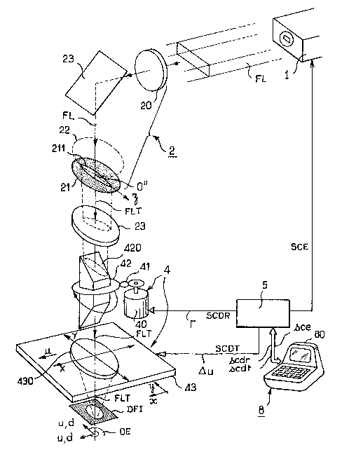
A rotating prism 420 is provided whereby
rotation o~ the prism in question through an angle ~
rotates the emergent light beam, i.e. the treatment
2S laser beam FLT, through an angle 2~.
Also, a second focussing lens 430 serving as an
objective lens is movable in translation in the
pre~iously mentioned directions OX and OY.
It will be understood that the embodiment of
the device in accordance with the invention shown in
figure 4a is particularly advantageous in that it
enables two methods to be used: in the first the
treatment Iaser beam FLT is scanned in rotation, the
focussing lens 430 being held in a fixed position and
centred on the optical axis OZ of the eye, of course,
~ 3 ~
26
the prism 420 then being rotated to obtain the
correspon~ing scanning of the treatment laser beam; in
the second method, with the prism 420 fixed in positionj
the treatment laser beam emerging from the prism 420 is
directed along the optical axis OZ of the eye and the
focussing lens 430 produces corresponding movement in
translation of the treatment laser beam FLT by
corresponding defocussing due to movement of the lens
430 in translation in direction X or in direction Y.
The rotator prism 420 may advantageously be a
Dove or Wollastom prism. Also, a diaphragm denoted DFI
may be provided between the lens 430 and the eye o the
patient to limit the luminous intensity received by the
eye OE oE the patient. It may be disposed in the
vicinity oE or on the eye. Of course, other direction-
changing mirrors can be provided on the path of the
laser beam FL to obtain an appropriate optical path to
enable unrestricted circulation of persons in the
environment of the apparatus and the practitioner.
The device in accordance with the invention in
figure 4a is particularly advantageous in that, over and
above any possible operation by;scanning the area oE the
eye to be treated in rotation, it also makes it possible
to carry out this operation by scanning the laser beam
over the area of the eye to be treated in translation,
in particular in the previously mention~ed two directions~
OX and OY. The lobe or lobes of the laser beam and the
beam direction Oz being oriented in the OY direction,
the scanning in one direction Ithe OX direction, for
example) is obtained by means of the rotator prism 420.
This orients the aforementioned direction Oz with the OX
direction foE subsequent movement of the treatment laser
beam FLT in the direction perpendicular to the new
orientation of the Oz axis, i.e. the direction OY. The
displacement in translation is effected by displacing
27
the lens 430 in the corresponding directions.
~ more detailled description of an object slit
211 profile specifically used in the case where
displacement in translation of the image of the object
slit 211 is brought about to carry out the treatment or
operation as aforementioned will be given with reference
to figures 4b, 4c, 4d.
Referring to figure 4b, the object slit 211 of
the diaphragm 21 and consequently the image of the lobe
or lobes of the treatment laser beam FLT for treatment
and correction by keratomileusis of myopia and
astigmatism has a substantially paraboIic profileO The
profile de~ined by one lip of the slit satisfies the
equation:
1 2
E~z) = 2 E (- - - ) (20)
max 2 2
R
It will be noted for convenience that the slit
211 has a longitudinal axis denoted O"x.
20In the above equation, the various parameters
are defined as follows:
E(z) represents the transverse dimension o the
object slit or of the lobe of the treatment laser beam
at the abscissa z on the longitudinal re~erence axis
25oriented relative to the sIit.~ The abscissa is
referenced relative to an origin point On.
Emax represents the maximal transverse
dimension of the object slit 211.
While carrying out the aforementioned operation/
30the practitioner is required to displace the image of
the object slit 211 in translation along a direction at
least perpendicular to the longitudinal axis O"z of the
object slit 211. Of course, the image of the object
slit 211 is then oriented in such a way that the
35longitudinal axis O"z of the latter is oriented in one
1 3 ~
28
of the directions OX or OY of figure 2a. Thus for a
direction u of orientation of the slit 211 or of its
longitudinal axis O"z in the direction oX or OY, the
equation relating the aperture of the slit E(u) and
the translation displacement increment denoted ~u,
this displacement being in the direction perpendicular
to the orientation direction u of the slit, is of the
form:
A 2
0 1 u
u a(e) 2 2 (21)
R
In this equation:
u represents the abscissa or position of the
edge of the slit on the longitudinal axis of reference
O"z, the slit itself being orien-ted in the direction u
corresponds to the direction OX or to the direction OY,
~ u represents the t~anslation displacement
increment in the direction orthogonal to the
aforementioned alignment direction u, i.e. ln the
direction OY or in the direction OX,
AUo represents the thickness of ablation or
correction at the centre of the area of the cornea to
be corrected at the time of displacement in translation
of the object slit 211 or of the lobe of the~treatment
laser beam in the direction OY or in the
direction OZ.
A description of an object slit 211 for
treatment and correction of the cornea by keratomileusis
for hypermetropia and hypermetropic astigmatism will
also be given with reference to figure ~c.
In the case of the aforementioned operation, the
object slit 211 and the corresponding lobe or lobes of
the treatment laser beam FLT have a substantially
parabolic profile satisfying the equation:
~ 3 ~ 3
29
E(z) = Emax ~- ~ (22)
As i.n figure 4b the orientation of the
longitudinal axis O"z o the object slit 211 in the
direction OX or in the direction OY serves to establish
the relationship defining the connection between the
displacement increment Qu in the direction perpendicular
to the orientation direction and the aperture E(u) of
the slit 211, this relationship being of the form:
u
E(u) = ~u 0 ~u ) (23)
a (e) 2
In the above equations (22) and (23), the same
notation designates the same parameters as :in the
previous equations (20) and:(21).
In an analagous manner~ to an operation carried
out by scanning the image of the object slit 211 in
rotation, in the case of scanning in translation the:
values of the displacement increment in the direction
perpendicular to the alignment direction of the axis O"z
of the object slit 211 and the irradiation times satisfy
similar equatlons.
Consequently, in the figure 4a embod~iment, the
device in accordance with the ~invention ~comprises
caIculation means denoted 8 for ~caIculating the
translation displacement increment ~u in the direction
OY or OX for an orientation u in the direction OX, OY,
the; increment for a given object slit satisfying the0 equation~
a(e)
~u = Emax u ~24)
In this equation the parameters a(e) and AUo
correspond of course to the deinitions given previously
in this _escription.
::
.
~31~3
Also, in the embodiment shown in figure 4a, the
device in accordance with the invention also comprises
means 8 for calculating the number of laser emission
pulses denoted NI2 and the number of translation
S displacements increments ~u in the direction OY, OX.
The number NI2 of pulses satisfies the equation:
2~ AUo (25)
NI = - - ND
2 ~u 2 a(e)
In this equation ND2 represents the number of
totally separate or adjacent images that can be formed
on the cornea.
In the same way as in the case of treatment or
correction by an cbject slit or object slit image
performing a rotating scan, in the figure 4a embod;ment
the calculation means 8 may also be used to calculate
the minimum total radiation time denoted T2min.
This satisfies the equation:
u
T = NI - = T(e) - (26)
2min 2 ND2 a(e)
In this equation, r(e) represents the minimum
time interval between two successive irradiations of the
same point on the cornea.
As will be noted from figures 3b, 3c, 3d, 3e,
4b, 4c and 4d in particular, the object slits 211,
whether used during an operation to effect scanning in
rotation or in translation of the area of the cornea to
be treated, are symmetrical with respect to their
longitudinal axis O'z or O"z. This corresponds to a
particularly advantageous, non-limiting embodiment in
which, without departing rom the scope of the present
invention, the slits may be asymmetrical with respect to
the longitudinal axis O'z or O"z provided that the
corresponding width of the slit at a given point z is
31
substantially the same~
As will be noted in figure ~c, in the case of an
object slit 211 used for treatment of hypermetropia by
scanning in translation the object slits, whether they
generate one or more lobes of the treatment laser beam
FLT scanned in rotation or in translation, may
advantageously comprise a curvilinear shape edge denoted
C at the end. This edge at the end is, as shown to a
larger scale in figure 4c, symmetrical with respect to
the longitudinal axis O"z. The curvilinear shape
departs from the variation law p = constant,
representing a circular arc in polar coordinates, to
eliminate edge effects from the resulting profile of the
total ablation obtained.
As will be noted in figure 4c, in a non-limiting
way r the curvilinear shape C may be concave and convex
with a point of inflection. Likewise, provided that
the curvilinear shape C departs from the variation law
p = constant, the edge at the end may equally well be
continuously concave, as shown in dashed outline in the
enlarged view of figure ~c.
A curvilinear character of this kind for the
edge of the slits at the end improves the continuity of
the curvature in transitions between corrected and
uncorrected areas. Thus any slit of which an edge at
the end has a non-zero width or aperture;could comprise
the aforementioned curvilinear slit C. The curvilinear
shape C, in the absence of any point of inflection,
provides for transitions between corrected and
uncorrected areas at which there is a discontinuity in
the curvature.
Of course, in an analagous way to the embodiment
of the object slits in figure 3e in the case of
rotational scanning for a plurality of object slits 211
on the same diaphragm 21, in the case of treatment by
32 131~3
scanning in translation it is also possible to use a
plurality o~ object slits 211 on the same diaphragm~ A
diaphragm of this kind is shown in figure 4d, in which
three slits 2111, 2112 and 2113 have been shown by
way of non-limiting example. The various object slits
are spaced in a direction perpendicular to their
longitudinal axis O"z by a distance at Ieast equal to
the widest aperture EmaX thereof.
A prototype of the device in accordance with the
invention was manufactured with the object slits 211 as
described previously with reference to figures 3b, 3c,
3d, 4b, 4c and 4d.
To give a non-limiting example, in the case o~
an object slit such as that shown in figu~re 3b, the
object slit 211 had a length substantially equal to 3.2
mm, its length being measured along the longitudinal
axis olz~ and a width or maximal dimension in the
direction perpendicular to the aforementioned
longitudinal axis substantially equal to 0.8 mm.
An object slit 211 as shown in figure 3c had a
length substantially equal to 3.2 mm and a maximal width
in the order of 1.4 mm.
In the case of an object slit 211 as shown in
figure 4b the length of the slit along the longitudinal
axis O"z was in the order of 6 mm and its maximal width
in the order of 1 mm.
Of course, the foregoing dimensions of the
object slits 211 are given by way o non-limiting
example only, since it is to be understood that these
dimensions vary according to the total magnification of
the optical system of the device in accordance with the
invention. The latter may of course and advantageously
be provided with an optical system offering variable
magnification so that from a particular design of object
slit the practitioner is in a position to choose the
9 ~ ~
33
final dimension of the image of the lobe or lobes of the
treatment laser beam FLT given by the aforementioned
object slits.
In accordance with another advantageous
characteristic of the device in accordance with the
invention, with particular reference to the figure 4a
embodiment in which the diaphragm 21 is fixed, each slit
may advantageously have a variable profile to provide
for compensation for any irregular distribution of the
light energy over the cross-section of a lobe of the
treatment laser beam FLT.
~ s will be noted in figure 4e, the variable slit
211 may comprise at least one edge made up of mobile
strips denoted 2110, these strips being movable in
lS translation in a direction perpendicular to the
longitudinal axis O"z of the slit. The mobile strips
2110 may of course be disposed to slide relative to each
other, each being adapted to be driven by the
intermediary of a motor or like means 2111. It will be
understood of course that in the case of the figure 4e
embodiment the dimensions of the object slit 211 may be
increased to facilitate implementation of the movable
strips, the magnification of the optical system of the
device in accordance with the invention being~adjusted
~5 accordingly.
One example of an operation for treatment of
myopic astigmatism by keratomileusis using the device in
accordance with the invention shown in figure 4a and
scanning of the area to be treated in translation will
now be described with reference to figure 5a.
The total resulting ablation is in this instance
obtained by means of a slit such as that shown in figure
4d, for example, the image of the slit or the lobe of
the treatment laser beam FLT being displaced in a
direction perpendicular to the longitudinal axis O"z in
`3
34
consecutive elementary increments. The elementary
displacement increments being equal, the effect of the
treatment is to produce a channel of uniform parabolic
profile. The length of the channel is of course equal
to the distance over which the slit is displaced and its
width is equal to the length of the slit.
In a particularly advantageous method of
working, two operations are effected along two
perpendicular axes to achieve complete correction of the
cornea COR.
In the case of myopia, this method of working
has the following advantages:
- it eliminates the problem of precisely
focussing the end or the image of the slit on the
rotation axis in the case of scanning in rotation, and
- it enables all types of astigmatism to be
corrected.
The longitudinal axis O"z of the slit being
oriented in the direction OX, for example,.in figure 2a,
irradiation of the object slit 211 in successive
positions spac0d by a constant translation increment ~Y
in the direction OY in figure 2a within a range of
displacement ranging between -R/ ~ and +R/ ~ serves to
obtain with respect to the axis OX an ablation~ profile
B(X) defined by the equation:
B(X) = a(e) ~ X~ [ _ ~ _ ] (27)
LQ Y~ ~ ~
In this equation:
- E(X) represents, of course, the profile of
the slit ~at the abscissa X and ~xy represents
the constant translation displacement increment in
the direction Y, the slit being oriented in the
direction X,
- R is the radius of the area to be corrected
3s ~31~3
centered at O".
As previously mentioned in this description,
when the axes OX and OY from figure 2a correspond to the
principal directions of the meridians corresponding to
the ends of the curves at the centre of the cornea, the
principal astigmatism directions, the ablation profile
to be obtained is expressed by the equation
X y 1 Y
A(XlY) = A 0(_ _ ) o - (28)
2 2
2 R 2 R
In equation ~28) the parameters AXo and
AYo satisfies the equations:
x R
A = ( - ) (29)
O -- --
2 r r
x
y R
A 0 = ( _ - _ ) t30) :
2r r
Y
The ablation function may be regarded as the
result of summing two ablation functions, one a function
of X only and the other a func~ion of Y only. In
equations (29) and (30)l rx represents the radius of
curvature of the cornea in the direction OX and r
represents the radius of curvature in the direction OY,
r representing the radius of curvature of the cornea in
a meridian direction at: the a2imuth angle ~ previously
mentioned.
Adopting the following notation:
A + A
O O
2 (31)
.
~ 3 ~ 3
36
~0
X ¦ (32)
l AX
O
~
R = R ¦ (33)
I ~Y
O
the equation for the resulting total ablation function
may be written:
x2 2
A(X,Y) = A (l - _ - ) (34)
R2 R2
x y
The iso-ablation curves are thexefore ellipses in the
general case and the equation for the ellipse which
delimits the ablation contour is:
2 y2
+ = 1 (35)
2 2
R R
x y :
As shown in figure 5a, theory indicates that
the resultant ablation should extend from -RX to +RX
on the OX axis and from -Ry to +Ry on the OY axis.
The ablation profile is thus contained within two
orthogonal rectangles with respective lengths 2RX
and 2Ry and the same width R ~ and whose common area
is square inscribed in the circle Ce of radius R centered
at O. The ablation profile obtained is perfect within the
square where they intersect although a satisfactory approx-
imation of the ablatlon profile is nevertheless obtained
outside the square in the areas peripheral
i31~3
37
to the latter, the areas FGHI in figure 5a, the central
area consisting of the square being denoted A.
In the case of pure myopia with no astigmatism,
r = ry and Ao = A 0 = A 0.
Thus correction or treatment by means of an
object slit scanned in translation along two orthogonal
directions produces an optimal effect where the areas
scanned by the treatment laser beam FLT in the
aforementioned directions intersect, that is over a
square in plane projection.
To extend this action beyond the intersection
square and to obtain satisfactory correction over a
substantialy circular area it is possihle to extend the
lateral scanning of the treatment laser beam FLT while
modulating the displacement increment ~u between two
adjacent positions, the aforementioned increment ~u
remaining constant in the intersection area, of
course.
It has been shown that the ablation profile in
the first area made up of the three areas A, F and H
(that is for -R/y~ ~ X ~ ~R/~ ) is achieved by
irradiating a slit parallel to the axis OX and moving by
increments QYX in the direction perpendicular to the
OY axis. ~ ::
Likewise, the ablation profile in the area made :
up of the areas Ir A and G ~that is for R/~r2 ~ Y
R/v~) is achieved by irradiating a slit parallel to the
OY axis moved in increments ~YX or ~u along the OX
axis.
This second operation, correction of the profile
along OY, does not modify the profile along an axis
parallel to ~X, but deepens it uniformly ~Y = constant)
in particular by an amount AYo over all of the axis
OX, that is for Y = 0.
To complete the resulting total ablation profile
38 ~31~9~
along OX and to avoid any discontinuity for X = ~R/~
the scanning in translation along OX of the slit
which generates the ablation profile along OY can be
extended beyond these values, with the translation
displacement increment along oX increasing wlth X for
¦X ¦ > R/~ -
The device in accordance with the invention as
shown in figure 4a uses the calculation means 8 to
determine the value of the linear displacement
increment denoted ~Yx~ for example to obtain an
exact extension of the parabolic profile for Y = 0,
the translation displacement increment for a
corresponding ablation function satisfying the
equation:
A(X,0) ~ Ao( _ ) : (36)
x
The transIation displacement increment then :
satisfies over all of the treatment domain comprising
areas F, A and H in figure Sa the equation:
E _ , for _ ~¦X ~S R ~ :
1 2~ ~ ~ (37)
Y O
(X) = R2
x
E 2 a~e) for ¦X ¦~ _ :
AY ~
o
In equations (36) and (37)l RX defines the
total irradiation domain in the X direction.
The resulting total ablation function Ax(X,Y)
which defines the resulting total ablation in rectangles
F and H in figure 5a, that is to say for
~ 3 ~ 3
39
_ ~ IX I ~ RXl IY
satisfies the equation:
E(Y)
A (X,Y) = a(e) (38)
~ X
In this equation E(Y) represents, of course, the
profile of the slit used, the slit having its
longitudinal axis O"z oriented in the Y direction and
aYX corresponding to the values of equation (37) for
the values of X included in the areas F and H..
The working method previously described with a
slit procuring scanning or the treatment laser beam FLT
in translation or using a slit with a parabolic profile
as explained previously in this description thus yields
an ablation profile which over the periphery of the area
of an ellipse denoted E in figure 5a, with half-axes
Rx and Ry~ contains eight "perfect" points by~ which
is meant points of zero ablation.
O course, in the case where there is a
requirement not to irradiate the cornea COR beyond an
area of radius R it is possible to mask the latter with
a mask comprising a circular hole of radlus R.
There are shown in figures 5b and 5c
respectively a profile characteristic of keratomileusis
ablation for myopia with no astigmatism and a profile
characteristic of keratomileusis ablation for
30~ hype:rmetropia.
In figures 5b and 5c the units have not been
marked on the coordinate axes. In the case of an
operation by keratomileusis on myopia, an ablation
corresponding to a correction of 15 diopters has a depth
of 0.15 mm and extends over an area 5 mm in diameterO
.
~3~ ~9~3
The initial radius of curvature is increased to 10.6 mm.
In the case o figure Sc, in which the units
have not been shown on the coordinate axes, an ablation
corresponding to a correction of 15 diopters has a depth
of 0.15 mm and extends over an area 9 mm in diameter.
The initial radius of curvature of 7.8 mm is reduced to
5 mm.
The device in accordance with the invention
makes it possible to overcome the limitations of prior
art devices through the use o an illumination and
treatment laser beam the specific shape and displacement
of which are computed so that their combination produces
the required ablation shape.
When the slit or slits is or are irradiated by a
particular pulse from the laser the image of the slit(s)
projected onto the cornea COR is, so to speak, etched on
to the surface and causes by photodecomposition the
elementary ablation in question. The sum of these
elementary ablations distribut.ed over the cornea in
accordance with the mathematical laws prevlously
established produces the re~uired modification to the
shape o the corneaO
Unlike the prior art devices, in which the
concepts of illumination time were involved, the
concepts of the laser pulse frequency and of the speed
of displacement of the object slit ~or its image) are
replaced by the concepts of linear or angular
increments, as appropriate, between two adjacent
positions of the image or of the lobe of the treatment
laser beam. Here "adjacent'~ is to be understood in the
geometrical rather the temporal sense. In other words,
the fact that two geometrically adjacent, that is to say
geometrically consecutive, elementary ablations are
temporally consecutive is not relevant. Generally
speaking, they are not.
.
41 13~9~3
All the considerations previously mentioned
combined with the concept of a threshold relating to
each elementary ablation serves through summation of the
elementary ablations in question to obtain a corrected
or treated surface that is particularly satisfactory and
the degree of roughness of which is substantially less
than 1 ~m.
In the case of rotational scanning, there is
generally projected onto the eye OE a beam whose
transverse cross-section is caused to rotate about the
projection axis O, which is of course substantially
coincident with the optical axis of the eye to be
treated. The cross-section of the treatment laser beam
FLT is of elongate shape, of course, and in a
particularly advantageous way has at least one or
several lobes as defined previously. The generatrix at
the end of the treatment laser beam or the corresponding
Iobe coincides with the rotation axis O in figure 2a.
The ablation is done by applying the beam to a large
number of successive angular positions, spaced by the
appropriate angular increment o~ rotation about the axis
O. To obtain the required correction the cross-section
of the treatment laser beam FLT,~ the energy density~per
unit surface area of which is substantially constant,
~5 has the profile as de~ined pre~viously on the basis of
the object slits 211.
In the second embodiment, in particular using
the device as shown in figure 4a, the resulting total
ablation is obtained by scanning the treatment laser
beam FLT in translation by successive linear increments.
The displacement takes place in the direction
perpendicular to the longitudinal dimension of the
largest dimension of the lobe of the laser beam~FLT and
perpendicular to the optical axis O of the eye OE.
Several operations are needed to carry out a complete
' ' ` ' ~ ~ '`
.
42 13~ 3
treatment.
Of course, and in a non-limiting way, it is
possible to carry out several operations, for example,
the treatment laser beam FLT undergoing after each pass
a rotation of a fraction of a circle about the optical
axis O. After n passes (n/2 if the beam is
symmetrical), the combination of the aforementioned
operations produces an nth order circular symmetry abla-
tion more or less approximating the required effect.
A particularly advantageous instance, as
previously described, is the use of a beam of parabolic
cross-section the lobes of which have a parabolic shape
as described previously, the laser beam being scanned in
two passes along two perpendicular directions.
Compared with rotational scanning of the
treatment laser beam FLT, scanning in translation for
correction of myopia avoids a problem specific to rotary
scanned beams, namely that the centre of the eye where
the ablation is strongest coincides with the centre of
rotation and that the latter is situatèd by design at an
end of the impact area. In the event of any error in
aligning this impact area with respect to the rotation
axis, total absence of ablation (or its opposite,
excessive ablation) may result in the immediate vicinity
of the centre of the eornea. This problem is absent in
the case of beams scanned in translation.
Furthermore, in the case of scanni~ng in
translation the choice of this scanning mode (along two
orthogonal directions) provides a simple means of
correcting astigmatism. For this, it is sufficient for
the two orientations of the beam along the directions OX
and OY to coincide with the principal directions of
astigmatism. It then suffices to change the average
density of exposure by changing the length of the linear
increments between the two orthogonal passes to obtain
~3
an ablation of elliptical rather than circular
symmetry.
The translational scanning treatment laser beams
may of course be used in various ways, the bearns with
different orientations being applied either successively
or simultaneously.
Another particularly advantageous embodiment of
an object slit 211 and a diaphragm 21 will be described
with reference to figures 6a through 6d.
Referring to figure 6a and figure 6b, the object
slits as previously shown in figures 3b, 3c,~3d, 3e, 3f,
4b, 4c and 4d may advantageously be formed on a
diaphragm 21 with a curved surface matching the surfaoe
of the cornea COR. This embodiment improves the quality
of focussing of the image of the object slit on the
cornea COR. In the case of figure 6at the curved
surface forming the diaphragm 2l is a spherical dome and
the diaphragm may be rotated about its axis of symmetsy,
as previously described. In the case of object slits
scanned in translation, the curved surface forming the
diaphragm 21 may advantageously, and as shown in figure
6b, be a semicylindrical surface the longitudinal axis
of which is oriented in the translation direction d, the
object slits having their axis O"z perpendicular~to~ the
longitudinal axis of the aformentioned half-cylinder.
A particularly advantageous embodiment of the
diaphragm 21 will be described with refèrence to figures
6c, 6d and 6e. ~
In the aforementloned figure 6c the diaphragm 21
comprises a semicylindrical surface of radius R with a~
longitudinal axis O'''x. The semi-cylindrical surface
has an object slit 211 with an aperture or width in the
direction O'''x denoted E(~). The aperture is, for
example, symmetrical to a plane P orthogonal to the
longitudinal axis O'''x, this plane containing the
~3i~
44
directions O'''y and O'''z orthogonal to the direction
of the longitudinal axis O'''x. In figure 6c, S
represents the middle of the aperture or the width of
the slit at a height z corresponding to a given angle ~,
the angle ~ being defined as the angle between the
radius vector O'''S of a point S on the geometrical
locus LS, the curve of symmetry of the object slit 211,
and the direction 0y. The width E(~) of the object slit
211 satisfies the equation.
E(~) = E (~) sin3~ (39)
In this equation, E(~/2) represents the maximum
width or aperture of the object slit 211 for ~ = ~/2.
lS It will of course be noted, as will be described
in more detail later, that in the case of an operation
by keratomileusis to cure myopic astigmatism the radius
R of the semicylindrical surface constituting the
diaphragm 21 determines the area within which the prac-
titioner operates on the cornea COR. To give a non-
limiting example, the aforementioned radius is taken as
equal to the operating area, the magnification of the
Eocussing optics being taken as equal to unity. It is
obvious that any semicylindrical diaphragm of appropria-
tely similar shape could be used, the magnification ofthe focussing optics being adapted accordingly.
To correct the cornea COR by keratomileusis for
myopic astigmatism, for example, the diaphragm 21 as
shown in figure 6c is disposed relative to the cornea
COR so that its concave side faces towards the area of
the latter to be treated. The cornea COR is assumed to
have a circular surface of radius R' and the object slit
211 as shown in figure 6c is illuminated by the laser
beam FL. The longitudinal axis O'''x and the transverse
3S axis P' "y of the diaphragm are oriented in the
1 3~ ~9~
principal directions of astigmatism OX, OY of the cornea
COR, these principal directions havlng been determined
beforehand by the practitioner.
The device in accordance with the invention
further comprises drive means ~00 for rotating the
diaphragm 21 about the axis O " 'y, the rotation drive
means 400 advantageously comprising a stepper motor and
two rotation half-shafts 401, 402 driven by the latter.
As will be noted on observing figures 6c, 6d and
6e, the width E(~) of the object slit 211 which is also
shown in figure 6c by the intersection of the slit and a
plane Q for which the equation is Y = R Cos~, is
projected on the axis OX as an image of width E (a, ~)
when the slit 211 is illuminated with parallel light,
for example. The width of the slit projected on the
axis OX satisfies the equation:
E'(~,~) = E(~). sin ~ (40)
In this equation, ~ represents the angle of
inclination by which the diaphragm 21 is rotated and in
particular of the axis O'''z thereof relative to the
direction OX. The slit 211 t:urns substantially on a
sphere with the same radius as the cylinder and, as the
diaphragm 21 is rotated, any middle point S at a height
z corresponding to a given angle ~ performs a circle CS
in the aforementioned plane Q, as shown in figures 6c
and 6e.
If it is assumed that the ablation function
A(~,~) corresponds to the ablation function A(X,Y)
deined by equation (34) and is proportional to the
number of pulses received for an elementary displacement
less than E'(~,~? and therefore less than the width
E'(~,~) of the image of the slit on the axis OX divided
by the elementary displacement Qx(~) (along the OX axis)
for each laser pulse, we may write:
~ 3 ~ 3
~6
X(a)=Rsin~Cosa and X~ d~ Rsin~ Cosada = - Rsin~ Sin~ da
and QX(a) = R sin ~ sina~a
whence
E'(~
A(X,Y) = A(~,~
~X(~ )
that is
(E)~ t41)
R Sin~a
Given the chosen ablation function A(X,Y) ~:~
defined by equation (34) above, OX and OY are chosen
such that Rx ~ Ry and R is chosen such that R = Ry as
shown in figures 6d and 6e in particular.
Using the same notation~ as previously, the~
ablation function may be written:
2 2
A0 X Y
A(X,Y) ~ ) t42)
2 2 2
Rx
Given the equations: :
~ X = R sin~ cos a
: Y = R cos~ : : ::
the ablation function becomes:
A0 R 2 2
AtX,Y) = Ata,~ tl - cos a) sin ~ t43)
Rx
Given equations (41) and t43) above, the
ablation function may be related :to the law of the
aperture of ~he slit Et~) and the rotation increment ~a
by the equation:
;
47 131~3
Et~) RAO 3 Rx 2
= . sin ~ cos ~) (44)
2 2
Rx
It then suffices to choose:
E(~) = E (~) sin
and
0(1 _ R 2 -1
Rx
Choosing E(~/2) and Q 0 for a given
semicylindrical diaphragm produces the required
profile.
By modulating the angular rotation increment ~
the previously described embodiment can correct
astigmatism of the cornea and myopia~ without any
problems of edge discontinuities at the periphery of the
correction area or excessive ablation at the centre of
the cornea. The junction between the corrected area and
the uncorrected area is perfect. Also, in the absence
of any astigmatism the previous equations hold, ~;given
that Rx = Ry = R. In all cases, the X and Y ablation
functions depend only on ~ and ~ respectively.
To facilitate use of the device in accordance
with the invention as shown in figure 3a or in figure 4a
the calculation means 8 ma~y comprise a mic~rocomputer 80
with its peripheral devices. The memory areas of~the
microcomputer store programs and/or subroutines for
calculating the numbers of laser pulses NIl, NI2
previously ~entioned in the description, the total
irradiation times Tlmin' T2min~ and
sub-routines for sequencing and synchronising the
displacement of the treatment laser beam FLT. These
131 ~43
~8
sequencing programs are used, for example, to generate
rotation or translation displacement commands scdr and
scdt and laser emission commands sce. The program or
subroutine can also include a program for modulating
the rotation increment r as a function of the azimuth
angle ~ or the translation increment ~u as a function
of the value of the X or Y ascissa of the rotation
increment a a .
To facilitate the work of the practitioner the
microcomputer 80 may further comprise in its memory area
a "menu" type program inviting the practitioner, through
an interactive type dialogue, to define at least the
principal directions of astigmatism of the eyeball
relative to a reference marker, the principal directions
having been established by the practitioner as a result
of a diagnosis.
The "menu" program may advantageously also
invite the practitioner to specify the value of the
parameter R defining the optical area for operation and
correction of the cornea COR. It may also invite the
practitioner to designate the treatment methad i.e.
scanning the object slits or images of the object~slits
in rotation or in translation. Finally, the type of
operation may be specified according to the particular
case under treatment.
The microcomputer 80 can of course be connected
by a BUS type link to the means 5 for synchronising the
displacement of the image of the lobe or lobes o~ the
treatment laser beam FLT. The means 5 for synchronising
the displacement of the image may advantageously
comprise an input/output interface circuit generating
from rotation or translation displacement commands scdr
and scdt and emission commands sce respective commands
SCDR, SCDT, SCE for the displacement control means 4 and
the laser emission means l. The input/output interface
49 13i4~3
circuit will not be described in detail, as it may be
provided by any conventional type interface with
provision for controlling the stepper motor in
particular.
Finally, to facilitate the work of the
practitioner, following his diagnosis, the device in
accordance with the invention may comprise a set of
diaphragms each comprising an object slit 211 as defined
and described with reference to figures 3b, 3c, 3d, 3e,
3f, 4b, 4c, 4d, 4e, 6a, 6b, and 6c.
There has thus been described a device for
performing surgery on the cornea in which rotational or
translational scanning of a laser beam having at least
one lobe of elongate cross-section produces a precise
law of ablation over the area of the cornea COR of the
eye to be corrected. Laboratory tests have shown that,
compared with prior art devices in which the depth of
ablation was controlled by the time of exposure to the
treatment laser beam, the corrected surfaces~ after
treatment, that is to say the surfaces of the cornea
serving as the input optical surface of the eye of the
patientj show a much reduced degree o~ roughness~ thus
conferring superior optical qualities on the surfaces of
the treated cornea. It has been observed that;the
degree of roughness of the surfaces after treatment;does~
not exceed 1 ~m. The degree of roughness of the corneal
surfaces after treatment with the prior art devices may
be explained by the ~act that these devices have the
disadvantage of applying the laser emission power
simultaneously to the major part of the cornea, the
effect of which is to create an acoustic shock wave
resulting from simultaneous vapourising of material over
the anterior surface of the cornea. This kind of
phenomenon can also have unwanted physiological
consequences, such as ejection of endothelium cells,
so 131~9~3
for example. The device in accordance with the
invention makes it possible to eliminate the
disadvantages of these devices since the resulting total
ablation when the device in accordance with the
invention is used results from the summation of
elementary ablations distributed over the cornea
according to precise mathematical laws, each elementary
ablation being carried out with minimal energy density.
Of course, the device in accordance with the
invention is not limited to refractive eye surgery. It
may also constitute a device for shaping or correcting
the shape of an object by laser treatment of the surface
of the object. In this case, the device comprises the
means 2 for generating a treatment laser beam FLT
comprising at least one lobe Ll ... L6 of elongate
cross-section and means 3 for focussing the image of the
lobe or lobes of the treatment laser beam FLT onto the
area of the object OE to be corrected. The means 4 for
moving the image of the lobe or lobes of the treatment
laser beam FLT over the area of the object to be
corrected serve to move the latter over the area of the
object to be corrected. The means 5 for synchronising
movement of the image of the lobe or lobes of the
treatment laser beam FLT over the area of the object OE
to be corrected with the treatment laser beam pulses
serve to perform the correction or shaping by summing a
plurality of elementary discrete ablations. As shown in
figure 7, the image of the lobe or lobes of the laser
beam is focussed in such a way that the generatrix of
one end of the lobe or lobes or the longitudinal axis of
symmetry of a lobe or the lobes of the laser beam FLT is
coincident with the axis of symmetry OZ of the object to
be treated or of an elementary surface of the object to
be treated. The means 4 for moving the image of the
lobe or lobes of the treatment laser beam FLT over the
9 ~ 3
51
area of the object to be corrected serve to move the
image of the lobe or lobes Ll ,.. L6 of the laser beam
in rotation about the end generatrix or the longitudinal
axis of symmetry of the lobes of the treatment laser
beam FLT. The rota-tion is applied in rotation angle
increments. The device corresponds substantially to the
embodiment of figure 3a.
Furthermore, in an embodiment corresponding to
that of figure 4a of a device for shaping or correcting
the shape of an object by laser treatment, the means 4
for moving the image of the lobe or lobes of the
treatment laser beam FLT over the area of the object to
be treated provide for movement in translation in a
direction d substantially perpendicular to the largest
dimension 0z of the lobe of the treatment laser beam
FLT. The movement in translation may be e~fected in
displacement increments ~u, the movement in translation
being defined by u = X or u = Y defining a plane
tangential to the surface of the object OE at the point
0 on the axis of symmetry of the object or an elementary
area of the latter to be treated.
A non-limiting alternative embodiment of the
device in accordance with the invention for shaping or
correcting the shape of an object or for performing
refractive eye surgery will be described with reference
to figure 7, this embodiment being based on the
embodiment of figure 3a or figure 4a.~ Referring to
figure 7, the device in accordance with the invention
further comprises a real time shape recognition system
comprising at least two video cameras 1001, 1002 viewing
the object or the eye OE to be treated and transmitting
image data to the calculation means 8. The video
cameras 1001, 1002 allow for monitoring the progress of
the shaping or correction of the object during the
treatment process. The shape recognition means may
~ 3 ~
52
comprise shape recognition means available through
normal trade channels and will not be described in
detail.
As shown in figure 7, a series oE mirrors Ml,
M2, M3, M4 deflect the treatment laser beam FLT. At
least one of these mirrors, the mirror M4, is mounted on
a gimbal 2000. The two frames of the gimbal mounting
are shown in cross-section in figure 7 to avoid over-
complicating the drawing. Drive and orientation
adjustment means for the adjustment mirror comprise DC
or stepper motors, for example. These motors are
controlled by the shape recognition means 1001, 1002
through the intermediary of the calculating means 8,
using a bus type link~ The shape recognition system
therefore serves to monitor the progress of the
correction or treatment during the process and to
control the deflection of the treatment laser beam FLT
by means of the mirror M4 in the event of uncontrolled
movement of the object or of the eye of the patient. In~
the latter case the practitioner can advantageously make
coloured marks on the cornea of the patient before the
treatment begins, using methylene blue, for example.
Note, however, that if an arrangement o~ this kind is
used with the device in accordance with the invention as
shown in figure ~a, the shape recognition means 1001,
1002 can control the focussing lens 430 directly by
means of an X-~ movable table 43.
The device ln accordance with the invention is
thereore usable Eor shaping or correcting the shape of
mechanical objects such as contact lenses or
intra-ocular implants and for refractive eye surgery.
: