Sélection de la langue

Search

Sommaire du brevet 1315312 

Énoncé de désistement de responsabilité concernant l'information provenant de tiers

Une partie des informations de ce site Web a été fournie par des sources externes. Le gouvernement du Canada n'assume aucune responsabilité concernant la précision, l'actualité ou la fiabilité des informations fournies par les sources externes. Les utilisateurs qui désirent employer cette information devraient consulter directement la source des informations. Le contenu fourni par les sources externes n'est pas assujetti aux exigences sur les langues officielles, la protection des renseignements personnels et l'accessibilité.

Disponibilité de l'Abrégé et des Revendications

L'apparition de différences dans le texte et l'image des Revendications et de l'Abrégé dépend du moment auquel le document est publié. Les textes des Revendications et de l'Abrégé sont affichés :

  • lorsque la demande peut être examinée par le public;
  • lorsque le brevet est émis (délivrance).
(12) Brevet: (11) CA 1315312
(21) Numéro de la demande: 1315312
(54) Titre français: CHARIOT
(54) Titre anglais: LOAD TRANSPORTING DOLLY
Statut: Durée expirée - après l'octroi
Données bibliographiques
Abrégés

Abrégé anglais


ABSTRACT OF THE DISCLOSURE
A load transporting dolly for moving heavy articles is
shown. The dolly particularly facilitates the moving of heavy
articles up or down a flight of stairs or steps. It also provides
protection to the article as well as the steps from scretches and
similar accidental damages and it provides suitable hand-holds
for carrying the article up or down steps or stairs.

Revendications

Note : Les revendications sont présentées dans la langue officielle dans laquelle elles ont été soumises.


The embodiments of the invention in which an exclusive
property or privilege is claimed are defined as follows:
1. A load transporting device comprising
a generally L-shaped body having a platform member and a
heel portion disposed at a rear edge therein and extending
upwardly and substantially vertically relative to a top surface
of said platform member,
a durable resilient material covering over said top surface
of said platform member and over said heel portion,
two caster means disposed at the underside of said platform
member and located at two corners of a front edge therein
opposite to said rear edge,
two additional caster means disposed at the underside of
said platform member and located at a selected short distance
from said rear edge,
at least one tilt handle means secured to the underside of
said platform member and located immediately adjacent to said
front edge,
at least two lift handle means secured to the underside of
said platform member and located at a selected location between
said front edge and said rear edge,
a pair of elongated strap means secured to said platform
member and extending outwards from said rear edge therein,
at least one additional elongated strap means secured to
said platform member and extending outwardly from said front
edge.
2. A load transporting device according to Claim 1 including
at least one additional lift handle means secured to said
underside of said platform member and located in the proximity of
said two additional caster means.
3. A load transporting device according to Claim 2 wherein said

resilient material is a woven fabric material.
4. A load transporting device according to Claim 3 wherein said
strap means are made of nylon webbing material.
5. A load transporting device according to Claim 4 wherein said
pair of elongated strap means is a double layer strap means being
sewn together at at least two locations along its length therein
to form loop means on said strap means.
6. A load transporting device according Claim 4 wherein said
additional strap means is a double layer strap means being sewn
together at at least one location to provide at least one loop
means therein.
7. A load transporting device according to Claim 1, 5 or 6
wherein said two caster means and two additional caster means are
of ball bearing type rotatable with respect to vertical axes
perpendicular to the plane of said platform member.

Description

Note : Les descriptions sont présentées dans la langue officielle dans laquelle elles ont été soumises.

1315312
The present invention relates to a load transporting
device for moving heavy objects or appliances and
particularly to a wheeled dolly operative to facilitate the
moving of heavy articles on ground surfaces as well as up or
down a flight of stairs or steps.
In moving large heavy objects or articles such as a
refrigerator or chest of drawers or a desk, one diffiulty is
to move such heavy articles up or down steps or a flight of
stairs. The physical form or shape of such articles is such
that there is often no available hand-holds to exercise the
moving. The problem is worsen in that in order to protect
the article from accidental damages it is usually necesary
to wrap the article with protective blankets which further
eliminates the available hand-holds for lifting and moving
~he artcle up or down flights of steps or stairs.
The general object of the present invention is to
pro~vide a simple, sturdy and inexpensive hand dolly which
is operative for moving heavy and bulky articles with
relative ease both on ground surfaces and up or down flights
of steps or stairs.
Another object of the present invention is to provide
a transpor-t device which protects the article being moved as
well as the surface of the floor or steps on which the
article is being transported from being scratched by the
dolly.
Yet another object of the present invention is to
provide a hand dolly which lends a positive support to the
article being transported as well as provides various
convenient hand-holds to enhance the moving of the latter
up or down flights of steps or stairs.
Yet a further object of the present invention is to

1 3 1 53 ~ 2
provide a hand dolly which facilitates the tipping of the
heavy and bulky article Eor moving it up or down flights of
steps or s~airs and which includes means for maintaining the
article stably during moving.
These and other objects of this invention together with
its advantages will be more apparent from the following
description and drawings which illustrate a specific embodi-
ment by way of example and in which:
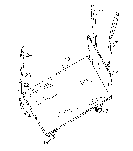
Figure 1 is a front perspective elevation view showing
the hancl dolly according to the present invention.
Figure 2 is a bottom perspective elevation view
thereof.
Figure 3 is a side elevation view thereofO
Figure 4 is a perspective side view showing the use of
the hand dolly of the present invention for moving a large
article up or down a flight of steps.
Referring now to the drawings in which like reference
numerals designate corresponding parts in the several views,
the hand dolly 10 has a generally ~ectangular platform body
11 and an upstanding vertical heel portion 12 located at one
end so that the hand dolly 10 is generally L-shaped. The~top
surface of the platform body 11 as well as the front and
back surfaces of the heel portion 12 are fully covered with
a durable protective resilient material 13 such as a carpet
; 25 made of woven fabric material or other durable sheet
material. Two front casters 14 and 15 are respectively
provided at the underside of the platform body ll at the
corners of a front edge therein opposite to the heel portion
12. Two rear casters 16 and 17 are provided at the underside
of the nlatform body 11 and are located at a selected short
distance from the rear edge at which the heel portion 12 is

1315312
located. The casters 14 through 17 are preferably of heavy
duty ball bearing type that are also rotatable with respect
to their vertical axes perpendicular to the plane of the
platform body. A tilt handle 18 is provided at the underside
of the platform body and are located adjacent to the front edge
therein. A pair of lift handles 19 and 20 are provided at a
short distance from the tilt handle 18 and are located at
approximately the mid point between the front edge and the
rear edge of the platform body 11. An additional lift handle
21 is provided at about the mid point between the rear casters
16 and 17. An elongated loop type towing strap 22 made of
strong webbing material such as nylon is provided at the front
end of the platform body 11. The strap 22 may be sewn together
at at least one point 23 at a short distance from the free end
therein to provide a smaller loop 24 to facilitate a tight
grip on the strap 22 for towing the dolly by wrapping -the
smaller loop 24 around the wrist of the mov~er. Two loop type
suppor-ting straps 25 and 26 are provided at the heel end of
the dolly. The supp~orting straps 25 and 26 are also made of
the same strong webbing material and may be sewn together at
at least two evenly spaced points 27, 28 and 29, 30 respective-
ly on each strap to provide selective tight gripping loops
therein. The heel portion 12 may be reinforced by right angle
members secured at the right angle edge between the heel
portion and the platform body 11.
The hand dolly 10 according to the present invention
may be used to move a heavy bulky article on ground surface
by placing the article on the platform body 11 and towing
it along the ground with the towing strap 22. The smaller
loop 24 on the strap 22 can be wrapped around the wrist of
the mover to provide a positive tight grip on the strap.

1 3 1 53 1 2
Alternatively, the supporting straps 25 and 26 may be used
to tow the dolly along the ground; however, preEerably the
towing strap 22 normally should be used for towing such that
the rear of the article abuts the heel portion 12 to prevent
the artcle from sliding off the platform body 11 due to
inertia~
As shown in Figure 4 when it is necessary to move the
bulky article up or down a flight of steps or stairs, the
hand dolly with the article resting thereon is first
positioned with the heel portion located a short distance
from the steps. One person would -then stand at a selected
number of steps above the ground and gripping the supporting
straps 25 and 26 on his hands by wrapping a selected loop
of the straps on the wrists. A second person would then
reach down to grip the tilt handle 18 underneath the front
edge of the platform body to lift and tilt the front end of
the hand dolly lO upwards such that the article is tilted at
an angle towards the steps to rest on the heel portion 12 as
well as the supporting straps 25 and 26. Due to the recessed
position of the rear casters 16 and 17 from the rear edge
and relatively longer distance of the front edge of the
platform body from the rear casters with respect to the heel
portion 12 from these rear casters, the rear casters 16 and
17 lend themselves as fulcrums to provide the levering
mechanical advantage for tilting the platform 11 and the
article resting thereon. Once the platform 11 is tilted and
the article resting thereon is also tilted towards the
steps, the person at the lower end of the steps may then
conveniently reach lower to grip the lift handles 19 and 20
and in cooperation with the person standing on the upper
steps gripping the straps 25 and 26 to lift the hand dolly

1 3 1 53 1 2
and the article resting thereon above a selected nwmber of
steps to move up the steps. Since the surface of the plat-
form body 11 and the heel portion 12 are fully covered wi-th
the protective covering material the article will not be
marked by contacting the dolly, and the floor or the surface
of the steps will also not be marked by contacting the
dolly. The dolly may be rested on any selected step as shown
for the movers to take a breather or rest during moving. The
procedure is reversed in moving the article down the steps.
10The straps 25 and 26 and the heel portion 12 also
provide stable supports for the article being moved such
that it may not tip sideways during moving.
The article and the platform body 10 may be~lifted
higher by the person at the lower end of the s-teps by
holding the additional lift handle 21 located in the prox-
imity of the rear casters.
While the lnven-tion has been particula~ly shown and
described with reference to preferred embodiments thereof,
; it will be understood by those skilled in the a~t tha~t
various changes in form and details may be made therein
without departing from the spirit and scope of the present
invention.

Dessin représentatif
Une figure unique qui représente un dessin illustrant l'invention.
États administratifs

2024-08-01 : Dans le cadre de la transition vers les Brevets de nouvelle génération (BNG), la base de données sur les brevets canadiens (BDBC) contient désormais un Historique d'événement plus détaillé, qui reproduit le Journal des événements de notre nouvelle solution interne.

Veuillez noter que les événements débutant par « Inactive : » se réfèrent à des événements qui ne sont plus utilisés dans notre nouvelle solution interne.

Pour une meilleure compréhension de l'état de la demande ou brevet qui figure sur cette page, la rubrique Mise en garde , et les descriptions de Brevet , Historique d'événement , Taxes périodiques et Historique des paiements devraient être consultées.

Historique d'événement

Description Date
Exigences relatives à la révocation de la nomination d'un agent - jugée conforme 2021-04-01
Inactive : Périmé (brevet sous l'ancienne loi) date de péremption possible la plus tardive 2010-03-30
Lettre envoyée 2009-05-29
Inactive : Lettre officielle 2009-05-05
Inactive : CIB de MCD 2006-03-11
Demande visant la révocation de la nomination d'un agent 2004-04-27
Accordé par délivrance 1993-03-30
Déclaration du statut de petite entité jugée conforme 1988-06-20

Historique d'abandonnement

Il n'y a pas d'historique d'abandonnement

Historique des taxes

Type de taxes Anniversaire Échéance Date payée
TM (catégorie 1, 5e anniv.) - petite 1998-03-30 1998-02-11
TM (catégorie 1, 6e anniv.) - petite 1999-03-30 1999-01-12
TM (catégorie 1, 7e anniv.) - petite 2000-03-30 2000-01-20
TM (catégorie 1, 8e anniv.) - petite 2001-03-30 2001-01-10
TM (catégorie 1, 9e anniv.) - petite 2002-04-01 2002-01-22
TM (catégorie 1, 10e anniv.) - petite 2003-03-31 2003-01-13
TM (catégorie 1, 11e anniv.) - petite 2004-03-30 2004-01-09
TM (catégorie 1, 12e anniv.) - petite 2005-03-30 2005-02-14
TM (catégorie 1, 13e anniv.) - petite 2006-03-30 2006-02-10
TM (catégorie 1, 14e anniv.) - petite 2007-03-30 2007-01-08
TM (catégorie 1, 15e anniv.) - petite 2008-03-31 2008-01-28
TM (catégorie 1, 16e anniv.) - petite 2009-03-30 2009-01-09
Titulaires au dossier

Les titulaires actuels et antérieures au dossier sont affichés en ordre alphabétique.

Titulaires actuels au dossier
LORNE DUCK
Titulaires antérieures au dossier
S.O.
Les propriétaires antérieurs qui ne figurent pas dans la liste des « Propriétaires au dossier » apparaîtront dans d'autres documents au dossier.
Documents

Pour visionner les fichiers sélectionnés, entrer le code reCAPTCHA :


Pour visualiser une image, cliquer sur un lien dans la colonne description du document. Pour télécharger l'image (les images), cliquer l'une ou plusieurs cases à cocher dans la première colonne et ensuite cliquer sur le bouton "Télécharger sélection en format PDF (archive Zip)" ou le bouton "Télécharger sélection (en un fichier PDF fusionné)".

Liste des documents de brevet publiés et non publiés sur la BDBC .

Si vous avez des difficultés à accéder au contenu, veuillez communiquer avec le Centre de services à la clientèle au 1-866-997-1936, ou envoyer un courriel au Centre de service à la clientèle de l'OPIC.


Description du
Document 
Date
(aaaa-mm-jj) 
Nombre de pages   Taille de l'image (Ko) 
Abrégé 1993-11-29 1 12
Revendications 1993-11-29 2 52
Dessins 1993-11-29 2 47
Description 1993-11-29 5 171
Dessin représentatif 2001-12-16 1 9
Taxes 2003-01-12 1 34
Taxes 1998-02-10 1 37
Taxes 2001-01-09 1 32
Taxes 2002-01-21 1 36
Taxes 1999-01-11 1 38
Taxes 2000-01-19 1 33
Taxes 2004-01-08 2 60
Taxes 2004-02-18 2 71
Taxes 2005-02-13 1 34
Taxes 2006-02-09 1 33
Correspondance 2009-05-04 1 16
Correspondance 2009-05-28 1 12
Correspondance 2009-05-10 1 29
Taxes 1997-02-20 1 42
Taxes 1995-03-08 1 36
Taxes 1996-02-19 1 43
Correspondance 1993-01-03 1 36