Sélection de la langue

Search

Sommaire du brevet 1316168 

Énoncé de désistement de responsabilité concernant l'information provenant de tiers

Une partie des informations de ce site Web a été fournie par des sources externes. Le gouvernement du Canada n'assume aucune responsabilité concernant la précision, l'actualité ou la fiabilité des informations fournies par les sources externes. Les utilisateurs qui désirent employer cette information devraient consulter directement la source des informations. Le contenu fourni par les sources externes n'est pas assujetti aux exigences sur les langues officielles, la protection des renseignements personnels et l'accessibilité.

Disponibilité de l'Abrégé et des Revendications

L'apparition de différences dans le texte et l'image des Revendications et de l'Abrégé dépend du moment auquel le document est publié. Les textes des Revendications et de l'Abrégé sont affichés :

  • lorsque la demande peut être examinée par le public;
  • lorsque le brevet est émis (délivrance).
(12) Brevet: (11) CA 1316168
(21) Numéro de la demande: 1316168
(54) Titre français: ELEMENT DE TRAIN DE SONDE
(54) Titre anglais: DRILL STRING ELEMENT
Statut: Périmé et au-delà du délai pour l’annulation
Données bibliographiques
(51) Classification internationale des brevets (CIB):
  • E21B 3/00 (2006.01)
  • E21B 7/20 (2006.01)
  • E21B 17/00 (2006.01)
  • E21B 17/042 (2006.01)
(72) Inventeurs :
  • LARSSON, KENNETH L. (Suède)
  • LILJEBRAND, SVEN P. (Suède)
(73) Titulaires :
  • SANDVIK AB
(71) Demandeurs :
  • SANDVIK AB
(74) Agent: GOWLING WLG (CANADA) LLP
(74) Co-agent:
(45) Délivré: 1993-04-13
(22) Date de dépôt: 1989-04-25
Licence disponible: S.O.
Cédé au domaine public: S.O.
(25) Langue des documents déposés: Anglais

Traité de coopération en matière de brevets (PCT): Non

(30) Données de priorité de la demande:
Numéro de la demande Pays / territoire Date
8801535-9 (Suède) 1988-04-26

Abrégés

Abrégé anglais


Abstract
The present invention relates to a drill string element
adapted to be coupled to other similar drill string elements
by thread connections (19) thus forming a drill string for top
hammer drilling. Each drill string element includes at least
one rod (15;15';15") for transferring impact energy to a drill
bit (11) provided at the lower end of the drill string (10)
and a tube assembly (21;21';21") for transferring rotation to
the drill bit (11), said tube assembly surrounding the rod.
When handling drill string elements of the above-mentioned
type it is extremely important that this handling can take
place in a safe way without any risk for accidents during
operation working site. Previously known drill string
elements of the type in question have the disadvantage that
the rod can fall out of the tube assembly in one direction.
Also the accessibility to the interior of the drill string
element in connection with repairs/service must be considered
and the drill string elements must stay intact during
operation, especially when they are unscrewed from each other.
The invention is characterized by that the tube assembly
(21;21';21") in the area of the two ends of the rod
(15;15';15") is provided with an internal diameter reducing
(27;27',27";27'''), and that the rod (15;15';15") is provided
with cooperating radial projections (28;28') or shoulder means
(28"). Also the tube assembly (21;21';21") includes at least
two tubular members (18;18';18") that are coupled to each
other by a thread connection that is harder to unscrew than
the thread connection (19) for coupling together the drill
string elements.

Revendications

Note : Les revendications sont présentées dans la langue officielle dans laquelle elles ont été soumises.


CLAIMS
1. A drill string element adapted to be connected to similar drill string
elements for forming a drill string to be used in top hammer percussive drilling,
said drill string element comprising a tube assembly and impact-transmitting
rod means disposed within said tube assembly, said tube assembly being
adapted to transmit rotary motion to a drill bit in a drill string and said impact-
transmitting rod means being adapted to transmit percussive impact energy to
the drill bit,
said tube assembly comprising at least first and second coaxial tubular
members threaded together in end-to-end relationship by a first
type of screw thread, said tubular members defining axially
opposite first and second ends, respectively, of said tube
assembly, said first end of said tube assembly carrying a male
section of a second type of screw thread, said second end of said
tube assembly carrying a female section of said second type of
screw thread, said tube assembly including internal surface means
forming an inner space, said internal surface means forming first
and second restrictions of reduced cross section situated adjacent
to and spaced axially inwardly of said first and second ends,
respectively, of said tube assembly,
said impact-transmitting rod means being freely slidably disposed
within said space and arranged coaxially with said tube assembly,
said impact-transmitting rod means including axially opposite first
and second ends situated axially outwardly of said first and
second restrictions, respectively, said impact-transmitting rod
means including first and second radial abutments situated
adjacent to and axially inwardly of said first and second
restrictions, respectively,
said first and second restrictions being sized to engage said first and
second radial abutments, respectively, to prevent axial passage
of said impact-transmitting rod means, whereby said rod means
is removable from said tubular members only upon unscrewing of
said tubular members from one another,

said first type of screw thread being of a type which is harder to
unscrew than said second type of screw thread.
2. Drill string element according to claim 1, wherein said tubular
members include guide means disposed in said internal surface adjacent said
first and second ends of said tube assembly for axially slidably guiding said
impact-transmitting rod means.
3. Drill string element according to claim 2, wherein said guide
means are formed of a flexible material.
4. Drill string element according to claim 2, wherein said guide
means include slots extending completely therethrough for conducting flushing
medium travelling within said space.
5. Drill string element according to claim 1, wherein said impact-
transmitting rod means comprises first and second rods arranged end-to-end,
said first rod carrying said first radial abutment and defining said first end of
said rod means, said second rod carrying said second radial abutment and
defining said second end of said rod means.
6. Drill string element according to claim 5, wherein said tubular
members include guide means disposed in said internal surface adjacent the
site where said rods engage one another for axially slidably guiding said rods.
7. Drill string element according to claim 6, wherein said guide
means are formed of a flexible material.
8. Drill string element according to claim 6, wherein said guide
means include slots extending completely therethrough for conducting flushing
medium travelling within said space.
9. Drill string element according to claim 1, wherein said first type
of screw thread comprises a cylindrical screw thread, and said second type of
screw thread comprises a conical screw thread.

Description

Note : Les descriptions sont présentées dans la langue officielle dans laquelle elles ont été soumises.

13161~$
Drill string element
The present invention relates to a drill string element
adapted to be coupled to other similar drill string
elements by thread connections thus forming a drill string
for top hammer drilling. Each drill string element includes
at least one rod for transferring impact energy to a drill
bit provided at the lower end of the drill string and a tube
assembly for transferring rotation to the drill bit, said
tube assembly surrounding the rod. The invention also
relates to a tubular member adapted to be included in a
drill string element according to the invention
Drill string elements of the above-mentioned type are
previously known from US-A-4 094 364. However, these drill
string elements have the disadvantage that when they are
separated from each other by unscrewing the thread
connections in question the rod can fall out of the
surrounding tube assembly in one direction. This is a
considerable disadvantage in respect of handling, not
least in view of workers' protection. However, the wanted
characteristic of having the rod safely secured within the
tube assembly must be combined with a necessary
accessibility to the interior of the drill string element,
e.g. in connection wit~ service or repair. Also the tube
assemb~lies must be kept intact at normal handling during
operation.
The present invention has the aim of presenting a drill
string element of the above-mentioned Xind having a rod
that is safely secured within the tube assembly and also
having god accessibility in connection with service/repairs.
The aim of the present invention is realized by a device
that has been given the characteristics of the appending
claims.
Below an embodiment of the invention will be described,
~C

2 1~161~8
reference being made to the accompanying drawings, where
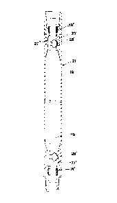
Fig.l shows a partly sectioned side view of a lower portion
of a drill string including drill string elements according
to the present invention; Fig.2 shows a partly sectioned
side view of an intermediate portion of a drill string
element according to the invention; Fig.3 shows a partly
sectioned side view of an upper portion of a drill string
including drill string elements according to the present
invention; Fig.4 shows an alternative embodiment of a drill
string element according to the invention especially
adapted for shorter rods; and Fig.5 shows an alternative
embodiment for means to prevent the rod of a drill string
element to fall out of said drill string element.
In Figs.1-3 a drill string 10 is shown, said drill string 10
including a drill bit 11, said drill bit 11 in the disclosed
embodiment consisting of two parts 12 and 13. On top of the
drill bit 11 a central set of rods 14 is resting, said set
including a number of rods 15 that have their ends loosely
abutting each other. The uppermost rod 15 in the set 14
carries a top hammer 16 that transfers impacts to the drill
bit 11 via the set of rods 14. The drill string 10 further
includes a set of tubes 17 that surrounds the set of rods
14, said set of tubes 17 including a number of tubular
members 18 that are secured to each other by thread
connections. As is apparent from Figs.1-3 the thread
connections are of two different types, i.e. every other
thread connection is conical and the rest of the thread
connections is cylindrical. The reason for using two
different types of thread connections is that by doing so
one normally can predict which thread connection will
unscrew first since conical thread connections 19 generally
are easier to loosen than cylindrical thread connections 20.
This means that the tube assemblies 21 that the operator
normally handles consist of two tubular members 18 having
conical threads at their ends. The cylindrical thread
connection 20 is unscrewed in principle only when the rods
15 are to be mounted within the tubular members 18 or when

1~1616~
repair or service of the equipment need to be done.
The aim of the set o~ tubes 17 is to transfer rotation to
the drill bit 11. For this purpose the drill bit 11 and the
frontal end of the set of tubes 17 are provided with
cooperating splines 22. The splines of the set of tubes 17
are provided in a bit sleeve 23 that via a cylindrical
thread connection 20 is coupled to the rest of the set of
tubes 17. The bit sleeve 23 is unscrewed when the lower part
12 of the drill bit 11 is replaced. This happens quite often
since it constitutes a wear part of the drill string 10. The
lower part 12 of the drill bit 11 is prevented from falling
out of the drill string 10 by a stop ring 24 that cooperates
with an enlarged portion 25 of the lower part 12.
The upper part 13 of the drill bit 11 is provided with a
flushing channel 26 extending transverse to the longitudinal
direction of the drill bit 11, said flushing channel 26
communicating with one or more internal flushing channels in
the drill bit ll. From the flushing channel 26 and upwards
there is a space between the set of rods 14 and the set of
tubes 17, said space transporting the flushing air from the
ground level.
As is appearent from Figs.1-3 the tubular members 18 are
provided with an internal diameter reducing 27 in connection
with the conical thread connections 19, said diameter
reducing being so dimensioned that it cooperates with a
radial projection 28 of the adherent rod 15 to prevent that
said rod 15 falls out of the tube assembly 21 during its
handling. Each tubular member 18 is provided with an
internal diameter reducing 27 in connection with both the
male and female part of the conical thread connection 19.
This guarantees that an adherent rod 15 is prevented from
falling out of the tube assembly 21 at both ends of said
assembly 21.
In connection with tke conical thread connection 19 the

4 13lfils~
tubular members 18 are provided with a guide means 29 for
the rod 15, said guide means 29 preferably being of
flexible material, e.g. polyurethane, thereby reducing
vibrations and noise of the device and simultanously
compensating for a certain lack of straightness of the rods
15.
As is apparent from Fig.2 a joint 30 between two rods 15 is
arranged at the level of the cylindrical thread connection
20 in the disclosed embodiment. The reason therefor is that
the rods 15 thereby get a length that can be handled. The
tubular members 18 are provided with guide means 31 in
connection with the joint 30 regardless whether it is a male
or female part. The guide means 31 have the corresponding
function as the guide means 29 described above and
preferably the guide devices 31 are made out of the same
material. The length of a tube assembly 21 between two
conical thread connections 19 of the structural design
described above is 3-6 m. In the area of the lower limit of
the interval it is possible to have the rod 15 in one piece
provided that the guide means 29 can be mounted properly.
The embodiment disclosed in Fig.4 is especially adapted for
tube assemblies 21' of shorter length, and consequently only
one rod 15' is mounted within the tube asssembly 21'. The
tubular members 18' and 18" have in this case a
substantially different length. This means that the
cylindrical thread connection 20' is located in connection
with one end of the tube assembly 21'. In accordance with
the embodiment described above both the tubular members 18'
and 18"
have internal diameter reducings 27' and 27" that cooperate
with radial projections 28' of the rod 15'.
In Fig.5 an alternative embodiment concerning means to
prevent the rod 15" from falling out of the tube assembly
21" is shown. In the area of its free ends the rod 15" has
portions 15a" of a reduced diameter. The transition between

13161S8
said portion 15a" and the rest of the rod 15" is defined by
shoulder means 2~" extending circumferentially around the
rod 15". The shoulder means 28" cooperate with a diameter
reducing 27 "' to prevent the rod 15" from falling out
downwards in Fig.5. The reduced diameter portion 15a" is
guided by guide means 29" of preferably flexible material.
The flushing medium is discharged in channels 3~ located
radially outside of the guide means 29".
Within the scope of the invention it is also possible that
each tube assembly holds three or more rods if the length of
the tube assembly is extremely big, e.g. towards about 11 m.
The above described embodiments refer to solid rods
15;15';15" and consequently the flushing medium passes
between the tubular members 18;18';18" and the rods
15;15';15". However, the invention is also applicable for
rods having internal, longitudinal flushing channels.
It is in no way necessary that one thread connection 19 is
conical while the other thread connection 20 is cylindrical.
The important feature is that the thread connections are
unequally easy to unscrew and this can e.g. be achieved by
different pitches fo the resp. thread connections.
Also in other aspe~ts the invention is in no way limited to
the embodiments described above but can be varied freely
within the scope of the appending claims.

Dessin représentatif
Une figure unique qui représente un dessin illustrant l'invention.
États administratifs

2024-08-01 : Dans le cadre de la transition vers les Brevets de nouvelle génération (BNG), la base de données sur les brevets canadiens (BDBC) contient désormais un Historique d'événement plus détaillé, qui reproduit le Journal des événements de notre nouvelle solution interne.

Veuillez noter que les événements débutant par « Inactive : » se réfèrent à des événements qui ne sont plus utilisés dans notre nouvelle solution interne.

Pour une meilleure compréhension de l'état de la demande ou brevet qui figure sur cette page, la rubrique Mise en garde , et les descriptions de Brevet , Historique d'événement , Taxes périodiques et Historique des paiements devraient être consultées.

Historique d'événement

Description Date
Inactive : Demande ad hoc documentée 1996-04-13
Le délai pour l'annulation est expiré 1995-10-15
Lettre envoyée 1995-04-13
Accordé par délivrance 1993-04-13

Historique d'abandonnement

Il n'y a pas d'historique d'abandonnement

Titulaires au dossier

Les titulaires actuels et antérieures au dossier sont affichés en ordre alphabétique.

Titulaires actuels au dossier
SANDVIK AB
Titulaires antérieures au dossier
KENNETH L. LARSSON
SVEN P. LILJEBRAND
Les propriétaires antérieurs qui ne figurent pas dans la liste des « Propriétaires au dossier » apparaîtront dans d'autres documents au dossier.
Documents

Pour visionner les fichiers sélectionnés, entrer le code reCAPTCHA :


Pour visualiser une image, cliquer sur un lien dans la colonne description du document. Pour télécharger l'image (les images), cliquer l'une ou plusieurs cases à cocher dans la première colonne et ensuite cliquer sur le bouton "Télécharger sélection en format PDF (archive Zip)" ou le bouton "Télécharger sélection (en un fichier PDF fusionné)".

Liste des documents de brevet publiés et non publiés sur la BDBC .

Si vous avez des difficultés à accéder au contenu, veuillez communiquer avec le Centre de services à la clientèle au 1-866-997-1936, ou envoyer un courriel au Centre de service à la clientèle de l'OPIC.


Description du
Document 
Date
(aaaa-mm-jj) 
Nombre de pages   Taille de l'image (Ko) 
Revendications 1993-11-10 2 75
Abrégé 1993-11-10 1 36
Page couverture 1993-11-10 1 11
Dessins 1993-11-10 3 55
Description 1993-11-10 5 196
Dessin représentatif 2002-02-15 1 4
Correspondance 1993-01-26 1 33
Correspondance 1989-07-28 1 36