Note : Les descriptions sont présentées dans la langue officielle dans laquelle elles ont été soumises.
131~731
MISSILE LAUNCHER
BACKGROUND OF THE INVENTION
1. Field of the invention
. . .
The present invention relates generally to a tube
launched missile, and, more particularly, to a launcher
for such a missile which substantially reduces both the
launch visual signature and the acoustic signature while
providing the capability of delivering a higher launch
velocity than conventionally obtained.
2. Description of Related Art
The conventional technique for launching a missile
fxom a tube is to utilize a rocket motor which is an
integral part of the missile. Such rocket motors must
be contained within a limited envelope because of the
need for space by other sub-systems, such as controls,
a beacon, wire bobbins, and the like, which usually must
occupy the same base region of the missile. To minimize
the motor envelope, it has been found necessary to rely
upon the use of high energy, fast burning propellants,
and high operating pressures.
Other apparatus have been suggested for launching
missiles from a launching tube or platform without the
use of rocket fuel. For example, United States Letters
Patent 4,333,382 describes a hydraulic actuating system
utilizing a high pressure piston stroke over a short
distance for accelerating a missile up to launch speed
- immediately prior to initiation of the missile motor.
.. ..
.
131~73~
1 Briefly, the patented apparatus includes a pneumatic/
hydraulic system to systematically and sequentially
remove restraining supports holding the missile to the
launcher, and a telescopic piston ass~mbly for driving
the missile to a predetermined initial ~elocity.
There are other methods and techniques which can
be generally referred to as "pneumatic", in which com-
pressed fluids such as air are used to propel the
missile into flight. For example, such techniques are
disclosed in U.S. Patents 3,605,549; 3,968,945; and
4,040,334. However, these techniques are all accompanied
by one or more disadvantages including the requirement
of external fasteners on the missiles which reduces
aerodynamic performance, high cost of maintenance, and
the necessity for cleaning the apparatus and launch tube
after a small number of firings thereby limi~ing the
number of missions an aircraft, for example, can make
before maintenance must be performed.
SUMMARY OF THE INVENTION
The launcher to be described achieves its most
advantageous utilization in providing initial powering
of a missile from an open-ended launch tube. This
launcher includes an elongate elastic bag which is
substantially gas tight in construction having dimensions
substantially identical to the interior dimensions of
the missile launching tube. One end of the launch bag
is closed and adapted to contact the aft end of the
missile when located in the launch tube. The opposite
end of the bag is open and sealingly secured to an
integrated inflator/thruster which, as will be described,
produces gas for rapidly filling and expanding the bag
that acts on the missile aft end to eject the missile
from the launch tube.
~L31673~
The inflator/thruster includes a housing having a
quantity of a solid propellant which on ignition produces
gases which flow through a foraminous diffuser into the
launch bag to inflate it. Simultaneously, gases exhaust
rearwardly through low pressure ports producing thrust
which balances the launch force eliminating recoil.
In an alternative embodiment, the launch bag closed
end is provided with a configured outer surface
complementary to that of the missile base in order to
accommodate specially shaped structures on the base.
Another aspect of this invention is as follows:
Apparatus for launching a missile, comprising:
an open-ended tube for receiving the missile there-
within, said tube being longer than the missile and having
fore and aft ends; a selectively actuatable pressurized gas
generator having external dimensions enabling sliding
receipt of the generator within the tube aft end, said
generator having a diffusor through which gas can move
along in a first direction and a plurality of openings
through which gas can move in a second direction generally
opposite to the first direction; and an expandable, air-
tight, bag-like member, said bag-like member having an
opening for receiving gas passing through the diffusor,
whereby expansion of said bag-like member causes said
missile to be launched from said tube.
.,
1 31 6731
4a
DESCRIPTION OF THE DRAWINGS
In the accompanying drawings:
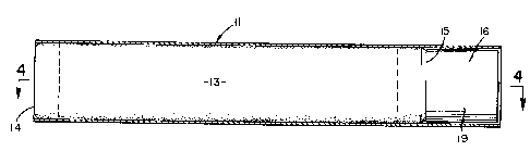
FIG. 1 is a side elevational~ partially
sectional view of a launch tube showing the invention prior
ts operation;
FIG. 2 is a side elevational, partially
sectional view similar to FIG. 1 except the launch bag of
the present invention is shown in expanded condition;
FIG. 3 is an enlarged, side elevational,
sectional view taken through the inflator/thruster of the
present invention along the line 3-3 of FIG. 1:
FIG. 4 is a side elevational, sectional view
taken along the line 4-4 of FIG. 2; and
FIG. 5 is an end elevational, sectional view
taken along line 5-5 of FIG. 1 looking directly into the
diffuser.
DESCRIPTION OF THE PREFERRED EMBODIMENTS
Turning now to the drawings and particularly FIGS.
1 and 2, a missile 10 to be launched from an open-ended
tube 11 conventionally has its own launch motor (not shown)
which may be a unitary part of the missile. Not only does
this arrangement raise questions
~3-16731
1 of efficiency and reduction in payload or the missile,
but such launchings are accompanied by relatively high
visual and aco~stic signatures which desirably should
be eliminated or reduced.
In its broadest contemplation, the launcher 12
of this invention includes a bag 13 having a closed end
14 and an opposite open end 15, the closed end being
located adjacent to the base of the missile when posi-
tioned within the launch tube 11 The open end 14 of the
bag is sealed to a gas generating inflator/thruster
16, which, upon ignition, provides a supply of pressur-
ized gas to the interior of the bag causing it to rapidly
expand and eject the missile. As will be more particu-
larly shown and described, the invention launches a
missile with a substantial reduction in the visual and
acoustic signature which reduces the possibility of de-
tection and the taking of countermeasures against the
missile.
The collapsible bag 13 is an elastic membrane pre-
ferably constxucted of a closely woven fabric such as
nylon forming a substantially non-porous sidewall, The
expanded bag is a cylindrical envelope having a closed
end 14 which can preferably be reinforced if required,
The closed end is contemplated for contact with the
missile aft end in use, so reinforcement may be needed
to prevent damage to or leakage of the bag Such
reinforcement may take several different forms, a pre-
ferred one of which is to use multiple layers of the nylon
fabric or other bag material
The opposite end 15 of the launch bag is open and
is of such a dimension relati~e to the thruster that it
can be received thereon and preferably sealed to the
thruster by a quantity of epoxy 17, for example, that
extends completely about the thruster. Alternatively t a
clamp ring (not shown) may be used to effect sealing
relation between the bag and the thruster.
13~6731
1 The lower end portion 18 of the bag open end is
preferably treated with a material which has good heat
insulation properties to protect the bag material from
excessive heat transfer during inflation. Suitable ma-
terials for this purpose include any polymeric material,
such as EPDM, for example. When fully in place upon the
thruster, the interior of the bag forms a substantially
gas tight plenum which is inflated by gases upon burning
a solid propellant. As seen best in FIG. 2, when the bag
13 is fully inflated it and the thruster 16 substantially
fill the missile launch tube.
For the ensuing description of the inflator/
thruster details, reference is now made to FIG. 3, in
which the inflator/thruster is seen to include a shell
casing 19 which has an outer diameter such that it can be
slidingly received within the launch tube 11. A diffuser
20 consisting of an arcuately shaped metal plate has a
diameter such that it can be fit within the inner end of
the thruster shell casing 19 and includes a plurality of
openings 21 for transmission of propellant gas, as will be
described. The diffuser plate is affixed to the inner
wall of the housing by any suitable means such as welding
or bonding, for example.
Although it is not believed that extra cooling of
the gases would be necessary in most cases, depending up-
on a variety of factors there may be circumstances inwhich a gas cooling section may be advisable. According-
ly, in the latter case immediately adjacent the diffuser
plate a quantity of granulated coolant material 22 such
as silicon dioxide (SiO2) may be provided, for example,
which would act to remove heat from the propellant gas as
it moves therethrough, and, in that way, reduce heat
applied to the bag during launch. Such a gas coolant bed
would be secured in place against the diffuser plate by a
wire mesh containment screen 23 and secured to the casing
inner wall surface by welding, or other suitable means.
' ~31~73~
1 A cylindrical wire mesh container 24 has one end
secured to the center of screen 23 and extends coaxially
rearward. A quantity 25 of a ~uitable solid propellant
is located within the container A low signature solid
propellant, such as sodium azide~ for example~ which has
a relatively low temperature on burning and is non-toxic,
is excellent for this purpose,
The propellant container is enclosed at its rear
by a plate 26 including a centrally located igniter 27.
The propellant containment plate has a plurality of open-
ings 28 which serve as nozzles in generating thrust to
equilibrate eject recoil,
In use, the thruster 16 with collapsed launch bag
13 is located in the lower end of the launch tube 11 and
the missile is placed within the tube resting its lower
end upon the bag end portion 14 as shown in FIG. 1. The
igniter 27 is then energized and the solid propellant on
ignition produces pressurized gas which passes through the
coolant material 22 (if used) and then through the diffu-
ser 20 rapidly expanding the launch bag to its fullyinflated condition as shown in FIG, 2
This expansion of the bag launches the missile
from the tube. At the same time that the bag is being
inflated, a precise predetermined amount of propellant
gases exit via the thruster nozzle openings or ports 28
in the direction opposite to missile launching which pro-
vides a necessary reaction to the launch recoil, A net
recoil force of substantially zero is obtained so that
there is no tendency for the inflator/thruster and inter-
connected launch bag to move rearwardly or out of thelaunch tube.
By use of the described invention, there is a
substantial reduction in the acoustic signature as well
as visual signat.ure which reduces the possibility of
detection of the missile launching and countermeasures
being taken. In view of the fact that the described
~3~7 31
1 launch system remains with the launch tube~ missile pay-
load capability is enhanced~ or alternatively~ missile
flight weight is reduced since the expended launch motor
is not carried to the target, Since the launch motor
S has been removed from the missile, there is additional
volume for controls, beacon, wire bobbins, or other
missile components.
Although the invention has been described in a
preferred form, it is to be understood that one skilled
in the appertaining art could utilize a modified form
and dif~erent components therein without departing from
the spirit of the invention For example~ the solid
propellant gas source could be replaced by a suitable
slow burning liquid propellant carried within a suitable
container. Also, although nylon fabric is preferred
for constructing the bag 13r a number of flexible or
elastic plastic materials or closely woven fabrics
would be satisfactory for this purpose.