Note : Les descriptions sont présentées dans la langue officielle dans laquelle elles ont été soumises.
3 n
AUXILIARY POWER SYSTEM
FOR TRUCKS AND OTHER HEAVY DUTY VEHICLES
The present invention relates generally to a auxiliary
power ~ystem for use in trucks and other heavy duty
vehicles, and particularly to a cogeneration system which
can provide heat to a primary engine for facilitating
restarting the primary engine in cold weather, as well as
auxiliary electrical power and air conditioning.
BACKGROUND OF THE INVENTION
The problem addressed by the present invention iB that,
during the w~nter, cross country truckers traditionally
idle their engines during ovsrnight rest stops to assure
cold weather restart and to provide heat in the aab. In
particular, to enable cold weather restart it is important
to keep the truck's motor oil and diesel fuel warm. As is
well known, motor oil provides proper engine lubricatlon
only within a limited temperature range, and diesel fuel
typically begin~ to wax at temperature~ below 40 de~rees
F~hrenheit and becomes a virtually unusable gel at
temperatures below 20 degrees Fahrenheit.
Idling the main truck ~ng~na overnight i~ ona way to k~ep
the truck' 8 motor oil and diesel fuel warm and to thereby
as ure cold weather restart. This use of the main truck
engine, however, is very inef~icient. Typical truck
engines, such as 300 to 500 ~HP Diesel engines, are very
inefficient when operated at 600 to 900 RPM at only 10 to
1 3 ~
- 2 -
20 BHP - i.e., the power level needed to idle the engine
and to drive the truck's electrical generator, cab heater
or air ccnditionar, and other cab acce6sories.
As provided by the present invention, one solution to the
problem of maintainlng a habitable environment in a truck
cab ov~xnight and keeplng the engine warm so that lt can be
re~tarted ~ter a cold winter'e night, iB to use ~ small
cogeneration ~ystem which can perform these functions more
efficiently than the truc~'s main engine. In particular,
the cogeneration sy6tem includes a ~upplemental engine
which supplies heat to certain engine components and also
supplies power to a selected set of cab accessories which
are normally powered by the main engine. Furthermore, the
supplemental engine of the present invention can and
preferably does use the same fuel supply as is used for the
main truck engine.
The prior art includes a number of supplementarv engine
systems, often called pony engines, for use in trucks.
See, for example, U.S. Patents 4,682,649 (Greer, 1987) and
4,448,157 (Eckstein et al., 1984). However, the prior art
pony engines have, generally, been too complicated,
expensive and insufficiently energy efficient to achieva
aignificant commercial success.
The present invention provides improved energy efficiency
and reduced complexity by interconnecting the fluid coolant
systQm6 of the truck's primary and auxiliary engines, and
using this interconnection as the sole mechanism for
providing heat to the primary engine and the truck'~ cab
and ~leeper heaters.
The present invention al80 provides improved auxillary air
conditioning by providing an ~uxiliary con~enser as well as
an auxiliary compressor, and electrical controls for selec-
tively enabling either the auxiliary or the primary
compressor. The electrical control allow the auxiliary
1 3 ~ 3 7;~ 3 `~
- 3 -
engine to drive the auxiliary compre6sor even when the
primary engine iB running, thersby allowing the air
conditioning load to be removed from the primary engine.
It is therefore a primary ob;ec of the present invention
to provide an improved auxiliary power syRtem for trucks
and other heavy duty vehicles.
Another ob~ect of the present invention is to provide a
truck cogeneration system that uses wa6te heat from an
auxiliary engine to heat the truck~ main engine, cab and
sleeper compartment.
SUMM~RY OF THE INVENTION
In summary, the present invention is an auxiliary power
system for a truck or other heavy duty vehicle. The
auxiliary 6ystem uses a secondary engine which i8 smaller
than the vehicle's main or primary engine and which i8 more
efficient than the vehicle's main engine at low energy
output levels.
The auxiliary engine includes a water ~acket which is
interconnected with the main engine's coolant system.
Coolant fluid flows through the auxiliary engine's water
~acket, drawing heat from the auxiliary engine. The
coolant then flows through the main engine's water ~acket,
thereby heating the main engine block. The coolant fluid
heated by the auxiliary engine is also used for heating the
truck's cab and sleeper compartments when the main engine
is not in u~e. The use of this auxiliary power ~ystem
permits the use of a ~mall ~nd efficient engine to keep the
truck'~ motor oil, fuel and cab warm and to power a variety
of cab accessorie~ without having to run the vehicle 1 6
primary engine.
In the preferred embodiment, the auxiliary engine also
drives an auxiliary alternator which charges the truck's
~ 3 ~
~ 4
batteries and provides lln volt a.c. power to the truck's sleeper
compartment.
Thus according to one broad aspect of the invention,
there is disclosed in a truck having a main engine having a water
jacket, and an air condi-tioning system including a primary
compressor, a primary condenser, at least one air conditioning
unit/ and refrigerant lines including a first refrigerant line
coupling the primary compressor to the primary condenser, an
outlet refrigerant line which delivers refrigerant from the
primary condenser to the air conditioning unit and an inlet
refrigerant line which returns refrigerant from the air
conditioning unit to the primary compressor; an auxiliary power
system comprising: a secondary engine smaller than and
independent of said main engine, said secondary engine having a
water jacket with an inlet for coolant fluid and an auxiliary
water pump which pumps coolant fluid out of said water jacket of
said secondary engine; auxiliary coolant lines including an
auxiliary coolant outlet line which routes coolant pumped by said
auxiliary water pump .into said water jacket of the main engine,
and an auxili.ary coolant inlet line which routes coolant fluid
from the water jacket of the main eng.ine into said water jacket of
said secondary engine; and an auxiliary air conditioning system
having: an auxiliary compressor, driven by said secondary engine,
having an inlet and an outlet, an auxiliary condenser having an
inlet coupled to said outlet of said auxiliary compressor and an
outlet; an auxiliary fan which cools said auxiliary condenser; and
auxiliary refrigerant lines connecting said auxiliary compressor
r~
~ 4a
and condenser to the air conditioning system in parallel with the
primary compressor, and in series with said primary condenser.
Accordlng to a ~urther broad aspect of the invention,
there is disclosed in a truck having a main engine and an air
conditioning system including a primary compressor, a primary
condenser, at least one air condi-tioning unit, and reErigerant
lines interconnecting the primary compressor, the primary
condenser, and said at least one air conditioning unit; an
auxiliary power system comprising: a secondary engine smaller
than and independent of said main engine; and an auxiliary air
conditioning system having: an auxiliary compressor driven by
said secondary engine, an auxiliary condenser having an inlet
coupled to said auxiliary compressor; an auxiliary fan which cools
said auxi]iary condenser; and auxiliary refrigerant lines
connecting said auxiliary compressor and condenser to the air
conditioning system in parallel with the primary compressor and in
series with said primary condenser.
BRIEF DESCRIPTION OF THE DRAWINGS
Additional objects and features of the invention will be
more readily apparent from the following detailed description and
appended claims when taken in conjunction with the drawings, in
which:
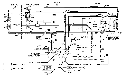
Figure 1 is a schematic drawing of a cogeneration system
in accordance with the invention.
Figure ~ depicts the electrical controls for the main
and auxiliary air conditioning compressors in the preferred
embodiment.
.' ~ .
~3~7~
4b
DESCRIPTION OF THE PREFERRED EM~ODIMENT
Fiqure 1 shows the primary components of an auxiliary
power system for providing heating, air conditioning and
electrical power to the cab 22, and sleeper 24 of a truck 20. An
auxiliary engine 30 is coupled to the truck's cooling, air
conditioning and electrical systems which are also coupled to the
truck's main or primary engine 26. This auxiliary engine 30 is
substantially smaller than and independent of the main engine 26,
and is used to provide power to selected preexisting accessories
when the main engine 26 is not in use. In the preferred
embodiment the auxiliary engine is a diesel 10 BHP engine such as
the Model 2B600 engine made by Kubota. More generally, auxiliary
engines w.ill generally be diesel fuel engines with capacities
between 5 and 25 BHP.
For the purposes of this specification, the term "truck"
is defined to include any heavy duty vehicle.
1 3 ~
- 5 -
Primary Engine and
Associated Equipment
In the preferred embodiment, before the addition of the
auxiliary power system, the truck is already eguipped with
the following components. As i8 standard, the truck~s
engine cooling 6y6tem includes a radiator 32 ln ~luid
connection with the ~acket of the main engine 26, and a
cooling fan 34. The main engine includes a control valve
tnot shown) that enables the flow of coolant fluid from the
main engine jacket through the radiator 32 only when a
thermostat indicate~ that the main engine'6 temperature
exceeds a specified temperature. A water pump 35 provides
the line pressure re~uired to ensure adequate circulation
of coolant fluid through the main engine's jacket and the
radiator 32.
The cab 22 and the sleeper 24 in the truck each have
heating units (i.e., heater cores) 36 and 37, and air
conditioning units 38 and 39. A refrigerant (i.e., freon
12, al~o known as R12) compressor 40 driven by the main
engine 26 provides high pressure freon to the air
conditioning units 38 and 39. Compressed freon flows from
this compressor 40 to a condenser 42, and then to a
receivar 44. In the preferred embodiment the receiver 44
i5 a freon dryer having a T-connection at its outlet BO
that freon is supplied by the receiver 44 to both the cab
and 61eepers air condition unit6 38 and 39.
Solenoid valve6 46 and 48 are used to control the flow of
freon into the air conditioning units 38 and 39 in the cab
22 and sleeper 24, respectively. Similarly, there are
~eparate expan6ion valves 50 and 52 at the inlet6 to the
cab and sleeper air conditioning unit~. Standard,
independent controls are used to open the 601enoid valve6
46 and 48 in accordance with 6election made by the sy6tem 16
u6er.
~ 3 ~
-- 6 --
As is standard in trucks and other vehicles, a flow control
valve 54 controls the flow of heated coolant fluid through
the he ter cores 36 and 37 in the cab and sleeper. The
amount of flow through valve 54 is controlled by a heat
level ~election lever 56 in the cab 22.
In the preferred embodiment ~here is al~o an electrically
powered fuel heater 58 ~urrounding the main engine 1 8 fuel
filter (not shown) for liquefying gelled diesel fuel in
cold weather. For trucks used in extremely cold climates a
~econd electrically powered fuel heater is added to the
fuel filter for the auxiliary engine 30. In an alternate
embodiment, a fuel heater could be provided for directly
heating the fuel tank 62.
It should be noted that a single cooling fan 34 i6 used to
cool both the main engine radiator 32 and the condenser 42.
This ~an 34 is controlled using a temperature sensor on the
output l~ne of the radiator 32, a pressure sensor on the
outlet of the ~reon dryer 44, and an manual override switch
in the cab 22. The fan 32 i6 automatically turned on under
any one of three conditions: (1) if the main engine is on
and the temperature of the main engine' s coolant ~luid
exceeds a speci~ied temperature, (2) if the pres~ure in the
on the outlet of the freon dryer 44 exceeds a specified
pressure level, or ~3) if a manual override switch is
closad (i.e., turnsd on) by the driver tn the truck's cab
22.
Auxiliary System
As discussed nbove, the main purpose of the auxiliary
engine 30 i8 to allow the use of a smaller and more
e~ficient engine to heat selected system components and to
drive selected accessorie3 when the main engine is not in
use. These selected components and accessories typically
include electrical accessories such as lights and fans,
components which use thermal energy ~uch as the cab and
dj st'~
- 7 -
~leeper heaters 36 and 37, and accessories which use
mechanical power such a6 an auxiliary freon compreesor 66.
The auxiliary engine 30 also acts as a cogeneration system
in that waste heat from the auxiliary engine 30 is used to
perform useful work - i.e., providing heat to the main
engine 26, the cab 22 and the sleeper 24. Furthermore,
both the main and secondary engines share the same fuel
6upply 62.
In the preferred embodiment, the auxiliary power system 30
i8 mounted in a modified version of the truck's tool box,
which is mounted on the truck's frame rail.
Electrical Generator. The auxiliary engine's crank 6haft
70 drives an auxiliary electrical generator 72 (i.e., an
alternator). In the preferred embodiment, the alternator
72 (e.g., the model 4.5KVA MARK3 alternator made by US
Energy) generates both 12 volts d.c., and 110 volts a.c.
The 12 volt d.c. output from the generator recharges the
truck's 12 volt battery 74, and the 110 volt a.c. output is
coupled to one or more outlets 76 in the sleeper 24 80 that
standard 110 volt accessories can be used in the sleeper.
Coolant Fluid System. ~he auxiliary engine 30 uses the
same coolant fluid as is used by the main engine 26. Thus
the same coolant fluid passes through the ~ackets of both
engines and, when the auxiliary engine is used, heat from
the auxiliary engine 30 i8 transferred to main engine 26,
thereby malntaining the main angine block at a temperature
which fa¢ilitatas easy ~tarting. Conversely, coolant will
~low through the auxiliary engine' 6 ~ acket when the main
engine 26 is running but the auxiliary engine 30 is off.
It ~hould be noted that in the preferred embodiment the oil
ln the main engine's crankcase is heated (so as to maintain
a proper oil viscosity for starting the main engine 26)
~ 3 ~ 3`~'
-- 8 --
801aly by the flow of hot coolant fluid through the main
engine 1 6 ~ acket.
The truck'~ coolant plumbing system, ~nd the dir~ction of
flow of coolant through the plumbing system, is identified
by solid arrows drawn next to the linss which carry
coolan~.
In the preferred embodiment, a hot exhaust heat exchanger
0 i6 not used to heat the truck~s coolant fluid because such
heat exchangers significantly increase the C06t, complexity
and maintenance costs of the auxiliary power system. All
cogeneration heat is provided directly by coolant fluid
flowing through the auxiliary engine's jacket. ~ot exhaust
from the auxiliary engine is expelled through exhaust line
80 and muffler 82, which are ceparate from the exhaust line
and muffler for the main engine.
The primary flow path of coolant fluid, when the auxiliary
engine 30 i6 turned on, is as follows. Coolant fluid in
the auxiliary engine's jacket is pumped into line 90 by an
auxiliary water pump 92 that operates only when the
auxiliary engine is on. The auxiliary water pump 92
provides the line pressure required to keep the coolant
flowing through the entire coolant plumbing system when the
main engine i8 off and only the auxiliary engine i8
running. Water pump 92 may be built into the auxiliary
engine 30 or it may be driven by belt or other mechanical
means coupled to the auxiliary engine' B drive ~haft 70.
From line 9o, coola~t flow6 through a one way check valve
94 into a T-valve 96 and then into the water ~acket 98 of
the main engine 26. Coolant leaves the main engine's water
~acket 98 at outlet 100, flow~ng into plumbing lines 102
and 104. L$ne 102 direct~ coolant fluid to the heat core~
36 and 37, and thus coolant flows through this line only to
the extent that heating control valve 5~ is open. Coolant
returning from the radiators flows through line 106, one
& ~
g
way ch~ck valve 108 and then through T-valve 96 back to the
main engine's water jacket 98.
Coolant fluid line 104 directs coolant exiting the main
eng~ne'e ~acket into the auxlliary engine's water ~acket
110. AB explained above, the coolant exit~ the auxiliary
engine' 8 water ~acket through the auxiliary water pump 92.
Check valves 94 ~nd 108 prevent coolant ~luid leaving the
auxiliary engine from flowing toward the heater cores 36
and 37 in opposition to the normal flow of coolant through
the plumblng system. Furthermore, when the main engine i8
on and the auxiliary engine is off, these check valves
ensure that while coolant flows through the auxiliary
engine'6 water jacket 110 (thereby enabling ea~y starting
of the auxiliarv engine in cold weather and also helping to
dissipate waste heat generated by the main engine), the
auxiliary system does not interfere with the normal flow of
coolant through the plumbing ~ystem.
As noted above, coolant in the main engine'~ water ~acket
98 will flcw through radiator 32 only when a thermostat in
the main engine opens a valve between the main engine's
water jacket 98 and the radiator 32. This valve will open
at the thermostat's ~et point even if the main engine is
off. The inventors have found that even though the
radiator cooling fan 34 and the main engine' 8 water pump 35
are not turned on when the main engine i8 off, the radiator
32 will di~sipate enough heat when only the auxiliary
engine 30 i8 running to maintain the coolant fluid at an
acceptable temperature.
In an alternate ~mbodiment, exce6sive heating of the
coolant fluid could be ~urther prevented by providing a
~mall, auxiliary radiator between the auxiliary water pump
92 and check valve 94, ~long with an electric fan for
cooling the aux~liary radiatox. In yet another alternate
embodiment, a safety ~witch could be provided in the
13.~ Q
-- 10 --
auxiliary engine which would turn off the auxiliary engir.e
in the event that the coolant temperature exceeded ~ preset
limit.
Auxiliary Air Conditioning. The auxiliary engine 30 drives
an auxiliary freon compressor 120 80 that air conditioning
can be provided to the cab and 61eeper when the main engine
26 is off. The auxiliary compressor 120 i6 driven by the
auxiliary engine's drive shaft 70. As is standard in many
vehicular compressors, the compressor's drive ~haft i8 COU-
pled to the compressor drive belt by a magnetic clutch (not
shown) ~o that the compressor 120 can be turned on and off.
Note that the terms refrigerant and freon are used inter-
lS changeably in this specification. As will be understood bythose 6killed in the art, the freon ~nd assoclatQd
components ueed in the preferred embod~ment could be
replaced with another refrigerant and corresponding
components in alternate embodiment6 of the present
invention.
The electrical control for the main and auxiliary
compressors is shown in Figure 2. The truck's normal
on/off and air conditioning thermostatic switches 122, 124,
126 and 128 and solenoid valves 46 and 48 are retained.
However, a relay 130 is added for switching between the
~ain and auxiliary compressors 40 and 120. When the
auxiliary engine 30 is on, main/aux switch 132 i6 closed,
thereby anabling the auxiliary compressor 120 to be
energized: when the auxiliary engine 30 is off, the switch
132 i6 opened, enabling the main compressor 40 to be
energized.
Note that the diodes Dl and D2 shown in Figure 2 prevent
the corre~ponding solenoid valves (46 and 48, respectively)
from being opened when the corresponding on/off switch (122
or 124) is ~n the off position.
~ 3 ~ J ~:,
-- 11 --
Referring back to Figure 1, the flow of refrigerant though
the air conditioning system is as follows. When the main
engine 26 and its compressor 40 are on and the auxiliary
engine 30 and the auxiliary compres60r 120 are off, com-
pressQd freon leaves compressor 40 and flows into condenser42 via T-valve 140 and line 142. From the condenser 42,
freon flows through refrigerant line 144 into receiver 44.
If solenoid valve 46 i6 open, freon i5 released through
expansion valve 50 into the cab's air conditioning unit 38.
From there, the freon returns through T-valve 146,
refrigerant line 148 and T-valve 149 to the inlet of the
compressor 40.
If ~olenoid valve 48 iB open, freon i6 released through
expansion valve 52 into the sleeper'6 air conditioning unit
39. From there, the freon returns through T-valve 146 and
line 148 to the inlet of the compressor 40.
When the auxiliary engine 30 i8 on, the main engine'e com-
pres60r 40 i5 disablQd by switch 132, and thus only the
auxillary compressor 120 can be used for air conditioning.
Compres~ed freon leaving compressor 120 and flows into an
auxiliary condenser 156 through line 157. An auxiliary fan
158 is provided for cooling the freon in the auxiliary con-
denser 156. This fan 158 is automatically turned on if
auxiliary compressor 120 is on and the pres6ure in the
outlet of the freon dryer 44 exceeds a specified pressure
level. In an alternate embodiment, the fan 158 iB mounted
on the shaft of the auxiliary alternator 72 so that the fan
158 w~ll run whenever the auxiliary engine i8 on.
It should be noted that the use of a roof top condenser
would be more expensive than one located closer to the
auxillary rreon compressor 120, and that the increasingly
prevalent use of aerodynamic air foils has eliminated the
room on the truck' B roof for a condenser. Also, it i8
generally impractical to depend on the main condenser 42
for condensing when the main engine is off because the main
1 3 ~
- 12 -
fan 34 cannot run when the main engine i8 off and there is
usually no room near the main engine' B fan 34 for an
additional electrically powered fan for cooling the main
condenser 42.
From the condenser 156, freon travels throu~h line 152 to
T-valve 140, through the main condenser 42 for additional
condensing (even though the main engine fan 34 is off when
the main engine 26 is off), and then through substantially
the same path used when the main compressor 40 is being
used. However, the returning freon in line 148 is drawn
down line 150 back into the compressor 120.
The freon plumbing system in the present invention is de-
signed so that back flow restriction valves are not neededbetween the two compressors 40 and 120. While gaseous
freon can enter the lines leading to a compressor which is
not turned on, these lines are evacuated by the compressor
that is on. The outlets of the two compressors need not be
protected with back flow restriction valves because
refrigerant compressors, such as the ones used in
automotive air conditioning systems, already contain a
pressure valve at the compre6sor's outlet which remains
closed when there i5 no pressure on the valve from inside
the compres60r.
In general, the auxiliary system used in the present inven-
tion is substantially more reliable and therefore less
expensive to maintain than the prior art auxiliary systems.
The auxiliary sy~tem's air conditioning derives $ts
improved reliability from tl) the use of simple, well
placed connections (the auxiliary equipment interfaces with
the other air conditioning equipment ~olely at T-valves 140
and 149), and (2) the use of an auxiliary condenser 156
with its own fan 158. The auxiliary air conditioning
system also makes use of the main condenser 42 in addition
to the auxiliary condenser 156, which significantly
improves the efficiency of the auxiliary air conditioning
~ 3~ X~
~y~tem. The u~e of two condenser~ i~ accomplished by an
usual parallel connection design, in which both the
auxiliary compressor 120 and the auxlliary condenser 156
are connected in parallel with the primary compressor 40
but in serieæ with the primary condenser 42.
The auxiliary air conditioning sys~em also provides a
*eature not found in other auxiliary power systems - the
ability to run the truck' 6 air conditioner using an
auxiliary engine while the primary engine is in operation.
Thus, when the truck is heavily loaded and/or going up long
steep grades, the air conditioning load can be removed from
the main engine without having to forego air condition in
the truck's cab.
Another advantage of the present invention is that the flow
pattern of the combined ~oolant systems, and the use of the
auxiliary engine' 6 water jacket as the sole heat
cogeneration source~ provides an integrated coolant
plumbing and cogeneration system which i5 highly reliable.
While the present invention has been described with
reference to a few speciflc embodiments, the description is
illustrative of the invention and i8 not to be construed a~
limiting the invention. Various modifications may occur to
those skilled in the art without departing from the true
spirit and scope of the invention as defined by the
appended claims.
For inst~nce, in th~ preferred embodimont thers i8 no
special provision made for heating the fuel tank b~cause
the heat generated by running the auxili~ry engine 30 has
been found to be suffic~ent to keep the diesel fuel from
gelling. However, in an altexnate embodiment for colder
environments, an electrical heater ~such the heater sold
under the trademark HOTLINE by Peterbilt Motors Company) is
provided for heating the fuel tank 62 to prevent the fuel
therein from gelling at low temperatures.