Sélection de la langue

Search

Sommaire du brevet 1316846 

Énoncé de désistement de responsabilité concernant l'information provenant de tiers

Une partie des informations de ce site Web a été fournie par des sources externes. Le gouvernement du Canada n'assume aucune responsabilité concernant la précision, l'actualité ou la fiabilité des informations fournies par les sources externes. Les utilisateurs qui désirent employer cette information devraient consulter directement la source des informations. Le contenu fourni par les sources externes n'est pas assujetti aux exigences sur les langues officielles, la protection des renseignements personnels et l'accessibilité.

Disponibilité de l'Abrégé et des Revendications

L'apparition de différences dans le texte et l'image des Revendications et de l'Abrégé dépend du moment auquel le document est publié. Les textes des Revendications et de l'Abrégé sont affichés :

  • lorsque la demande peut être examinée par le public;
  • lorsque le brevet est émis (délivrance).
(12) Brevet: (11) CA 1316846
(21) Numéro de la demande: 1316846
(54) Titre français: FERMETURE DE BOUT POUR CONTENANT
(54) Titre anglais: END CLOSURE FOR A PACKAGING CONTAINER
Statut: Périmé et au-delà du délai pour l’annulation
Données bibliographiques
(51) Classification internationale des brevets (CIB):
  • B65D 17/28 (2006.01)
  • B65D 17/34 (2006.01)
  • B65D 17/40 (2006.01)
  • B65D 41/50 (2006.01)
  • B65D 47/36 (2006.01)
  • B65D 51/18 (2006.01)
(72) Inventeurs :
(73) Titulaires :
  • AB AKERLUND & RAUSING
(71) Demandeurs :
  • AB AKERLUND & RAUSING (Suède)
(74) Agent: MARKS & CLERK
(74) Co-agent:
(45) Délivré: 1993-04-27
(22) Date de dépôt: 1989-02-14
Licence disponible: S.O.
Cédé au domaine public: S.O.
(25) Langue des documents déposés: Anglais

Traité de coopération en matière de brevets (PCT): Non

(30) Données de priorité de la demande:
Numéro de la demande Pays / territoire Date
8800512-9 (Suède) 1988-02-16

Abrégés

Abrégé anglais


ABSTRACT
An end closure for a packaging container where the closure is
of the basic type having a so called one step opening arrange-
ment, i.e. where an outer layer and an inner layer are
removed in unison or simultaneously by shaping the tearing
denotations in a proper pattern.
In order to provide an opening procedure giving less splash
the outer layer is divided into a central part having a grip
for individually removing the central part from the inner
layer laying under the outer layer without being connected
thereto.
A circumferentially extending region all around the closure,
is defined by said circumferential tearing denotation and the
central part and is removable together with the inner layer
inside the tearing denotation.

Revendications

Note : Les revendications sont présentées dans la langue officielle dans laquelle elles ont été soumises.


THE EMBODIMENTS OF THE INVENTION IN WHICH AN EXCLUSIVE
PROPERTY OR PRIVILEGE IS CLAIMED ARE DEFINED AS FOLLOWS:
1. An end closure for a packaging container comprising:
at least an outer layer and an inner layer, said outer
layer having a circumferential rim defining an outer
periphery of said end closure, and an easy opening device
integrally attached thereto, said rim and said easy opening
device being joined in the proximity of at least a first
circumferential tearing denotation spaced inwardly from said
rim, said easy opening device having a first tearing strip
defined by said first circumferential tearing denotation, a
second circumferential tearing denotation spaced inwardly
from said first circumferential tearing denotation, and an
intermediate tearing denotation joining said first and said
second circumferential tearing denotations, said first
tearing strip further defining a first grip, and said easy
opening device having a second tearing strip defined by said
second circumferential tearing denotation and a substantially
semicircular tearing denotation spaced inwardly from said
second circumferential tearing denotation, said second
circumferential tearing denotation and said substantially
semicircular tearing denotation being attached to a second
grip, and wherein said inner and said outer layers are
attached at a joint at least at both sides of said first
circumferential tearing denotation, said joint between said
outer and said inner layer being stronger than the tearing
strength of said inner layer.
2. The end closure of claim 1, wherein said inner layer
is a thin layer of high barrier material.
3. The end closure of claim 2, wherein said inner layer
is a metal foil.
4. The end closure of claim 1, wherein said outer layer

is generally thicker than said inner layer of injection
mouldable material.
5. An end closure for a packaging container comprising
an outer layer and an inner layer, said outer layer including
a circumferential rim defining an outer periphery of said end
closure and an easy opening device including a plurality of
tearing strips, said rim and a first tearing strip of said
plurality of tearing strips being integrally joined in the
proximity of a first circumferential tearing denotation
spaced inwardly from said rim, and said first tearing strip
of said plurality of tearing strips being integrally joined
to a second tearing strip of said plurality of tearing strips
in the proximity of a second circumferential tearing
denotation spaced inwardly from said first circumferential
tearing denotation, and wherein said inner layer is joined to
at least said circumferential rim and said first tearing
strip of said plurality of tearing strips of said outer
layer, said joint between said outer layer and said inner
layer being stronger than the tearing strength of said inner
layer.
6. The end closure of claim 5, wherein said inner layer
is a thin layer of high barrier material.
7. The end closure of claim 6, wherein said inner layer
is a metal foil.
8. The end closure of claim 5, wherein said outer layer
is generally thicker than said inner layer of injection
moldable material.
9. The end closure of claim 5 wherein said first
tearing strip of said plurality of tearing strips is provided
with a grip.
10. The end closure of claim 5 wherein said first

tearing strip of said plurality of tearing strips is provided
with a grippable surface at an end thereof.
11. The end closure of claim 5 wherein said second
tearing strip of said plurality of tearing strips is provided
with a grip.

Description

Note : Les descriptions sont présentées dans la langue officielle dans laquelle elles ont été soumises.

- ~3163~6
The present invention relates to an end closure for a
packaging container and more precisely that type of.closure
which allows a unison or simultaneous removal of at least two
layers, an outer layer and an inner layer, and which is
designed specifically for mastering any splash tendencies
when opening a filled packaging container closed hy an end
closure.
The state of the art literature is filled up with a variety
of container closures. As far as multi layer closures are
concerned, there are basically at least two main types, one
where the end closure is penetrated in two steps, implying
that the outer layer is first removed by a grip device and a
tearing denotation, whereafter the inner layer is punctured,
normally with any type of pointed object, and a second type
where the outer layer and inner layer are removed in unison
or simultaneously. Frequently, the former type of cover is
identified as a two step cover and the latter one as a one
step cover.
The technique of using a weld joint, adhesive joint or other
connecting means at both sides of a tearing denotation,
generally with a minor extension crosswise the tearing
denotation is well established and a number of different
techniques have been developed for providing and controlling
the strength relations between the inner layer and the weld
joint along the tearing denotations.
As mentioned at the introduction, splash sometimes will make
it more difficult to handle the said one step end closures,
resulting in an uncontrollable splashing and contamination.
'~
`~r~

" 1316~,~6
Thus, the invention provides an end closure for a packaging
container, comprising at least an outer and an inner layer,
where the outer layer has an easy opening arrangement having a
grip and a tearing denotation starting therefrom, said denota-
tion having a portion extending circumferentially the whole
way around the end closure close to a circumferential rim, and
where the inner layer is attached to the outer layer at bo~h
sides of the circumferential denotation and the joint between
the outer layer and the inner layer is stronger than the
téaring strength of the inner layer.
The container closure is characterized in that the outer layer
is divided into a central portion having a grip for indivi-
dually removing the central portion from the inner layer, lay-
ing below the outer layer but not connected thereto, and in
that a circumferentially, all around the closure extending
region of the outer layer is defined by said circumferential
tearing denotation and the central portion and is removable
together with the inner layer inside the tearing denotation,
by means of a grip portion arranged in the circumferential
region for allowing tearing along the circumferential tearing
denotation.
In one embodiment the circumferential, all around the end clo-
sure extending region of the outer layer is strip shaped and
is provided with a grip or grip facilitating surface at one
end thereof.
The arrangement according to the present invention is espe-
cially useful in applications where the inner layer is a thin
layer of a high barrier material, for instance metal foil, and
the outer layer is a layer of thicker material, for instance
plastics, for mechanically protecting the inner layer.
The invention will now be exemplified by reference to the
accompanying drawings, where
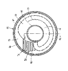
Fig. 1 is a view from above of a closure for a packaging
container,
~ .
.

- 131 h~'~6
Fig. 2 is a partial section along line II-II in Fig. 1.
The closure or so called end closure in Fig. 1 is use-ful not
only for closing container ends but, of course, the closure
may be used ~or whatever container having a proper connecting
piece or corresponding for the said object.
The container 10 in Fig. 1 comprises two layers, one outer
layer 11 and an inner layer 12. The outer layer 11 is formed
by an injection mouldable material, for instance plastics, or
another type of material allowing a similar advantageous and
economic manufacturing -technique. However, it should be noted
that the wall thickness o~ the outer layer is small, one or a
few millimetres in the thicker regions and some tenths of a
millimetre in the area of the tearing denotations. The injec-
tion moulding technique that has been suggested involves a
number of technical subsolutions which as such are not neces-
sary for an understanding of the structure of the closure in
Fig. 1, but further teaching may be found in parallel patent
applications filed the same day as this application.
The element 11 forming the outer layer comprises a central
cover panel or part 13 which radially outwards is defined by a
tearing denotation 14. In said element 13 there is a further
tearing denotation 15 which, like the denotation 14, starts
from a grip in the shape of a pull ring 16.
The region below the central element 13, i.e. the region
between said element and the inner layer 12 is completely un-
sealed to the inner layer and does not have any other type of
interconnecting portion, meaning that the element 13 is re-
leasable from the closure as soon as the tearing up by means
of the pull ring 16 along the tearing denotation 14, 15 has
been completed.
~-
Such an initial tearing away of central portion having a rela-
tively large area means that the product, for instance liquid,
inside the container closed by the closure, at a following
:
-
~. :
~ ~ .
. . :.
- ~

1 31 68~6
step including the removal of the remaining strip shaped
outer layer element 17, does not create such a heavy movement
of the product as the direct removal of an outer layer
covering 100% of the opening area together with the inner
layer. Thus the inner layer is able to prevent any spill
which might otherwise result from the removal of the second
tearing strip.
The strip 17 has a short tearing denotation portion 18 which
merges into the circumferential tearing denotation 19
extending all around the closure.
The strip end which is gripped at the tearing operation has a
number of ribs 21 for facilitating the grip.
As appears from Fig. 1 the strip portion 17 merges into a
circumferential rim 18 at said tearing denotation 19. The
inner layer 12, for instance a plastics coated aluminum foil
is attached to the outer layer 10 in a radially narrow region
at both sides of the tearing denotation 19. Such an
attachment may be obtained by the type of induction welding
technique or a high frequency welding that is described in
the prior art. Of course, if so desired, a radially broader
region may be attached to the outer layer, however, this does
not normally facilitate a one step tearing up operation.
Basically, there is nothing that forbids the attachment of
the entire area of the inner layer 12 to the outer layer lO,
however, this will then of course make the tearing up along
the different tearing denotations heavier and more difficult.
.,

Dessin représentatif
Une figure unique qui représente un dessin illustrant l'invention.
États administratifs

2024-08-01 : Dans le cadre de la transition vers les Brevets de nouvelle génération (BNG), la base de données sur les brevets canadiens (BDBC) contient désormais un Historique d'événement plus détaillé, qui reproduit le Journal des événements de notre nouvelle solution interne.

Veuillez noter que les événements débutant par « Inactive : » se réfèrent à des événements qui ne sont plus utilisés dans notre nouvelle solution interne.

Pour une meilleure compréhension de l'état de la demande ou brevet qui figure sur cette page, la rubrique Mise en garde , et les descriptions de Brevet , Historique d'événement , Taxes périodiques et Historique des paiements devraient être consultées.

Historique d'événement

Description Date
Inactive : CIB de MCD 2006-03-11
Inactive : Demande ad hoc documentée 1996-04-27
Le délai pour l'annulation est expiré 1995-10-29
Lettre envoyée 1995-04-27
Accordé par délivrance 1993-04-27

Historique d'abandonnement

Il n'y a pas d'historique d'abandonnement

Titulaires au dossier

Les titulaires actuels et antérieures au dossier sont affichés en ordre alphabétique.

Titulaires actuels au dossier
AB AKERLUND & RAUSING
Titulaires antérieures au dossier
S.O.
Les propriétaires antérieurs qui ne figurent pas dans la liste des « Propriétaires au dossier » apparaîtront dans d'autres documents au dossier.
Documents

Pour visionner les fichiers sélectionnés, entrer le code reCAPTCHA :


Pour visualiser une image, cliquer sur un lien dans la colonne description du document. Pour télécharger l'image (les images), cliquer l'une ou plusieurs cases à cocher dans la première colonne et ensuite cliquer sur le bouton "Télécharger sélection en format PDF (archive Zip)" ou le bouton "Télécharger sélection (en un fichier PDF fusionné)".

Liste des documents de brevet publiés et non publiés sur la BDBC .

Si vous avez des difficultés à accéder au contenu, veuillez communiquer avec le Centre de services à la clientèle au 1-866-997-1936, ou envoyer un courriel au Centre de service à la clientèle de l'OPIC.


Description du
Document 
Date
(aaaa-mm-jj) 
Nombre de pages   Taille de l'image (Ko) 
Abrégé 1993-11-11 1 20
Dessins 1993-11-11 1 23
Revendications 1993-11-11 3 94
Description 1993-11-11 4 160
Dessin représentatif 2001-12-18 1 12
Correspondance 1992-01-13 1 65
Correspondance 1993-02-09 1 36
Correspondance 1995-06-04 1 29