Sélection de la langue

Search

Sommaire du brevet 1316898 

Énoncé de désistement de responsabilité concernant l'information provenant de tiers

Une partie des informations de ce site Web a été fournie par des sources externes. Le gouvernement du Canada n'assume aucune responsabilité concernant la précision, l'actualité ou la fiabilité des informations fournies par les sources externes. Les utilisateurs qui désirent employer cette information devraient consulter directement la source des informations. Le contenu fourni par les sources externes n'est pas assujetti aux exigences sur les langues officielles, la protection des renseignements personnels et l'accessibilité.

Disponibilité de l'Abrégé et des Revendications

L'apparition de différences dans le texte et l'image des Revendications et de l'Abrégé dépend du moment auquel le document est publié. Les textes des Revendications et de l'Abrégé sont affichés :

  • lorsque la demande peut être examinée par le public;
  • lorsque le brevet est émis (délivrance).
(12) Brevet: (11) CA 1316898
(21) Numéro de la demande: 1316898
(54) Titre français: ROBINET DE CHASSE
(54) Titre anglais: FLUSHOMETER RELIEF VALVE
Statut: Périmé et au-delà du délai pour l’annulation
Données bibliographiques
(51) Classification internationale des brevets (CIB):
  • F16K 31/145 (2006.01)
  • E03D 3/06 (2006.01)
(72) Inventeurs :
  • WHITESIDE, JOHN F. (Etats-Unis d'Amérique)
(73) Titulaires :
  • SLOAN VALVE COMPANY
(71) Demandeurs :
  • SLOAN VALVE COMPANY (Etats-Unis d'Amérique)
(74) Agent: RICHES, MCKENZIE & HERBERT LLP
(74) Co-agent:
(45) Délivré: 1993-04-27
(22) Date de dépôt: 1989-07-13
Licence disponible: S.O.
Cédé au domaine public: S.O.
(25) Langue des documents déposés: Anglais

Traité de coopération en matière de brevets (PCT): Non

(30) Données de priorité de la demande:
Numéro de la demande Pays / territoire Date
242,549 (Etats-Unis d'Amérique) 1988-09-12

Abrégés

Abrégé anglais


IMPROVEMENTS IN FLUSHOMETER RELIEF VALVE
Abstract of the Disclosure
This invention relates to a flexible diaphragm assem-
bly for use in a flush valve having a hollow body, an inlet, an
outlet, a valve seat formed in the body between the inlet and
outlet, and an operating handle assembly. The diaphragm assem-
bly includes a diaphragm adapted to be peripherally attached to
the flush valve body and a barrel integral with the diaphragm.
The barrel has a seal member on its exterior positioned for
sealing engagement with the body valve seat. There is an annu-
lar valve seat on the interior of the barrel and a relief valve
is positioned within the barrel and has a seat portion positioned
to close upon the barrel valve seat. The relief valve has an
annular flexible lip in contact with the interior of the barrel
and spaced from the relief valve seat portion. The relief valve
further has a stem extending outwardly from the barrel and
positioned for contact by the flush valve handle assembly.

Revendications

Note : Les revendications sont présentées dans la langue officielle dans laquelle elles ont été soumises.


The embodiments of the invention in which an exclusive
property or privilege is claimed are as follows:
1. In a flush valve of the type having a hollow body,
an inlet, an outlet, a valve seat formed in the body between the
inlet and outlet, a diaphragm peripherally fixed to said flush
valve body, a barrel, integral with said diaphragm, a seal mem-
ber on the exterior of said barrel and positioned to close upon
said valve seat,
an annular valve seat on the inside of said barrel,
a relief valve positioned for movement within said barrel and
having an exterior portion thereof formed and adapted to close
upon said barrel valve seat, said relief valve having an annu-
lar outwardly-extending lip spaced from said exterior portion
and in sealing contact with the interior of said barrel, said
flush valve having an operating handle assembly, a portion of
which is formed and adapted to contact said relief valve, caus-
ing said relief valve exterior portion to move away from said
barrel valve seat and causing said relief valve lip to move,
at least in part, away from the interior of said barrel, pro-
viding for operation of said flush valve.
2. The flush valve of claim 1 further characterized
by and including a bypass orifice in said barrel, and a seal
member positioned at said bypass and extending about the exter-
ior of said barrel.
3. The flush valve of claim 2 further characterized
in that said bypass orifice is closely adjacent to said dia-
phragm.
4. The flush valve of claim 1 further characterized
in that said barrel has a portion thereof of reduced exterior
diameter, said barrel exterior seal member being positioned
about said barrel in the area of said portion of reduced diam-
eter.

5. The flush valve of claim 4 further characterized
in that said body valve seat is annular and is of a size to
receive only that portion of the barrel having a reduced exter-
ior diameter.
6. The flush valve of claim 1 further characterized
in that said diaphragm has an integral stress control ring formed
therein intermediate the barrel and the exterior of said dia-
phragm.
7. The flush valve of claim 1 further characterized
in that said relief valve has an axial stem extending beyond
said barrel and positioned to be contacted by said portion of
said operating handle assembly.
8. The flush valve of claim 1 further characterized
in that said barrel has a plurality of axially extending, cir-
cumferentially positioned, flow control slots formed therein.
9. A flexible diaphragm assembly for use in a flush
valve having a hollow body, an inlet, an outlet, a valve seat
formed in the body between the inlet and outlet, and an operat-
ing handle assembly,
said diaphragm assembly including a diaphragm adapted
to be peripherally attached to the flush valve body, a barrel
integral with said diaphragm and having a seal member on the
exterior thereof positioned for sealing engagement with said
body valve seat, an annular valve seat on the interior of said
barrel and a relief valve positioned within said barrel and
having a seat portion thereof positioned to close upon said
barrel valve seat, said relief valve having an annular flexible
lip in contact with the interior of said barrel and spaced from
said relief valve seat portion, said relief valve having a stem
extending outwardly from said barrel and positioned for contact
by the flush valve handle assembly.

10. The flexible diaphragm assembly of claim 9 fur-
ther characterized by and including a bypass orifice in said
barrel.
11. The flexible diaphragm assembly of claim 10 fur-
ther characterized by and including an annular seal member
positioned about said barrel and at least in part masking said
bypass orifice.
12. The flexible diaphragm assembly of claim 9 fur-
ther characterized by and including a stress control ring,
integrally formed with said diaphragm.
13. The flexible diaphragm assembly of claim 12 fur-
ther characterized in that said stress control ring is general-
ly intermediately positioned on said diaphragm and has portions
extending axially in both directions from said diaphragm.
14. The flexible diaphragm assembly of claim 9 fur-
ther characterized in that the exterior of said barrel has a
portion of reduced diameter, said barrel seal member being
positioned about said barrel portion of reduced diameter.
15. The flexible diaphragm assembly of claim 9 fur-
ther characterized in that said barrel has a portion of reduced
interior diameter, with said barrel valve seat being positioned
at the termination of said barrel portion of reduced interior
diameter.
16. The flexible diaphragm assembly of claim 15 fur-
ther characterized in that said barrel portion of reduced in-
terior diameter has a plurality of axially-extending flow
control slots formed therein.
17. The flexible diaphragm assembly of claim 9 fur-
ther characterized in that said relief valve seat portion is
directly adjacent said relief valve stem, with said relief valve
flexible lip being formed at the end of said relief valve away
from said relief valve stem.

18. The flexible diaphragm assembly of claim 9 fur-
ther characterized in that said diaphragm, barrel, and relief
valve are all formed of plastic.

Description

Note : Les descriptions sont présentées dans la langue officielle dans laquelle elles ont été soumises.

1 31 6~q3
Summary of the Invention
The present invention relates to a fl~lsh valve of
the type used in commercial washrooms and in particular to an
improved flexible diaphragm assembly for use in such a flush
valve.
A primary purpose of the invention is a flush valve
of the type described which has an improved diaphra~m assemblyl
substantially reducing the number of components within the flush
valve, thereby reducing piece-part costs, labor assembly costs
and inventory costs.
Another purpose is a reliably operable flexible dia-
phragm assembly of the type described in which all of the parts
are formed of a suitable plastic.
Other purposes will appear in the ensuing specifica-
tion, drawing and claims.
Brief Description of the Drawings
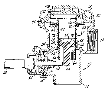
The invention is illustrated diagrammatically in the
attached drawing illustrating a preferred embodiment of the
invention.
Description of the Preferred Embodiment
The present invention is assigned to the assignee
of U.S. Patent 4,327,g91, Sloan Valve Company, of Franklin Park,
Illinois, which manufactures and sells flush valves for use
in commercial washrooms of several types, including those sold
under the trademarks ROYAL and CROWN. The '891 patent shows
a flush valve of the type sold under the trademark ROYAL and
the present invention is specifically directed to a diaphragm
assembly which may be usable in the flush valve of the '891
patent. The diaphxagm assembly is substantially improved over
that shown in the prior art, particularly in reducing the num-
ber of parts, and in forming the diaphragm assembly out of parts
~hich may be easily molded from one of the new generation of
' , :

13~689~
plastics, specifically a plastic sold by DuPont under the
trademark HYTXEL.
In the dra~ing, the flush valve has a generally hol-
low body 10 which includes an inlet connection 12, an outlet
connection 14 and a handle coupling connection 16. The top of
the valve body is closed by an outer cover 18 and an inner cover
20. The inlet portion of the valve is separated from the out-
let portion by a valve seat 22 formed at the termination of an
inwardly-extending annular body flange 24.
The valve is actuated by an operating handle 26 which
is fastened to the valve body 10 by means of coupling nut 28.
The handle is connected to a plunger 30 which extends into the
interior of the valve body. Plunger 30 is guided and supported
by a bushing 32 and restored by a spring 34. A rubber sealing
cap or grommet 36 is snapped on the end of bushing 32 and pre-
vents leakage outward from the handle opening.
Positioned within the flush valve body 10 is a
diaphragm assembly indicated generally at 37 which includes
an annular flexible diaphragm 38, having an enlarged portion
40 at its periphery which is fixed to the flush valve body
between inner cover 20 and an annular shoulder on the flush
valve body. Diaphragm 38 may have one or more reinforcing
rings 42 positioned intermediate the central area of the
diaphragm and the enlarged portion 40. Reinforcing rings 42
may extend axially from both sides of diaphragm 38.
Integral with diaphragm 38 and a part of the diaphragm
assembly 37 is a barrel 44 which is integrally molded to the
diaphragm as at 46. The diaphragm and inner cover 20 define
an upper chamber 48. There is a bypass orifice 50 in the wall
of barrel 44 directly adjacent diaphragm 38 and a seal ring 52
extends about the barrel in a groove 54, with the seal ring in

.~ 1316~q3
part masking the bypass orifice, but permitting the passage of
water therethrough.
Barrel 44 has a portion 56 of reduced inner and outer
diameter. On the inside of the barrel there is a relief valve
seat 58 formed at the end of the portion of reduced diameter
and on the exterior of the barrel there is similarly positioned
a small groove 60 which contains a seal ring 62 which closes
upon valve body seat 22 when the flush valve is in the closed
position of the drawing. The barrel may have a plurality of
axially-extending flow control slots 64, if desired.
Positioned within barrel 44 is a relief valve 66 which
has a stem 68 positioned for contact by plunger 30. The enlarged
body 70 of the relief valve has an outwardly-extending flexible
lip 72 which is in sealing engagement with the interior of the
barrel. Spaced from lip 72 is a second outwardly-extending lip
74 which has a lower surface thereof positioned upon barrel re~
lief valve set 58 when the flush valve is in the closed position
of the drawing.
The operation of the flush valve is as follows:
; 20 The drawing illustrates the closed position. Water
from inlet 12 will normally seep through bypass orifice 50 into
upper chamber 48 above the relief valve. Since the surface area
subjected to inlet water pressure is greater on the upper side
of the diaphragm than on the lower side, water pressure holds
the diaphragm on valve seat 22 and water pressure also holds
the relief valve on barrel relief valve seat 58. When a user
pivots handle 26 in any direction, plunger 30 moves inwardly,
tilting stem 68, which has the effect of unseating the relief
valve from barrel seat 58 and, at least in part, moving annular
sealing lip 72 away from the interior surface of barrel 44.
This relieves the pressure in upper chamber 48 and causes the
diaphragm assembly consisting of the diaphragm, barrel and re-

1 31 6~q~
lief valve to raise up, thereby creating a direct connection
between inlet 12 and outlet 14.
When the diaphragm assembly so moves, relief ~alve 66
will again close on relief valve seat 58, closing off the upper
chamber. Water seeping through orifice S0 will, in time, cause
the diaphragm assembly to return to the closed position of the
drawing. This pro~ides a measured volume of water for flushing
a toilet or urinal.
E~en if handle 26 should be held in an operable posi-
tion, the diaphragm assembly will still close upon body valveseat 22. The holding open of the handle assembly will maintain
the position of plunger 30 beneath valve stem 68, but there
will still be a seal between the exterior of the relief valve
and the interior of the barrel because annular lip 72 will al-
ways bear against the interior of the barrel, except at thatinstant when the relie~ valve is unseated at initial operation
of the flush valve.
Preferably, the diaphragm and barrel, as well as the
relief valve, are formed of a suitable plastic and the plastic
HYTREL manufactured by DuPont has been found to be satisfactory,
although the invention should not be limited to any particular
plastic. By forming the barrel and diaphragm as a single unit,
; there is a substantial reduction in the number of parts of the
diaphragm assembly, when compared with the flush valve shown
in the above-mentioned '891 patent. The same is true of the
relief valve. The savings brought about by a reduced number
of parts is substantial. Less parts must be manufactured/ there
is a substantially reduced time for assembly and a substantial
reduction in the number of parts which must be inventoried for
repair, all leading to flush valve equally efficient in opera-
tion with flush valves in the prior art, but vastly less ex-
pensive to manufacture.
.
~ . `

1 3 t 689~
The use of plastic components provides a flush valve
in which the internal parts thereof will have a substantially
extended life, when contrasted with prior art flush valves hav-
ing a number of metal fittings.
Although the invention shows a single stress control
ring molded into the diaphragm, there may be more than one such
ring, and those portions of the ring extending away from the
diaphragm on opposite sides thereo, instead of being aligned,
could be offset.
Whereas the preferred form of the invention has been
shown and described herein, it should be realized that there
may be many modifications, substitutions and alterations thereto.

Dessin représentatif
Une figure unique qui représente un dessin illustrant l'invention.
États administratifs

2024-08-01 : Dans le cadre de la transition vers les Brevets de nouvelle génération (BNG), la base de données sur les brevets canadiens (BDBC) contient désormais un Historique d'événement plus détaillé, qui reproduit le Journal des événements de notre nouvelle solution interne.

Veuillez noter que les événements débutant par « Inactive : » se réfèrent à des événements qui ne sont plus utilisés dans notre nouvelle solution interne.

Pour une meilleure compréhension de l'état de la demande ou brevet qui figure sur cette page, la rubrique Mise en garde , et les descriptions de Brevet , Historique d'événement , Taxes périodiques et Historique des paiements devraient être consultées.

Historique d'événement

Description Date
Inactive : CIB de MCD 2006-03-11
Inactive : Demande ad hoc documentée 1996-04-27
Le délai pour l'annulation est expiré 1995-10-29
Lettre envoyée 1995-04-27
Accordé par délivrance 1993-04-27

Historique d'abandonnement

Il n'y a pas d'historique d'abandonnement

Titulaires au dossier

Les titulaires actuels et antérieures au dossier sont affichés en ordre alphabétique.

Titulaires actuels au dossier
SLOAN VALVE COMPANY
Titulaires antérieures au dossier
JOHN F. WHITESIDE
Les propriétaires antérieurs qui ne figurent pas dans la liste des « Propriétaires au dossier » apparaîtront dans d'autres documents au dossier.
Documents

Pour visionner les fichiers sélectionnés, entrer le code reCAPTCHA :


Pour visualiser une image, cliquer sur un lien dans la colonne description du document. Pour télécharger l'image (les images), cliquer l'une ou plusieurs cases à cocher dans la première colonne et ensuite cliquer sur le bouton "Télécharger sélection en format PDF (archive Zip)" ou le bouton "Télécharger sélection (en un fichier PDF fusionné)".

Liste des documents de brevet publiés et non publiés sur la BDBC .

Si vous avez des difficultés à accéder au contenu, veuillez communiquer avec le Centre de services à la clientèle au 1-866-997-1936, ou envoyer un courriel au Centre de service à la clientèle de l'OPIC.


Description du
Document 
Date
(aaaa-mm-jj) 
Nombre de pages   Taille de l'image (Ko) 
Revendications 1993-11-12 4 132
Page couverture 1993-11-12 1 14
Abrégé 1993-11-12 1 29
Dessins 1993-11-12 1 29
Description 1993-11-12 5 191
Dessin représentatif 2001-08-01 1 21
Correspondance reliée au PCT 1993-02-09 1 29