Note : Les descriptions sont présentées dans la langue officielle dans laquelle elles ont été soumises.
~3~7~14~
PPARATUS ~OR CREATING A CURSOR PATTERN BY STRIPS
RELATED TO INDIVIDUAL SCAN LINES
Back~round of the Invention
The present invention relates generally to
bit mapped raster scan video display systems. More
particularly, the invention is directed to a hardware
cursor generator within such system implemented to
store cursor information in a non-displayed segment of
the frame buffer and to insert such cursor information
by strip into the related display scan lines.
Techniques for creating and manipulating
patterns in a bit mapped video display are commonly
known and utilized in work stations and advanced
personal computer systems. The frame buffer memory
arrays used to store the pixel data which is
eventually converted into display patterns on the
video screen conventionally include non-dlsplayed but
addressable memory segments. Prior to the advent of
the dual port video DRAMS, the information in memory
was serially addressed and read out in relative
synchronism to the generation of the pattern on the
video display. Consequently, the brief horizontal
display retrace or blank time and the vertical retrace
or blank time were allocated to microprocessor
accessing of the frame buffer to implement pattern
changes. With the various time constraints for
accessing the frame buffer memory, the non-displayed
but addressable segments of the frame buffer were not
utilized directly for video display pattern
generation. The commercial availability of dual port
video DRAM devices for creating frame buffer memory
arrays now allows the video display scan system to
access frame buffer information by line in a single
memory address cycle, thereby providing a significant
time interval during which the frame buffer memory can
be accessed for other purposes. The present
- 2 - ~3~7~1
invention, in one aspect, efficiently utilizes such
additional frame buffer memory access time both to
address cursor information by line and to
appropriately locate such information within each line
of the video display.
Cursors are shape, color or brightness
differences in the representation on the video display
which relate the user's activity to information within
the work station or computer system. Cursors can be
as small as a single pixel in a bit mapped display or,
as is more common, can be comprised of multiple pixels
arranged into an informative pattern such as a clock,
an arrow, an index finger or a hand. Cursors are most
often created by software routines which temporarily
move the underlined information off the screen and
replace that information with a cursor pattern.
Software generated cursors degrade in performance when
the cursor or screen patterns either move or are
subject to windowing. Hardware implemented cursors
which presently exist require additional high speed
memories of significance size to store the complete
two dimensional cursor pattern, and control logic or
microprocessor operations to insert such patterns in
synchronism with the scan of the frame buffer data.
System configurations for moving blocks of
data in a bi~ mapped video display are developed in
U.S. Patent No. 4,533,910 and reissued Patent
Re31,200. According to the first implementation, the
viewports are defined and inserted into video display
frames by changing the frame buffer addresses. In the
case of the latter, multiple and elaborate controllers
regulate the writing of data to the frame buffer, the
scanning of the frame buffer data for presentation on
the video display, and the exchange of data exchange
between the system and the host computer. The
complexity of both the systems is directed to the
formation and manipulation of large windows within a
graphics display.
- 3 - ~3~7~1
U. S. Patent No. 4,454,507 is directed to the
superposition of vector cursors composed of line~.
The cursor generation system therein requires a high
speed external memory of significant size, in that the
complete cursor pattern is stored in the supplemental
memory. As a further distinction, the subject matter
of the patent is constrained to a direct overlay of
the cursor images, in contrast to logical combinations
of such images wlth the frame buffer pattern at the
cursor location.
Another patent relating to the generation of
cursors in a bit mapped video display is U. S. Patent
No. 4,625,202. The teaching therein is however
limited to cursors composed of lines alone, in
contrast to two dimensional images even so simple as a
"X" or a circle. Accordingly, this cursor generation
system is very constrained in potential application.
A further teaching of cursor generation is
set forth in U. S. Patent No. 4,668,947 where
predefined cursor shapes are stored externally and
interjected into the displayed pattern during the scan
of the frame buffer by address jumps to a supplemental
high speed memory. In some respec:ts, the concepts are
analogous to those which underlie the first mentioned
pair of U.S. patents. Consequently, the
implementation of the patent requires not only ~he
external high speed memory but means for tracking both
the X and Y axes of the bit mapped display in order to
identify the locations where cursor information is to
be inserted.
In the context of such prior art, there
remains a need for a video display system of nominal
complexity which does not exercise the system computer
to manipulate the cursor, which generates a cursor
unaffected by frame buffer pattern changes such as
scrolling or windowing, which can be implemented
within the context of the basic frame buffer memory,
,
_ 4 1 3 ~ ~ 0~
and which can provide logic combinations of cursor and
video pattern pixel information.
Summary of the Invention
There is provided in accordance with the
present invention a cursor generator for a pixel bit
mapped video display system comprising a frame buffer
memory for storing a bit mapped display pattern with a
plurality of display lines and having non-displayed
addressable space with lines corresponding to each of
said display lines; means for storing data representing
a pattern of a cursor strip in said non-displayed space
of the frame buffer memory; mean~ for reading data
representing a line of the display pattern stored in
the frame buffer memory; means for reading data
representing the pattern of the cursor strip for a line
corresponding to a respective line of the display
pattern, ~aid cursor ~trip having a starting location
within said line; means for identifying said starting
location; and means for logically combining by pixel
position the display pattern data and cursor strip data
when said ~tarting location has been identified.
~. . j, ~ .
_ 5 _ ~3~70~1
Brief Descri~tions of the Drawings
FigO 1 schematically illustrates a functional
block diagram of a bit mapped video display system
embodying the present invention.
Fig. 2 is a schematic illustrating the frame
buffer allocation both spacially and temporally.
Fi~. 3 schematically illustrates the
formation of a cursor pattern and a cursor outline in
the context of the present embodiment.
Detailed Description of the Invention
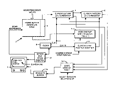
Attention is now directed to Fig. 1 of the
drawings, where there is shown in block diagram form
an embodiment of the present invention suitable to
generate and control a cursor for a bit mapped video
display of otherwise conventional form. The cursor
generation architecture depicted in Fig. 1 creates a
hardware type cursor overlay using a temporary buffer
to store 48 cursor data bits and a column position
counter to synchronize with the frame buffer raster
scan. The full pattern of the cursor is stored in a
non-displayed section of the frame ~uffer at an
address coincidence with the row location within the
video display. Consequently, every row line of the
bit ma~ped display has associated therewith a
corresponding 48 bit long strip of cursor information.
The cursor information is read into the 48
bit temporary buffer from the non-display section of
the frame buffer by raster line during the horizontal
blanking time following the raster scan of the
previous line. As preferably implemented with a dual
port video memory system, the data in the frame buffer
for the next line to be displayed is transferred
during such horizontal blank time to a video display
shift register. Thereafter, during the actual scan of
the buffered line, the clock synchronized transfer of
1 3 ~
video display shift register data to the video display
is selectively modified by logical combinations with
the cursor strip data by action of a counter operated
to identify the beginning and end locations of the
cursor strip within the raster line. This operation
is repeated for each line of displayed frame.
The particularized functional blocks in Fig.
1 can now be referenced to the functional objectives
set forth above in the context of the depicted
preferred embodiment. As shown in Fig. 1, the video
display 1 has a pixel capability of 1024x800. The
characteristics of the pixels are defined by bits
stored in the frame buffer dynamic random access
memory (DRAM) array 2. Memory array 2 is a dual port
video memory having an addressable size greater than
the pixel count of display 1, the non-displayed
portion generally represented by the section 3.
Conceptually, the present invention could be applied
to a bit mapped display system using a single port
video memory. Such implementation would, however, be
somewhat impractical given the limited blank time
available for pattern changes to he introduced by the
computer.
The particular architecture embodied in Fig.
1 includes a pair of 24xl cursor registers 4 and 6, a
conventional 102~xl video display shift register 7, a
master source of clock signals 8, a cursor strip
positioned counter 9, a logic lookup table 14, and
conventional buffer and synchronization and scan
control devices generally depicted as blocks 16 and
17.
Fig. 2 schematically illustrates the spatial
and temporal allocation of the frame buffer for the
present embodiment. Frame buffer 2 is comprised of a
bit mapped video display memory segment which stores
the actual frame pattern for the video display~ as
well an addressable but non-displayed cursor strip
- 7 - ~3~7~
memory segment. Addressing of the cursor strip memory
segment is related by line to the video displayed
memory segment. The availability of such non-
displayed segment of the frame buffer arises, as
commonly known, from the arrangement memory in binary
increments numerically different than the pixel count
of the video display.
The generation of a cursor, such as pointer
18 on video display l, begins with the generation of a
cursor block outline and the further definition of an
internal pattern of the cursor by the computer. The
pattern so defined is loaded into cursor strip memory
segment 3 during the conventional frame buffer writing
operation. The line address of the cursor is matched
to the line location within the video display at which
the cursor is to appear. The column location of the
cursor is defined by a coarse cursor strip positioned
reEerence number which is operable to start at 8 pixel
position increments. As so defined, there exist data
representing a cursor in non-displayed frame buffer
which is aligned by row or line to its intended
location in the video display frame and aligned at 8
plxel increments by column address entered into cursor
strip position counter 9.
At the conclusion o each raster line scan,
during the horizontal blank time, 48 bit long strips
of cursor data for the next succeeding line of the
video display are shifted from frame buffer memory
segment 3 to registers 4 and 6. At the beginning of
the next raster scan cycle, the corresponding line of
video data in the frame buffer is transferred in
conventional manner by row into video display shift
register 7. Consequently, at that time, the data
representing the video pattern for the ne~t succeeding
raster line is resident in video display shift
register 7I the cursor data for the same line is
resident in registers 4 and 6, and data representing
- 8 - ~3~7~
the cursor strip column location resides in position
counter 9. Upon the commencement of the next scan and
synchronous therewith, clock 8 shifts from register 7
the video data by pixel to logic lookup table 14. For
those pi~el positions where no cursor data is to be
superimposed, cursor pattern register 4 and 6 are
disabled by cursor strip position counter 9. Counter
9 is incremented at ~ pixel steps synchronous to clock
8. The clock synchronized raster scan continues
across video display 1 using the data in shift
register 7 until cursor strip position counter 9
identifies the starting location for the cursor data
block. Thereafter, for an interval of 24 pixel
positions, logic lookup table 14 receives not only the `
originally defined video display shift register data
but cursor outline data from register 4 and cursor
pattern data from registe~ 6. The cumulative logic
effects, as defined by the desired boolean
relationship established in block 14, are actually
transmitted to video display 1 through buffer 16.
After such 24 clock cycles, cursor registers 4 and 6
are effectively disabled to return the pattern of
display 1 to that stored in video display shift
register 7 alone. The cycle is~repeated with the
conclusion of the raster line, and the onset of the
horizontal blanking time, with the transfer of 48 bits
of data representin~ the next line of cursor.
Fig. 3 illustrates the generation of an
exemplary cursor, including a cursor outline 19 and a
cursor pattern 21. The rows of the outline and
pattern pixels match the video display, while the
column location is defined by the computer and
identified d~ring the raster scan by the position
counter at intervals of 8 pixels. For instance, in
the context of~ Fig. 8, the cursor outline and resident
internal pattern can start at any column which is a
multiple of 8 pixel positions and will conclude 24
pi~el pO5 i tions
-
~ . : - ~ . -. ,. ~ .
9 13~7~
later. As shown, the outline begins at a pixel
position m and concludes with a position m+24.
Positioning of the cursor pattern 21 within cursor
outline 19 at single pixel increments is performed by
the computer during the generation of the pixel
pattern. For example, as shown at 22, the pattern may
be shifted within the outline during the generation of
the pattern with reference to the outline. Thereby,
the actual pattern of the cursor may be positioned
within the full one pixel precision of the video
display for so long as the line length o the pixel
pattern is 8 pixel positions shorter than the length
of the pixel outline. In the context of Fig. 3, full
column position precision can be retained for a
pattern composed of 16 or fewer pixel columns.
- Increasing the sizes of registers 4 and 6 in
Fig. 1 concurrently increases the new length of the
cursor patterns which can be generated. On the other
hand, such extensions of cursor dimensions do consume
additional area in non-displayed frame buffer segment
3. For the present arrangement the cursor data is
allocated a memory space of 48x800. Such a segment is
well within the reserved of the 131072x8 frame buffer
2, in that the memory associated directly-with the
pixel count of the~video display 1 leaves
approximately 230,000 bits of addressable memory
unused. Note that the defined 48x800 strip of non-
dlsplayed frame buffer allocated to pixel data
consumes appr;oximately 40,000 bits of such residual
memory.
The~use of logic loo~kup table 14 in Fig. 1 to
introduce a boolean relationship into the pattern
actually transmitted to video display 1, based on a
combination of the originally defined video display
pattern, the cursor outline, and the cursor pattern,
provides the user with the ability to overlay the
cursor in a visible form irrespective of the
.
~ 3 ~1 7 ~
background. For instance, a black cursor pattern
placed on a black background would not be visible,
while a black cursor pattern framed within a white
cursor outline and placed against a black background
would be perceivable. An XOR implementation of a
cursor outline is an example of an popular approach to
retaining a cursor pattern irrespective of the
background.
Note as another aspect of the present
invention that the cursor strip of 24 pixels line
length is fully capable of extending in the column
direction from the top of the video display to t~e
very bottom of the video display. Consequently, the
cursor can be configured and logically combined in a
pattern of up to 24x800 pixels dimension. This
provides the use with a great degree of flexibility
when compared to the commonly utilized 16x16 size
cursor blocks, especially given the need for 512 bits
of additional high speed video meMory to implement
even such small cursor patterns.
In the composite, note that the present
invention provides an architecture by which non-
displayed frame buffer can be utilized to store a
relatively elaborate cursor pattecn extending the Eull
height of the screen while using a relatively short
bit length buffer, is implemented to logically
combined cursor data with frame buffer pattern data,
overlays complex frame buffer patterns notwithstanding
the presence o~ windows or scrolling, and provides
these features without unduly burdening the computer
with elaborate software manipulations or transfers of
frame data to temporary store.
It will be understood by those skilled in the
art that the embodiment set forth hereinbefore is
merely exemplary of the various elements and
procedures which are essential to the present
invention, and as such may be replaced by equivalents
, . ~: . . :,,
- :~
~ \
ll - 13~ 7~
without departin~ from the invention thereof, which
now will be defined by the appended claims.