Sélection de la langue

Search

Sommaire du brevet 1317460 

Énoncé de désistement de responsabilité concernant l'information provenant de tiers

Une partie des informations de ce site Web a été fournie par des sources externes. Le gouvernement du Canada n'assume aucune responsabilité concernant la précision, l'actualité ou la fiabilité des informations fournies par les sources externes. Les utilisateurs qui désirent employer cette information devraient consulter directement la source des informations. Le contenu fourni par les sources externes n'est pas assujetti aux exigences sur les langues officielles, la protection des renseignements personnels et l'accessibilité.

Disponibilité de l'Abrégé et des Revendications

L'apparition de différences dans le texte et l'image des Revendications et de l'Abrégé dépend du moment auquel le document est publié. Les textes des Revendications et de l'Abrégé sont affichés :

  • lorsque la demande peut être examinée par le public;
  • lorsque le brevet est émis (délivrance).
(12) Brevet: (11) CA 1317460
(21) Numéro de la demande: 1317460
(54) Titre français: MACHINE DE TIRAGE DE FIBRES OPTIQUES
(54) Titre anglais: OPTICAL FIBER DRAWING APPARATUS
Statut: Périmé et au-delà du délai pour l’annulation
Données bibliographiques
(51) Classification internationale des brevets (CIB):
  • C03B 37/027 (2006.01)
  • B65H 54/88 (2006.01)
  • C03B 37/025 (2006.01)
  • C03B 37/035 (2006.01)
(72) Inventeurs :
  • TSUNEISHI, KATSUYUKI (Japon)
  • ITO, SHIGERU (Japon)
  • YAMAZAKI, TAKASHI (Japon)
(73) Titulaires :
  • SUMITOMO ELECTRIC INDUSTRIES, LTD.
(71) Demandeurs :
(74) Agent: KIRBY EADES GALE BAKER
(74) Co-agent:
(45) Délivré: 1993-05-11
(22) Date de dépôt: 1988-11-22
Licence disponible: S.O.
Cédé au domaine public: S.O.
(25) Langue des documents déposés: Anglais

Traité de coopération en matière de brevets (PCT): Non

(30) Données de priorité de la demande:
Numéro de la demande Pays / territoire Date
177609/1987 (Japon) 1987-11-24

Abrégés

Abrégé anglais


-1-
Abstract:
An optical fiber drawing apparatus includes a furnace
for fusing a forward end of an optical fiber preform for
drawing an optical fiber, and a screening portion for
applying tension to the optical fiber in the line for
testing its strength. The screening portion includes a
suction device disposed along a span of the optical fiber
running through it, for sucking the optical fiber
thereinto in the event of a breakage. The arrangement
avoids broken optical fiber becoming entangled with other
parts of the apparatus and improves productivity.

Revendications

Note : Les revendications sont présentées dans la langue officielle dans laquelle elles ont été soumises.


Claim:
1. An optical fiber drawing apparatus comprising a heating
furnace for fusing a forward end of an optical fiber preform
for drawing an optical fiber therefrom, and a screening
portion including means for applying tension to the optical
fiber in the line for guaranteeing the strength of the fiber,
said screening portion further comprising a suction device
disposed along a passage of the optical fiber running
therethrough for sucking in said optical fiber in the event of
breakage of said optical fiber, said suction device comprising
a suction port provided along the passage, a suction blower
connected to said suction port through a pipe, and a mesh
element provided in the pipe between said suction port and
said suction blower with a pocket formed in said pipe at a
location ahead of the mesh element.

Description

Note : Les descriptions sont présentées dans la langue officielle dans laquelle elles ont été soumises.

1317~60
Optical fiber drawing apparatus
The present invention relates generally to a drawing
arrangment, and, more particularly, to apparatus for
drawing an optical fiber in the manufacture thereof.
Commonly, an optical fiber normally has a tensile
S strength of several hundred kg/mm2 (breaking elongation
at several ~), and, in the longitudinal direction of the
optical fiber, it is necessary to remove any portions
having a low strength, i.e. below 70 kg/mm (breaking
elongation at 1~). For this purpose, it has been the
conventional practice to screen for strength by applying a
constant tension over an entire length of the optical
fiber whereby to break any low strength portions thereof
for removal. In many cases, such a screening process is
incorporated in the apparatus that is arranged to fuse an
optical fiber preform by heating and draw the optical
fiber.
To enable the prior art to be described with the aid
of a diagram, the figures of the drawings will first be
listed.
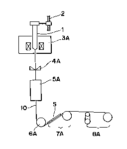
Fig. 1 is a schematic diagram showing the construction
of an optical fiber drawing apparatus according to one
preferred embodiment of the present invention;
Fig. 2 is a schematic diagram showing on an enlarged
scale, the construction of a suction device employed in
the apparatus of Fig. 1: and

- 2 - 1317~60
Fig. 3 is a diagram similar to Fig. 1, which shows a
conventioned optical fiber drawing apparatus.
In the conventional apparatus of Fig. 3, it is
arranged that an optical fiber preform 1 lowered at a
constant speed by a feeding device 2 has its lower end
fused by a furnace 3, whereby to be drawing into an optical
fiber 10. Thereafter, the optical fiber thus formed is
coated with resin by a coating device 4, with subsequent
curing of the resin by a curing furnace 5. It is then
taken up on a capstan 6. The optical fiber 10 is further
passed through a screening portion 7, and subsequently
wound onto a winding machine 8 as a finished optical fiber.
In this known apparatus, however, there is the
disadvantage that, if the optical fiber is broken at a low
strength portion in the screening portion 7, the remainder
of the optical fiber 10 that is continuously drawing out
by the take-up device 6 becomes entangled on said device
6. This requires much time for restoring normal running,
with a consequent loss in productivity.
Accordingly, an essential object of the present
invention is to provide an optical fiber drawing apparatus
that has an improved screening portion free from risk of
entanglement by a broken optical fiber.
Another object of the present invention is to provide
such an apparatus that is simple in construction and
stable in functioning with high reliability.
To these ends, the invention consists of an optical
fiber drawing apparatus comprising a furnace for fusing a
forward end of an optical fiber preform for drawing an
optical fiber therefrom, and a screening portion for
applying tension to the optical fiber in the line for
testing the strength thereof, said screening portion
having a suction device disposed along a span of the
optical fiber running therethrough for sucking said
.~

~ 3 ~ 1317~60
optical fiber thereinto in the event of breakage of said
optical fiber.
Referring now to the drawings, there is shown in Figs.
1 and 2, an optical fiber drawing apparatus according to
S one preferred embodiment of the present invention, which
generally includes a furnace 3A for fusing the forward end
of the optical fiber preform 1 lowered by a feeding device
2 at a constant speed so as to be drawn into an optical
fiber 10; a coating device 4A for coating the drawn
optical fiber with resin; a furnace 5A for curing the
resin on the optical fiber 10; a capstan 6A for taking-up
the optical fiber thus processed; a screening portion 7A
provided with a suction device S, and a winding machine 8A
for winding the finished optical fiber 10 thereonto.
As shown on an enlarged scale in Fig. 2, the suction
device S includes a suction port 11 arranged along a span
of the optical fiber 10; a suction fan 12 connected to
the port 11 through a pipe d; and a mesh element 13 in the
pipe d between the port 11 and the fan 12, with a recess
or pocket 14 being formed within the pipe d at a location
before the mesh element 13.
If the optical fiber 10 is broken in the screening
portion 7A, it is sucked in through the port 11, but is
prevented by the mesh element 13 from reaching the fan 12,
and is collected in the pocket 14.
It is to be noted that, although the fan 12 can be
operated at all times during a drawing operation, it can
be arranged to be operated only at any time when rupture
of the optical fiber in the screening portion 7A, is
detected, for example, by variation of the position of a
dancer roller (not shown) in the winding machine 8A.
According to an experiment carried out by the present
inventors, when an optical fiber was drawn by such
apparatus, it was broken ten times at the screening
portion 7A. The length of optical fiber required for

- ~ _ 4 _ 1317~
restoring the running line was about lOOm on the average.
Meanwhile, as a comparative example, in a case where
an optical fiber was drawn in the conventional apparatus
of Fig. 3, the optical fiber that was broken at the
screening portion 7 became twisted around the capstan 6.
For restoring the running line, a length of optical fiber
of about lOOOm was required on the average in twelve
breakages.
As is clear from the foregoing description, since the
suction device provided in the screening portion sucks in
any broken optical fiber, there is no possibility that such
broken optical fiber will become entangled with other parts
of the apparatus. Thus, restoration of the running line
is simplified, making it possible to improve productivity.
Although the present invention has been fully described
by way of example with reference to the accompanying
drawings, it is to be noted here that various changes and
modifications will be apparent to those skilled in the art.
Therefore, unless otherwise such changes and modifications
depart from the scope of the present invention, they should
be construed as included therein.
~,'
., 1,

Dessin représentatif
Une figure unique qui représente un dessin illustrant l'invention.
États administratifs

2024-08-01 : Dans le cadre de la transition vers les Brevets de nouvelle génération (BNG), la base de données sur les brevets canadiens (BDBC) contient désormais un Historique d'événement plus détaillé, qui reproduit le Journal des événements de notre nouvelle solution interne.

Veuillez noter que les événements débutant par « Inactive : » se réfèrent à des événements qui ne sont plus utilisés dans notre nouvelle solution interne.

Pour une meilleure compréhension de l'état de la demande ou brevet qui figure sur cette page, la rubrique Mise en garde , et les descriptions de Brevet , Historique d'événement , Taxes périodiques et Historique des paiements devraient être consultées.

Historique d'événement

Description Date
Inactive : CIB de MCD 2006-03-11
Le délai pour l'annulation est expiré 1999-05-11
Lettre envoyée 1998-05-11
Accordé par délivrance 1993-05-11

Historique d'abandonnement

Il n'y a pas d'historique d'abandonnement

Titulaires au dossier

Les titulaires actuels et antérieures au dossier sont affichés en ordre alphabétique.

Titulaires actuels au dossier
SUMITOMO ELECTRIC INDUSTRIES, LTD.
Titulaires antérieures au dossier
KATSUYUKI TSUNEISHI
SHIGERU ITO
TAKASHI YAMAZAKI
Les propriétaires antérieurs qui ne figurent pas dans la liste des « Propriétaires au dossier » apparaîtront dans d'autres documents au dossier.
Documents

Pour visionner les fichiers sélectionnés, entrer le code reCAPTCHA :


Pour visualiser une image, cliquer sur un lien dans la colonne description du document. Pour télécharger l'image (les images), cliquer l'une ou plusieurs cases à cocher dans la première colonne et ensuite cliquer sur le bouton "Télécharger sélection en format PDF (archive Zip)" ou le bouton "Télécharger sélection (en un fichier PDF fusionné)".

Liste des documents de brevet publiés et non publiés sur la BDBC .

Si vous avez des difficultés à accéder au contenu, veuillez communiquer avec le Centre de services à la clientèle au 1-866-997-1936, ou envoyer un courriel au Centre de service à la clientèle de l'OPIC.


Description du
Document 
Date
(aaaa-mm-jj) 
Nombre de pages   Taille de l'image (Ko) 
Abrégé 1993-11-15 1 14
Page couverture 1993-11-15 1 11
Revendications 1993-11-15 1 19
Dessins 1993-11-15 2 15
Description 1993-11-15 4 133
Dessin représentatif 2001-12-27 1 4
Avis concernant la taxe de maintien 1998-06-08 1 177
Taxes 1997-04-17 1 64
Taxes 1996-04-17 1 68
Taxes 1995-04-21 1 64
Correspondance de la poursuite 1991-05-28 1 36
Demande de l'examinateur 1991-03-25 1 32
Correspondance de la poursuite 1989-03-21 1 31
Correspondance reliée au PCT 1993-02-15 1 50