Sélection de la langue

Search

Sommaire du brevet 1317925 

Énoncé de désistement de responsabilité concernant l'information provenant de tiers

Une partie des informations de ce site Web a été fournie par des sources externes. Le gouvernement du Canada n'assume aucune responsabilité concernant la précision, l'actualité ou la fiabilité des informations fournies par les sources externes. Les utilisateurs qui désirent employer cette information devraient consulter directement la source des informations. Le contenu fourni par les sources externes n'est pas assujetti aux exigences sur les langues officielles, la protection des renseignements personnels et l'accessibilité.

Disponibilité de l'Abrégé et des Revendications

L'apparition de différences dans le texte et l'image des Revendications et de l'Abrégé dépend du moment auquel le document est publié. Les textes des Revendications et de l'Abrégé sont affichés :

  • lorsque la demande peut être examinée par le public;
  • lorsque le brevet est émis (délivrance).
(12) Brevet: (11) CA 1317925
(21) Numéro de la demande: 1317925
(54) Titre français: EMBASSE POUR INSTRUMENT
(54) Titre anglais: INSTRUMENT SUPPORT SOCKET
Statut: Périmé et au-delà du délai pour l’annulation
Données bibliographiques
(51) Classification internationale des brevets (CIB):
  • F16M 11/04 (2006.01)
(72) Inventeurs :
  • JOHNSON, JOEL W. (Etats-Unis d'Amérique)
(73) Titulaires :
  • Q-CO INDUSTRIES, INC.
  • O'CONNOR ENGINEERING LABORATORIES
(71) Demandeurs :
  • Q-CO INDUSTRIES, INC. (Etats-Unis d'Amérique)
  • O'CONNOR ENGINEERING LABORATORIES
(74) Agent: MACRAE & CO.
(74) Co-agent:
(45) Délivré: 1993-05-18
(22) Date de dépôt: 1988-07-26
Licence disponible: S.O.
Cédé au domaine public: S.O.
(25) Langue des documents déposés: Anglais

Traité de coopération en matière de brevets (PCT): Non

(30) Données de priorité de la demande: S.O.

Abrégés

Abrégé anglais


Abstract
An instrument support socket for adjustably
receiving a member of a support plate having an outer
spherical surface wherein the socket, formed
integrally, is an outer and upper ring portion
connected to an inner and lower ring portion by
intercrossed ribs with upper surfaces of the ring
portions and ribs defining segments of a conical
surface capable of cooperating with spherical
surfaces of differing radii. The socket forms a
tripod head by having lugs on the upper ring portion
that extend out and embrace the elements of the
tripod legs so that the tripod legs are mounted from
the outside of their respective elements.

Revendications

Note : Les revendications sont présentées dans la langue officielle dans laquelle elles ont été soumises.


-6-
I claim as my invention:
1. An instrument support socket for receiving,
and locking with, elements defining an external
spherical surface, comprising, an outer and upper
ring portion, an inner and lower ring portion, and a
plurality of ribs interconnecting said ring portions,
the upper surfaces of said ring portions and said
ribs defining segments of an annular upwardly opening
internal conical surface capable of receiving
spherical surfaces having a range of radii.
2. The socket of claim 1 in which said ribs are
intercrossed and in planes parallel to the axes of
said ring portions, said ring portions and said ribs
being formed as one integral piece.
3. The socket of claim 1 in which said outer
and upper ring is formed with three tripod leg lugs,
each of said lugs having portions facing the other
two lugs with said portions being adapted to receive
tripod leg elements, and means for securing tripod
leg elements between said facing lug portions.
4. The combination of claim 3 in which said
lugs are formed with tiedown holes located between
adjacent ones of said tripod legs.
10-102/mjc

Description

Note : Les descriptions sont présentées dans la langue officielle dans laquelle elles ont été soumises.

-2- 13~7~2~
Background
This invention generally relates to instrument
support structures such as tripod heads, and more
particularly concerns a universal type leveling
socket for such structures.
In United States patent ~o. g,019,710, issued
April 26, 1977, an instrument support socket is
disclosed and claimed that includes a support plate
with a plurality of feet whose outer surfaces define
segments oE an annular surface that is a section of
an external spherical surface. That spherical
surface fits into a ring with a mating annular
internal spherical surface. The plate can rock in
the ring and, when the surfaces are drawn tightly
together, the plate is firmly locked relative to the
ring in the position desired.
In the commercial embodiment of this device, the
radius of the spherical surfaces defined by the ring
and the feet of the mounting plate was 3-1/2 lnches.
Similar competitive devices have appeared in which
the support plate external spherical surfaces are of
different radii, such as 50 millimeters (about Z
inches) and 75 millimeters (about 3 inches). A
differing size plate does not mesh and lock well with
the spherical ring configuration shown in the patent
just referred toO
Accordingly, it is an object of the invention to
provide a support socket of the type discussed which
receives and locks well with a wide variety oE
mounting plate external spherical locking
configurations~
Another object is to provide a support socket of
the foregoing kind which is both lightweight and
strong~ and whicht because of its construction,
10-102/mjc
,. . . .
.

_3_ 131 ~2~
provides multiple locking edges for engagement with a
mounting plate.
It is also an object to provide a support socket
as characterized above that is an lntegral part oE a
tripod head that, for added rigidity, mounts the
tripod legs from the outside of the leg elements.
Summary
The support socket is an annular structure
having ribs connecting an outer and upper ring
portion with an inner and lower ring portion. The
upper surface of the ring portions and the ribs
define segments of an upwardly opening conical
surface capable of receiving spherical mounting plate
portions having a wide range of radii.
Tripod leg lugs are formed on the outer and
upper ring portion of the support socket so that the
lugs embrace and connect to the outer sides of the
leg elements. Tiedown holes are formed in the lugs
so that they are positioned between adjacent ones of
the tripod legs.
Drawings
Other objects and advantages of the invention
will become apparent upon reading the following
detailed description and upon reEerence to the
drawings, in which:
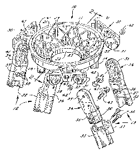
Figure 1 is a fragmentary perspective, partially
broken away, of a support socket embodying the
invention shown connected to the upper portions of
three tripod legs; and
Fig. 2 is a slightly enlarged section of the
support socket taken along the linP 2-2 in Fig. 1.
Description
While the invention will be described in
connection with a preferred embodimentr it will be
understood that I do not intend to limit the
10-102/mjc
.
- , ,' . :
:

3~7~2~
invention to that embodiment. On the contrary, I
intend to cover all alternatives, modifications and
equivalents as may be included within the spirit and
scope of the invention as defined by the appended
claims.
Turning to the drawings, there is shown an
instrument support socket 10 haviny an upwardly
opening annular surEace 11 adapted to receive
instrument support plates with external spherical
surfaces such as that shown in said U.S. patent No.
4,019,710. In the preEerred embodiment, the socket
10 is mounted on a set of three tripod legs 12, 13
and 14 and it therefore forms a tripod head.
In accordance with the invention, the socket 10
is formed of an outer and upper ring portion 21 and
an inner and lower ring portion 22 which are
connected by ribs 23 with the upper surfaces of the
ring portions 21, 22 and ribs 23 forming the upwardly
opening annular sur~ace 11 as segments of an internal
conical surface. An external spherical surface will
therefore fit into the surface 11 with circular line
contact against the upper surfaces of the ribs 23.
Preferably, the ribs 23 are intercrossed and disposed
in planes parallel to the vertical central axes of
the ring portions 21, 22, and in the illustrated
embodiment, the unit is formed as a single integral
piece.
I'he ribs 23 not only constitute a rigid,
lightweight structure, but also define a plurality of
edges in the conical sur~ace 11 to grip a spherical
member drawn tightly into the socket. The central
openin~ and the lower ring portion 22 provides
clearance for a locking knob to interconnect with a
mounting plate so as to draw the mounting plate
spherical portion tightl~ against the segmented
lQ-102/mjc
, . ~ ,
:

~3~ ~92~
surface 11 -- see said patent No. 4,019,710. The
openness of the ring portions 21, 22 and the open
areas between the ribs 23 allows foreign material to
fall freely through the socket 10 and not accumulate
and thus interfere with the Eirm mounting of a plate
in the socket. It would also be apparent that a
mounting plate with a spherical surface positioned
within the socket can be tilted freely so as to
achieve any desired orientation.
To mount the socket 10 on the tripod legs 12-14,
lugs 30 are formed on the upper ring portion 21 with
each lug 30 having portions 31 facing the other two
lugs, with the portions 31 defining mounting surfaces
having central holes 32 adapted to receive elements
of the tripod legs. The tripod legs 12-14 include
leg elements defined by extruded members 33 receiving
end pieces 34 with flanges 35 fitting against and
between the surfaces 31 of adjacent lugs 30, and
tongues 36 that fit down into the ends of the
extrusions 33. The end pieces 34 are secured to the
extrusions 33 by blocks 37 and screws 3~. The lug
elements 30 are secured to the leg element end pieces
34 by bolts 41, nuts 42 and washers 43.
By mounting the tripod legs from the outside of
the spaced leg elements, a wider more rigid
connection is obtained between the legs 12-14 and the
socket 10. This also permits tiedown holes 45 to be
formed in the lugs 30 between adjacent legs. Such
tiedown lugs are often used to firmly tie a tripod to
an underlying supporting surface and having the
tiedown holes 45 outside of the tripod legs makes
them more accessible and therefore easier to tie down
the tripod.
10-102/mjc
' ' , ,

Dessin représentatif
Une figure unique qui représente un dessin illustrant l'invention.
États administratifs

2024-08-01 : Dans le cadre de la transition vers les Brevets de nouvelle génération (BNG), la base de données sur les brevets canadiens (BDBC) contient désormais un Historique d'événement plus détaillé, qui reproduit le Journal des événements de notre nouvelle solution interne.

Veuillez noter que les événements débutant par « Inactive : » se réfèrent à des événements qui ne sont plus utilisés dans notre nouvelle solution interne.

Pour une meilleure compréhension de l'état de la demande ou brevet qui figure sur cette page, la rubrique Mise en garde , et les descriptions de Brevet , Historique d'événement , Taxes périodiques et Historique des paiements devraient être consultées.

Historique d'événement

Description Date
Inactive : Demande ad hoc documentée 1996-05-18
Le délai pour l'annulation est expiré 1995-11-20
Lettre envoyée 1995-05-18
Accordé par délivrance 1993-05-18

Historique d'abandonnement

Il n'y a pas d'historique d'abandonnement

Titulaires au dossier

Les titulaires actuels et antérieures au dossier sont affichés en ordre alphabétique.

Titulaires actuels au dossier
Q-CO INDUSTRIES, INC.
O'CONNOR ENGINEERING LABORATORIES
Titulaires antérieures au dossier
JOEL W. JOHNSON
Les propriétaires antérieurs qui ne figurent pas dans la liste des « Propriétaires au dossier » apparaîtront dans d'autres documents au dossier.
Documents

Pour visionner les fichiers sélectionnés, entrer le code reCAPTCHA :


Pour visualiser une image, cliquer sur un lien dans la colonne description du document. Pour télécharger l'image (les images), cliquer l'une ou plusieurs cases à cocher dans la première colonne et ensuite cliquer sur le bouton "Télécharger sélection en format PDF (archive Zip)" ou le bouton "Télécharger sélection (en un fichier PDF fusionné)".

Liste des documents de brevet publiés et non publiés sur la BDBC .

Si vous avez des difficultés à accéder au contenu, veuillez communiquer avec le Centre de services à la clientèle au 1-866-997-1936, ou envoyer un courriel au Centre de service à la clientèle de l'OPIC.


Description du
Document 
Date
(aaaa-mm-jj) 
Nombre de pages   Taille de l'image (Ko) 
Page couverture 1993-11-30 1 14
Abrégé 1993-11-30 1 16
Revendications 1993-11-30 1 26
Dessins 1993-11-30 1 54
Description 1993-11-30 4 149
Dessin représentatif 2001-08-01 1 29
Correspondance reliée au PCT 1992-08-18 1 23
Correspondance de la poursuite 1991-04-12 2 44
Demande de l'examinateur 1991-01-07 1 43
Courtoisie - Lettre du bureau 1992-11-17 1 20