Sélection de la langue

Search

Sommaire du brevet 1318083 

Énoncé de désistement de responsabilité concernant l'information provenant de tiers

Une partie des informations de ce site Web a été fournie par des sources externes. Le gouvernement du Canada n'assume aucune responsabilité concernant la précision, l'actualité ou la fiabilité des informations fournies par les sources externes. Les utilisateurs qui désirent employer cette information devraient consulter directement la source des informations. Le contenu fourni par les sources externes n'est pas assujetti aux exigences sur les langues officielles, la protection des renseignements personnels et l'accessibilité.

Disponibilité de l'Abrégé et des Revendications

L'apparition de différences dans le texte et l'image des Revendications et de l'Abrégé dépend du moment auquel le document est publié. Les textes des Revendications et de l'Abrégé sont affichés :

  • lorsque la demande peut être examinée par le public;
  • lorsque le brevet est émis (délivrance).
(12) Brevet: (11) CA 1318083
(21) Numéro de la demande: 1318083
(54) Titre français: CHARNIERE SERVANT A FIXER DES COUVERCLES SUR DES APPAREILS SANITAIRES TELS DES W.-C., AVEC DISPOSITIF DE REGLAGE
(54) Titre anglais: HINGE FOR ATTACHING COVERING ELEMENTS TO SANITARY FITTINGS, SUCH AS SEAT/COVER ASSEMBLIES FOR TOILETS, WITH ADJUSTMENT DEVICE
Statut: Périmé et au-delà du délai pour l’annulation
Données bibliographiques
(51) Classification internationale des brevets (CIB):
  • A47K 3/12 (2006.01)
  • A47K 13/12 (2006.01)
  • E05D 7/04 (2006.01)
(72) Inventeurs :
  • FAIT, CLAUDIO (Italie)
(73) Titulaires :
  • AMERICAN STANDARD INC.
(71) Demandeurs :
  • AMERICAN STANDARD INC. (Etats-Unis d'Amérique)
(74) Agent: SMART & BIGGAR LP
(74) Co-agent:
(45) Délivré: 1993-05-25
(22) Date de dépôt: 1989-05-01
Licence disponible: S.O.
Cédé au domaine public: S.O.
(25) Langue des documents déposés: Anglais

Traité de coopération en matière de brevets (PCT): Non

(30) Données de priorité de la demande:
Numéro de la demande Pays / territoire Date
34,852 B/88 (Italie) 1988-06-08

Abrégés

Abrégé anglais


Abstract: The hinge has a fixed element (5) to be fastened to a hole
provided in the rear part of a sanitary fitting, and a
movable element hinged to the fixed element,to be secured
to the seat or cover, with the movable element consisting
of a bar (11) adjustable within a box-shaped housing in the
cover, and of means to immobilize the said bar in the said
housing in the desired position.
The locking means are a transverse stud screwed into a
hole in the cover.

Revendications

Note : Les revendications sont présentées dans la langue officielle dans laquelle elles ont été soumises.


THE EMBODIMENTS OF THE INVENTION IN WHICH AN EXCLUSIVE
PROPERTY OR PRIVILEGE IS CLAIMED ARE DEFINED AS FOLLOWS:
1. An adjustable hinge assembly adapted to be fastened
to a sanitary fixture, such as a bidet or a toilet, said hinge
assembly comprising:
a fixed hinge element to be mounted on the upper
rear flat region of said fixture, and an articulating hinge
element mounted to said fixed hinge element;
said articulating hinge element having an elongated
bar, one end of which is pivotally mounted to said fixed
hinge, the other end being insertable into a correspondingly
shaped well-like chamber formed in a seat and/or cover for
said fixture; and
means formed on said elongated bar to cooperate with
a latch member adapted to be transversely mounted on said seat
and/or cover to releasably and adjustably fix said articulat-
ing member at a desired insertion depth in said well-like
chamber so that the front section of the seat and/or cover
match the peripheral profile of the front upper rim of said
fixture whereby said seat and/or cover can be adjusted with
respect to said fixture and can be interchanged with a like
seat and/or cover.
2. The adjustable hinge assembly of claim 1 wherein
said elongated bar is rectangular and its elongated lower
surface is toothed so that when the latch member is
transversely mounted on said seat and/or cover, said elongated
bar is fixed in its desired position.
3. The adjustable hinge assembly of claim 1 further
comprising a tubular metal member adapted to slidingly receive
said elongated bar to form a sliding fit therewith, said
tubular metal member being insertable into said corresponding-
ly shaped well like chamber formed in said s at and/or said
cover.
4. The adjustable hinge of claim 3 wherein said tubular
member is rectangular.

5. The adjustable hinge of claim 3 further includes a
threaded sleeve adapted to be inserted transversely of said
seat and/or cover so that one end engages said tubular member.
6. The adjustable hinge of claim 4 wherein a headless
threaded stud threads into said thread sleeve, the forward end
of which latches said elongated bar in fixed position.
7. In combination, an adjustable hinge assembly adapted
to be fastened to a sanitary fixture, such as a bidet or
toilet, and a seat and/or cover pivotally mounted thereto;
said hinge assembly adapted to be mounted to the flat rear
region of said fixture and an articulating hinge element, one
end of which is pivotally mounted to said fixed hinge element,
and the other end of which is adjustably mounted to said seat
and/or cover; said articulating hinge element having an
elongated bar, one end of which is adjustably insertable into
a correspondingly shaped well-like chamber formed in said seat
and/or cover for said fixture; and means formed on said
elongated bar which cooperates with a latch member
transversely mounted on said seat and/or cover to releasably
and adjustably fix said articulating member at a desired
insertion depth in said well-like chamber so that the front
section of the seat and/or cover match the peripheral profile
of the front upper rim of said fixture whereby said seat
and/or cover can be adjusted with respect to said fixture and
can be interchanged with a like seat and/or cover.

Description

Note : Les descriptions sont présentées dans la langue officielle dans laquelle elles ont été soumises.

~~ This invention concerns a hinge capable of allowing
adjustment of the position of covering elements with respect
to their corresponding sanitary fittings, such as toilets or
bidets.
In particular, the invention is suitable for the attach-
ment of seat/cover assemblies to toilets in general.
It is known that the latt:er are produced by casting
inside suitable multi-part molds, which consists of a material
permeable to liquids. It is also known that a certain number
of castings c~n be made with a single mold, and that between
one casting and another, the shaping cavity of the mold is
subject to a small but continuolls dimensional change. More
specifically, the cavity enlarges, by as much as several
millimetres over the service life of a mold, with the result
that the toilet bowls are dimensionally different, especially
if the first ones cast in a particular mold are compared with
the last ones cast.
On the other hand, the seat/cover assemblies designed to
be fastened subsequently to the toilets have unvarying
~0 dimensions, since they are made of molded synthetic materials.
In short, it can happen that the said assemblies, when
installed on their respective toilets, quite often do not
match the outer peripheral profile of the upper rim of the
toilet as well as desired. In particular, the front edge of
the seat is farther back than the corresponding rim of the
toilet, creating a discontinuity or step. This is not only
annoying to users, but disadvantageous from an aesthetic
standpoint.
Moreover, the usual hinge devices used to fasten the said
seatjcover assemblies offer no opportunity to intervene in any
way to prevent this.
The principal object of this invention is to make
available a hinge capable of eliminating the disadvantages
presented above in the context of a simple and rational design
solution.
According to the invention, there is provided in combina-
tion an adjustable hinge assembly adapted to be fastened to a
_~
,~

13~8083
sanitary fixture, such as a bidet or toilet, and a seat and/or
cover pivotally mounted thereto; said hinge assembly adapted
to be mounted to the flat rear region of said fixture and an
articulating hinge element, one end of which is pivotally
mounted to said fixed hinge element, and the other end of
which is adjustably mounted to said seat and/or cover, said
articulating hinge element having an elongated bar, one end of
which is adjustably insertable into a correspondingly shaped
well-like chamber formed in said seat and/or cover for said
fixture; and means formed on said elongated bar which cooper-
ates with a latch member transversely mounted on said seat
and/or cover to releasably and acljustably fix said articulat-
ing member at a desired insert:ion depth in said well-like
chamber so that the front section of the seat and/or cover
match the peripheral profile of the front upper rim of said
fixture whereby said seat and/or cover can be adjusted with
respect to said fixture and can be interchanged with a like
seat and/or cover. The said bar is preferably equipped, on
its own lower surface, with
- la -

~3~0~3
a toothed rack with ver~ closely spaced interstices, which are
capable of accommodating the end of the said latch member to
immobilize the cover and/or seat at the desired insertion
depth.
Thanks to these means, it is possible to adjust the
covering element or seat with respect to the corresponding
fitting or toilet, and thus to eliminate the aforesaid
problems.
These and other merits and characteristics of the
invention will become evident from the detailed description
which follows, given with reference to the attached Figures,
in which:
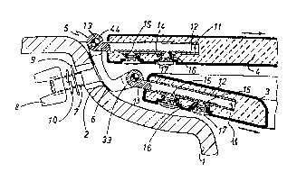
Figure 1 shows, at enlarged scale, the section I-I
indicated in Figure 3;
Figure 2 shows, at enlarged scale, the movable hinge
element that is at the top of Figure l;
Figure 3 is a top view of Figure 1, at reduced scale.
The aforesaid Figures (see especially Figure 1)
illustrate a toilet ~1), which has been shown only partially
since the characterizing elements o~ the invention are well
suited for toilets of any configuration and dimensions, and
for other sanitary fittings such as bidets.
As is usual, two through holes (2) are present at the
rear region of the toilet (1), placed symmetrically with
respect to the vertical plane of symmetry of the said toilet
(1). Each individual hole (2) is designed for fastening a
pair of hinges forming part of a single element to
support/articulate a seat (3) and a cover (4), which are shown
only in part. In the instance illustrated, the hinge is of
the type equipped with two distinct articulation axes for the
said seat and cover, but there is no reason why the latter
could not, for example, pivot about a common axis, as is well
known to persons skilled in the art.
Returned to Figure 1, we see a fixed hinge element (5)
which is shaped so as to rest on the toilet (1) with inter-
position of a suitable gaskat (6), and from which arises a
rear threaded pin (7) which is threaded into the said hole
(2). Moreover, immobilization of this element ~5) is
-- 2 --
.
. .,~

~ 3 ~ 8 3
entrusted to a wing nut (8), with interposition of a washer
(9) and lock washer (10).
The same element (see also Figure 3) has two superimposed
pairs of opposed fixed knuckles, between which is inserted the
movable element of the hinge, consisting of the bar (11) with
knuckle (13), the latter capable of being aligned with the
fixed knuckles to accommodate the articulation pin (44) or
(33~ of the cover (4) and seat (3), respectively. The movable
hinge element of both the seat (3) and the cover (4) consists
of a bar (11) or strip which fits essentially exactly into a
box-shaped metal element (12) of matching shape which is
embedded in the seat (3) and cover (4) respectively. The box-
shaped element (12) runs longitudinally with respect to the
latter, and opens at their rear edge, where the bar (11) can
be inserted (see Figure 3). As illustrated in Figure 2, there
is present on the lower surface of the bar (11) a rack (14)
with triangular teeth, the interstices of which are capable of
accommodating tha pointed ends of the two immobilization and
adjustment screws (15)~
In the instance illustrated, the said screws (15) consist
of headless screws or set screws, with hexagonal socket heads
(Figure 2). The said screws (15) are screwed into respective
threaded sleeves (16) fastened to the box-shaped element (lZ)
and located on the lower surface of the cover (4) or seat (3)
(Figure 1). Lastly, referring back to Figure 2, note that the
said screws are concealed by respective press-in caps (17),
preferably having the same color as elements (3) and (4).
The merits and advantages of the invention are clearly
understandable from the above and from an examination of the
attached Figures.
~7;
. . . "

Dessin représentatif
Une figure unique qui représente un dessin illustrant l'invention.
États administratifs

2024-08-01 : Dans le cadre de la transition vers les Brevets de nouvelle génération (BNG), la base de données sur les brevets canadiens (BDBC) contient désormais un Historique d'événement plus détaillé, qui reproduit le Journal des événements de notre nouvelle solution interne.

Veuillez noter que les événements débutant par « Inactive : » se réfèrent à des événements qui ne sont plus utilisés dans notre nouvelle solution interne.

Pour une meilleure compréhension de l'état de la demande ou brevet qui figure sur cette page, la rubrique Mise en garde , et les descriptions de Brevet , Historique d'événement , Taxes périodiques et Historique des paiements devraient être consultées.

Historique d'événement

Description Date
Inactive : CIB de MCD 2006-03-11
Le délai pour l'annulation est expiré 1998-05-25
Lettre envoyée 1997-05-26
Accordé par délivrance 1993-05-25

Historique d'abandonnement

Il n'y a pas d'historique d'abandonnement

Titulaires au dossier

Les titulaires actuels et antérieures au dossier sont affichés en ordre alphabétique.

Titulaires actuels au dossier
AMERICAN STANDARD INC.
Titulaires antérieures au dossier
CLAUDIO FAIT
Les propriétaires antérieurs qui ne figurent pas dans la liste des « Propriétaires au dossier » apparaîtront dans d'autres documents au dossier.
Documents

Pour visionner les fichiers sélectionnés, entrer le code reCAPTCHA :


Pour visualiser une image, cliquer sur un lien dans la colonne description du document. Pour télécharger l'image (les images), cliquer l'une ou plusieurs cases à cocher dans la première colonne et ensuite cliquer sur le bouton "Télécharger sélection en format PDF (archive Zip)" ou le bouton "Télécharger sélection (en un fichier PDF fusionné)".

Liste des documents de brevet publiés et non publiés sur la BDBC .

Si vous avez des difficultés à accéder au contenu, veuillez communiquer avec le Centre de services à la clientèle au 1-866-997-1936, ou envoyer un courriel au Centre de service à la clientèle de l'OPIC.


Description du
Document 
Date
(aaaa-mm-jj) 
Nombre de pages   Taille de l'image (Ko) 
Revendications 1993-11-17 2 78
Abrégé 1993-11-17 1 10
Page couverture 1993-11-17 1 13
Dessins 1993-11-17 1 37
Description 1993-11-17 4 156
Dessin représentatif 2000-08-15 1 16
Avis concernant la taxe de maintien 1997-08-18 1 179
Taxes 1995-04-12 1 43
Taxes 1996-04-16 1 41
Correspondance reliée au PCT 1993-03-12 1 33
Correspondance de la poursuite 1991-08-27 2 54
Demande de l'examinateur 1991-02-27 1 69