Note : Les descriptions sont présentées dans la langue officielle dans laquelle elles ont été soumises.
~18~2
TTR25
INSITU ENER5Y BEAM PROCESSING OF R~ILROAD
TRACK AND EQUIPMENT FOR INCREASING SERVICE LIFETIME
This invention relates generally to the surface
hardening and/or refurbishing ln tu of railroad
equipment such as rail tops and side surfaces, rail
splitters, rolling stock wheels, and other surfaces
subject to operational wear in the general rail
transport industry. More particularly, this invention
provides a method and apparatus for accomplishing such
surface hardening and/or refurbishing by the use of a
laser, or out-of-vacuum electron beam.
BACKGROUND OF THIS INVENTION
Because of the very high surface loading and
frequency of application of concomitant stresses in
railroad equipment such as rails, buggy and train
wheels, switch gear and the like, as well as the
difficulty of effectively utilizing lubrication, such
equipment is often prone to very rapid wear and/or
microcrack damage.
; As an example, in regions of very high traffic or
; sharp curves it is not uncommon to have to replace rails
at intervals as short as 6 months. An even worse wear
condition is sometimes found with the steel wheels of
the train engines and other heavily loaded rolling
stock, such as in the case of unit trains. As a result
of this situation it has been estimated that the cost of
rail repair and replacement in North America amounts to
over 2 billion dollars annually.
Because of this persistent wear problem and the
associated very great expense and interruption of
service imposed by component replacement, a few recently
constructed rail tracks have been built with special
wear resistant rails. This procedure, which involves
the manufacture of rails of a high grade steel and
subsequent case hardening, has been found to be very
effective in reducing track wear or microcrack damage,
such that the useful life of a particular track may be
extended by as much as 5 times.
2 i ~ ~3~
Vnfortunately however, this solution is very
expensive, both in terms of the extra cost of the higher
quality steel and the cost of the induction hardening
process and equipment necessary, not to mention the very
high labour costs involved in rail replacement.
GENER~L DESCRIPI'ION 0~ ~'HIS INVENTION
It is an aim of an aspect of this invention to
increase the wear and microcrack resistance of track and
rolling equipment and thereby extend their useful
lifetimes, by an in situ surface hardening, alloying or
cladding process, which utilizes a high power CW carbon
dioxide laser, or out-of-vacuum electron bea~.
In a general way, the aim is to increase the
serviceable lifetime of railway track and rolling
equipment. The surface processing aspect of the
invention involves a rapid heating and/or melting of the
rail surface, or near-surface bulk material, by an
intense energy beam, followed by an equally rapid self-
quenching or forced cooling. Thus there are created
localized regions within the rail head which are not
only highly resistant to normal frictional wear but also
to microcrack damage. The increased operational
lifetime arises due to an enhanced resistance to
abrasive wear, and also to surface damage due to flaking
or shelling~
More specifically, the invention involves the
heat-treatment and/or alloying of a narrow but
relatively deep, typically elliptically shaped strip or
channel region at an appropriate area on the rail head
profile, to act both as an abrasion resistant load-
bearing surface and as a barrier for microcrack
propagation.
With regard to fatigue-generated microcracks, these
are found to propagate rapidly in the horizontal plane
near the rail cap surface (mode #1 propagation), due to
lubrication contamination. sy providing a very hard
heat-treated vertical barrier at the appropriate
position, it is possible to significantly arrest this
3 1 3 ~
type of mode ~1 microcrack propagation, or at least
convert it into a less serious mode #2 category.
Another use of the present invention is in the
repair of rail surfaces already severely damaged by
microcracks, through the mechanism of melting and
resolidification of the affected area. In this manner,
rail head sections which have previously developed
serious cracks but have not yet spalled or shelled
significantly, could conceivably be leffectively
rejuvenated by allowing an intense b~eam to remelt the
cracked area~ In such cases it may also be beneficial
to add a small amount of alloy "filler material",
possibly in the form of a feed wire, so as to provide an
even better abrasive and microcrack resistance.
In order to increase the process speed
significantly, it would be possible to use a laser beam
with plasma or arc "augmentation", such that additional
electrical energy could be conveyed directly into the
keyhole (created by the beam) via the ionization path
provided by the laser radiation. In this manner, a
factor of four times or more in process speed should be
achievable, without the need for a larger laser device.
In principle it should also be possible to utilize an
intense out-of-vacuum electron beam to provide the
"keyhole" energy deposition required for the process.
In areas where significant surface material loss
has already occurred due to flaking or shelling, it
would likewise be possible to reclaim the rail by
replacing the lost surface material by an ln situ laser
cladding process, also forming an aspect of this
invention. In such instances the rail head would most
probably have to be "finish ground" to the final optimum
dimensions. In this connection, profile rail grinding
- machines are already well established in the rail
transport industry.
THE RAIL-WHEEL INTERFACE PROBLEM
_
The deterioration of railroad rail and wheel
surfaces (the rail-wheel interface problem) is generally
characterized by two mechanisms of material removal.
4 13~3~2
These occur at the wheel and rail contact points. The
two processes are:
1. Microscopic material loss due to friction
generated abrasion.
2. Macroscopic material loss due to flakiny,
spalling or shelling.
The first mechanism, friction generated abrasion,
results in a gradual loss of surface material
predomlnantly on the wheel flanges and inside surfaces
of the "high rail"; particularly on curves~ This type
of frictional wear can result in very rapid rail and
wheel deterioration if lubrication is not present~ This
aspect has now become particularly troublesome with the
ever increasing appearance of heavily loaded unit
trains.
This being the case, automatic flange-lubricators
are increasingly being installed on railroad lines,
particularly before sharp curves. Lubrication of the
wheel flange and inside rail surface has resulted in an
extension of the useful lifetime of these items by as
much as a factor of 3. An additional but equally
; important side benefit that has been realized by rail
lubrication is a near 30% reduction in fuel costs for
the prime mover. Consequently, rail lubrication is
rapidly becoming a universally accepted procedure.
However, the second type of material removal,
generally categorized by descriptive terms such as
dandruff, flaking, spalling and shelling, can be a much
more rapid and debilitating process (once it has
started) , since unlike the case of microscopic abrasive
wear, relativaly large particles of material are
dislodged.
The term dandruff is characterized by the
generation of small particles, typically less than 1 or
2 square mm in area and perhaps a maximum of 0.1 mm
thick. In flaking, the particle size ranges up to abou-t
1 or 2 square cm in area and up to 1 mm in -thickness.
Spalling and shelling usually refer to the generation
and loss o~ surface particulates that are larger still.
~3~3~2
As might be expected, this second type of material
loss can be very detrimental to rail service, since once
it has started it progresses very rapidly. This follows
as a consequence of the large nonuniformity created in
the rail-wheel contact surface by the loss of a flake.
The condition results in impact loading of the members,
accompanied by a further acceleration in the phenomenon.
The generation of "corrugations" is often a subsequent
symptomatic feature of this flaking deterioration
process. These phenomena generally affect both wheel
and rail members with equal severity.
In certain instances, microcracks can propagate
lar~e distances in the horizontal plane and then
suddenly execute a 90 turn into the bulk material.
Such a phenomenon can quickly lead to very deep vertical
cracks developing into the bulk rail member. This
process, commonly known as a "squat", can if undetected
and repaired subsequently lead to a very serious
complete transverse break in the rail track.
As of the present time there has been no effective
in situ remedy for these flaking, shelling or squat
processes, other than to grind off the top of the rail
head and wheel surfaces to a considerable depth. In
many cases companion microcracks propagate deep within
the bulk material and the items must then be replaced.
Experiment has shown that the reason for the
development of this flaking or shelling phenomenon,
' which has become much more severe now that lubrication
has been adopted, is due to the propagation of
fatigue generated microcracks.
In the consideration of this rail-wheel interface
problem it is important to recognize that because of a
significant overstressing with concomitant yielding and
plastic flow of the members, the maximum stress usually
does not occur at the surface, but rather at a plane a
few mm below the cap.
In particular, since the individual wheel loading
is now typically 32,000 pounds and further since the
'vertical contact area is generally only about the size
6 ~3~3~2
of a dime (about 1 square cm in area), the stress to
which the steel rail and wheel material is subjected is
in the range of 150,000 to 200,000 psi. As a consequence
the surface material on both rail and wheel is cyclicly
loaded far beyond its elastic limit, upon passage of
each train wheel. The process gradually causes cyclic
stxess fatigue of the surface and near-surface material,
which in turn leads to the formakion of a large number
of microcracks.
If these cracks remain dry the coefficient of
friction within them will stay at about 0.5. Now since
the coef~icient of friction at the rail-wheel interface
is typically only about 0.3 for dry rail and still less
at 0.18 for lubricated rail, these microcracks are
"locked in" and do not propagate due to tip stress
concentration.
However, when the track inside face is lubricated,
grease invariably migrates onto the surface of the rail
head also. This grease is in turn gradually forced into
these microcracks; thereby also lowering their
coefficient of friction to 0.18. Thus if the rail-wheel
interface ever becomes nonlubricated or dry, a situation
soon develops whereby the coefficient of friction in the
microcrack is considerably lower than that at the rail
surface.
This condition permits lateral differential
movement of the sides of the microcrack with the
generation of a concomitant extreme stress concentration
at the crack tip. The situation leads to rapid crack
propagation in a direction parallel to the rail top
surface (mode #l propagation). Ultimately these cracks
propagate large horizontal distances just beneath the
surface; and thereby produce large area thin flakes,
which eventually become dislodged. The process leaves
behind a relatively deep depression in the rail-wheel
interface.
The occurrence of such a deect accelerates the
propagation of other microcracks due to the impact
`loading effect from the nonuniform surface. Once the
_ 7 _ 131~36~
flaking process has started, quick rail and wheel grinding
is mandatory; otherwise the phenomenon will rapidly
deteriorate these members to a non-serviceable condition.
SUk~RY OF THE INVEN~ION
According]y, this invention provides a method of
repairing cracks in the metal of a rail of a railway track
or a wheel of a rail vehicle, the method comprising:
generatiny an intense beam of energy capable of
melting metal;
directing the intense beam of energy towards the
cracks in the metal;
melting metal within the rail or wheel in the
vicinity of the cracks; and
moving the beam of energy along the rail or wheel at
a speed such that the metal surrounding the cracks melts
when the intense beam of energy is directed towards the
metal and solidifies after the intense beam of energy moves
on.
The intense beam of energy preferably has intensity
sufficient to create a vapour space or keyhole within the
metal and vaporizes a portion of the m~tal in the vicinity
of the cracks. The melted metal or the vapour space may be
supplied with an alloying metal, and the solidified metal
may be ground after the metal has cooled.
Where several zones are to be treated, the method
may include splitting the beam of energy into at least two
beams of energy and directing the beams of energy towards
the same rail or wheel.
In another aspect of the invention, there is
provided apparatus for repairing cracks in the metal of a
rail of a railway track or a wheel of a rail vehicle, the
apparatus comprising:
means for generating an intense beam of energy
capable o~ melting the metal;
~ ~ 3~ ~3~2
means for directing the intense beam of eneryy
towards the cracks in the metal; and
means for moving the beam of energy along the rail
or wheel at a speed such that the metal surroundiny the
cracks melts when the intense beam of en,ergy is directed
towards the metal and solidifies after the intense beam of
energy moves on.
Preferably, the means for generating an intense beam
of energy i6 capable of vapourising the metal to create a
vapour space in the metal. The apparatus may include means
for supplying the vapour space with an alloying metal, and
comprising means for grinding the solidified metal. The
means for generating an intense beam of energy may be a
laser, and may include means for augmenting the beam of
energy with an electric arc discharge.
In another aspect, there is provided a rail for a
railway track in which the rail includes a longitudinal
portion that has been vaporized and solidified after
installation of the rail.
The next page is page 10.
~ 3 ~
-- 10 --
_NERAL DESCRIPTION OF THE DRAWINGS
One embodiment of this invention is illustrated in
the accompanying drawinys, in which like numerals denote
like parts throughout the several views, and in which:
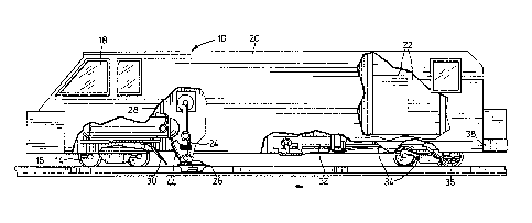
Figure 1 is a side elevational view of a vehic].e
incorporating this invention; and
Figure 2 is a railway track profile! showing typical
locations where surface hardening and/or rail rejuvenation
can take place in accordance with this invention.
DETAILED DESCRIPTION OF THE DRAWINGS
In the following description, it is assumed that the
apparatus for generating an energy beam includes a
11 ~ 3~835~
high-powered laser, specifically a CO2 laser which
generates an infra-red energy beam. However, it is
considered that the laser apparatus could be replaced by
other apparatus, for example that capable of generating
an out-of-vacuum electron beam.
In order to accomplish the laser transformation or
alloy hardening of railway tracks in accordance with
this invention, it is considered necessary to process
both rails simultaneously. This means that the vehicle
will require a duplicate set of equipment, one for each
rail.
Referring to Figure 1, a vehicle shown generally at
the numeral 10 is adapted to be pulled and powered by an
auxilliary small, shunting type, diesel-electric
locomotive. However, the vehicle 10 may also be
self-powered, as will be obvious to those skilled in the
art.
The vehicle 10 is provided with wheels 14 similar
to normal train wheels and adapted to ride along tracks
16, a cab 18 to house the operating personnel, two
lasers of which one can be seen at 20, electric power
supplies 22 for the two lasers, optical beam-transport
systems 24 (only one seen in Figure 1) for directing the
beam onto the track 16, optical application heads 26
capable of splitting the beam, if required, to produce
separated strips of hardened or alloy material on the
tracks 16, a tank 28 to hold a quenching liquid such as
oil or water, a liquid feed mechanism 30 located to the
left of the head 26 ~behind the head in the direction of
travel), a paint container 32, feed lines 34 to direct
paint to a paint applictor 36, and a latching apparatus
38 by which the vehicle 10 can be connected to a
locomotive to be pulled.
The power source in the pulling locomotive (or
built into the vehicle 10 if desired) would preferably
be a diesel-powered or gas~turbine electrical generator,
of sufficient capacity to operate the lasers 20 and
their associated peripheral equipment. The lasers 20
are typically high po~ered, continuous wave, carbon
12 ~ 2
dioxide lasers, each capable of continuously producing
an output beam power of 20 Kw or mor~. In addition,
each laser may be fitted with plasma or arc augmentation
equipment so as to provide additional keyhole energy fox
increasing the process speed.
For each laser, there is a beam transport and
application system, the control of which is located
inside the environmentally controlled cab 18. The beam
transport corridors are used to conduct the intense
beams from each laser to the respective rail su.rface.
Each transport subsystem incorporates a cylindrical
- beam-integrator line-focusing unit, to provide the
appropriate irradiance profile of the surface to be
laser hardened. The design and construction of these
beam systems provides for positional flexibility and
rail tracking, adequate for continuous profiled
illumination of the work piece.
Sequential control and process monitoring equipment
is part of the computer-based system, and provides
automatic operation of the laser hardening or alloying
process.
Each head 36 incorporates a paint spray syste~, to
apply to the respective rails the light-absorbing
coating required for efficient laser beam absorption.
~ Figure 2 shows the profile of a typical rail 16.
Located at the cap 40 of the rail 16 are two regions 42
and 43 that have been surface hardened. The region 42
is on the crown, whereas the region 43 is on the inside
edge of the cap 40. The hardened location 42 provides
for primary loading bearing, ~hile the side track
location 43 provides for wheel flange guidance.
In order to produce the two spaced-apart regions
42 and 43, the laser beam would have to be split
optically. This can be done with conventional optics
known in the field.
If desired, a variant of the invention may involve
utilizing an additional piece 44 of apparatus to provide
a fusible wire or metallic powder simultaneously with
the energy from the laser heam, 50 that the beam can
3 ~ ~
- 13 -
alloy into or fuse the metallic powder to the track. A
suitable material would be stellite, or some other hardening
alloying element.
In the case of the surface hardening process, it will
be understood that the speed of the vehicle 10 is such as to
move the beam longitudinally along the track at a speed which
allows the irradiated part of the track to be heated to a
temperature such that a given portion of the track becomes
hardened due to self-cooling from said temperakure after the
beam has passed further along the track. In the case of the
laser cladding or alloying of the track through the use of a
wire or metallic powder, the speed of the vehicle is such as
to progressively move the beam and the powder feeding
apparatus together longitudinally along the track at a speed
which allows the wire or powder to be alloyed into or fused
onto the track in at least one continuous strip to form a hard
and wear-resistant layer or channel.
In the case of the remelting of microcracks in a track,
it is preferable that the level of energy in the beam be high
enough to create a moving keyhole (a vapour space) in the
track at the location of incidence of the beam, whereby the
material surrounding the keyhole vapour spac~ is in molten
form and solidifies after the beam moves on. In the case of
alloying, the alloying wire or similar material can be fed
directly into such keyhole.
Numerous advantages can be gain~d from the use oE the
system described herein, which utilizes a laser as a heat
source and accomplishes an ln situ transformation of the
surface or near-surface layers of the track.
Some of the more obvious advantages are set forth below:
1. Good Surface Hardness with Inner Ductility
Since the laser energy is absorbed only near the
surface of the material being processed, only this particular
area (a relatively thin surface layer) is hardened.
Conse~uently the interior regions of the member retain their
full ductility and strength, with essentially no distortion.
~ 3:~3~2
In the case of bulk resolidification, for surface
alloying and/or microcrack elimination and repair,
actual melting of the rail material is required.
However, here also the interaction area is precisely
definable with respect of the width and depth achieved
within the remelted region. The previously mentioned
"keyhole" effect, that would probably be utilized in
this melting process, would considerahly enhance the
speed of the interaction, since laser energy could now
be more easily conducted into the rail material.
2. Energy Efficient and Cost Effective
Since the hardened skin depth ~case depth) can be
confined to a region extending into the bulk ~aterial
only about 2 to 5 mm from the surface, the process is
extremely energy efficient and cost effective. This is
in contrast to all other hardening techniques, including
the induction process~ The latter heats the material to
a much greater depth, thereby resulting in a less
efficient process which is usually accompanied by
distortion problems.
3. Optimization of Case Hardness, Depth and Geometry
Since laser energy and beam irradiance is subject
to precise specification and automatic control, it is
possible to produce a hardened zone of accurately
controlled depth and geometry. Thus the thickness and
width of the hardened layer, or layers, could be
designed and consistently produced to provide optimum
performance.
In general it is anticipated that a case depth of 1
to 2 mm would be adequate for most service conditions.
However, in track sections subject to excessive loading
and/or lateral stressing, such as joints and curves,
deeper case depths of up to 3 to S mm might be
desirable. Since the laser is amenable to fast
electronic control, such changes in case depth could be
achieved automatically, while still retaining good
energy efficiency.
1S 131~3~2
A thicker hardened region at the rail or wheel
surface might be desirable if "shelling" becomes a
problem with the smaller case depths.
For the variant in which the la5er hardening
5 optical system produces a plurality of parallel, narrow,
hardened stripes, rather than a hardening of the entire
rail surface, the individual hardened regions are
"locked in" by surrounding, more ductile material. In
consequence, the rail becomes far more resistant to
shelling effects, even in thin layers.
In the context of the maximum achievable process
rate and cost effectiveness, the optimum case depth
would be specified as the minimum thickness of the
hardened layer which could withstand indefinite service
without shelling or squating.
. Variability in Sha~ f Work Piece
Since the beam transport and focusing systems of a
laser hardening machine can be designed with a high
degree of flexibility, any variation in shape or
position of the area to be laser hardened can be easily
and quickly accommodated. Thus the full range of wear
surfaces found in the rail transport industry would be
amenable to this wear resistant laser hardening,
alloying cladding process, including wheels.
5. High Process Speed
The process speed can be very rapid if very large
lasers with plasma or arc augmentation are used. This
means that long lengths of railway may be hardened in
relatively short periods, thereby making the concept
operationally practical.
6. Non-Contacting Process with no Attached Equi~ment
Since the hardening process is a non-contacting one
(i.e. the laser energy is remotely beamed to the rail or
wheel surfaces to be hardened), and further since no
special equipment is required to be attached to the
rails etc., the entire process may be started and
stopped at will, and very quickly. Further this process
lends itself very well to use with a self-propelled
stand-alone vehicle of the kind described above in
16 ~ 2
connection with Figure 1. By providing the vehicle with
a 90 swivelling capability and rubber wheels set at
right angles to the rail wheels 14~ so that it can
quickly mount or dismount the railroad right-of-way at
any grade level crossing, the laser rail hardening
process can proceed almost continuously -- interrupted
only briefly as rail traffic perioditally comes along.
Alternatively, in track areas equipped with regularly
spaced off sidings, the vehicle could merely stop at
these points and allow the normal rail traffic to go by.
In this case the vehicle does no-t require extra wheels
to permit perpendicular movement at grade level
crossings.
7. Day Lon~_and Year Round Production
The laser hardening process could be done at any
time of the day or night and throughout the year,
largely irrespective of prevailing weather conditions.
Consequently the "equipment utilization factor" could be
high. This aspect would not only provide for good
yearly production rates but also for a speedy
amortization of the special laser-based hardening
machine required for the process.
8. Re-Application of Process
In heavily loaded and/or high traffic areas,
subject to excessive wear the hardening or alloying
process could be repeated at regular intervals, thereby
providing for an even greater extension of track
lifetime.
9. Hardening Process Applicable to Old Equipment
Since the process is a non-contacting interaction
only at the surface or near surface region, it would be
equally applicable to "old" track and to new,
irrespective of the physical condition of the steel
itself (i.e. dirty, rusted etc.).
10. Optional Use of Laser Cladding for Worn Track and
Equipment
As explained earlier, where excessive track wear
has already taken place it is possible to build-up and
thereby repair the rails by "laser claddin~" the
17 ~3~ 2
surface, using the addition of a wire or metallic
powder, and an attachment adapted -to feed the metallic
powder or wire to the rail. By the utilization of high
grade al1Oying wires or cladding powders such as
S stellite, a very hard wearing surface, much better than
the original steel itself, could be ~uickly and
economically achieved. Excessively worn wheels could
also be refurbished in situ, with laser cladding or
_
alloying techniqu~s.
ll. High Quality Mode Unnecessary
Since the process does not require a highly focused
- beam, it follows that a high quality laser beam with
well-defined or controlled mode shape is not necessary.
Simple "beam integrator optics" could provide adequate
uniformity of illumination, irrespective of the mode
pattern. Happily this feature considerably relaxes and
simplifies the optical aspects of the high power
required for the application.
12. Non-Precision Trackin~
Since the process is relatively non-precision with
respect to substrate illumination, an accurate beam
tracking system is not required. Thus simple follower
guide-wheels, placed on the rails themselves, would
provide all the accuracy that would be necessary.
13. Ease of Applying Absorbing Coating
Since experiment has shown that carbon dioxide
laser radiat-on is easily reflected by polished metallic
surfaces, it is necessary in most cases to coat the rail
surfaces with a thin layer of absorbing paint or the
like. As explained earlier, this process, already well
understood and utilized in the laser hardening field,
could be accomplished simply by spraying a thin coat of
black paint onto the rails, just immediately prior to
hardening. A small spray nozzle would be mounted
slightly above each track and somewhat ahead of the main
optical beam application systems.
In certain embodiments, it will be advantageous to
couple out and apply a small percentage of the laser
18 ~ 3 ~
radiation a few meters ahead of the main hardening beam,
so as to "pre-cure" this sprayed-on absorbing coating.
If, as in the case of rail alloying or rejuvenation
described earlier, the rail surface :is to be remelted,
or alternatively if a cladding material is to be added,
-then it would not b~ necessary to apply an absorbing
coating. This is the case because experiment has
documented that in each instance the molten material
itself provides adequate laser beam absorption.
14. Use of Lower Grade Steel
Since the laser transformation hardening process of
interest here has been shown to resuLt in a higher
hardness than that attainable with any other
conventional technique (iOe. RC 59-60~, even with most
low grade mild steels, it may be possible to use less
expensive grades of steel in the manufacture of rails,
if they are to be subsequently laser hardened.
Certainly it would not be necessary to specify the use
of costly chromium alloy steels~
15. Corrosion Resistance
Generally it has been shown that laser hardened
steels exhibit a much higher resistance to corxosion,
than do non-hardened materials. Consequently, rail and
other equipment so treated would be less prone to
corrosion cracking and deterioration, especially in
regions near salt water such as docks, ship yards, coast
lines, etc.
16. Labour Non-Intensive
Since the laser and its associated beam delivery
and tracking systems are computer controlled, an~ also
since the vehicle is essentially self-steering during
operation, the process requires very few people, perhaps
only 2 ~a laser technician and a laser operator).
ROCESS SPECIFICS
From an analysis of a variety of previous
experimental data on laser transformation hardening of
low carbon steels, it would appear that at an
illumination intensity of near 2~ Kw per square cm, a
process rate of about 5 square cm per second, with a
19 ~
case depth of 2 mm, can be achieved with 10.6 micron
radiation.
Consequently, using a ~W carbon dioxide laser o~ 40
Kw average beam power, one could transformati~n harden a
2 cm wide strip on -the cap, plus a 1 cm wide line on the
inside face of a standard transport rail at a linear
rate of about 3.5 cm/s. Two such lasers, one for each
rail, would thereby provide a railway hardening
production rate of over 400 feet per hour. Assuming
that the hardening process could be done all night and
for a period of about 6 hours during the day ~i.e. the
equivalent of about 20 hours of process time) then a
linear track hardening production rate of over 8,000
feet per day could be achieved.
If only a narrow channel or strip was to be melted
and resolidified then a ~0 Kw laser could be expected to
yield a production rate of about 9 cm/s. This would
translate into about 1000 feet of processed track per
hour. With anticipated improvements in lasers and
process efficiency, a production rate of near a half
mile per hour might ultimately be realizable. Also, if
plasma or arc augmentation culd be employed to convey
additional electrical energy into the keyhole via the
laser's ionization path, then a process rate about four
times faster could be achieved.
OPERATING COSTS
In one aspect of the laser hardening procedure
under consideration here, the material being processed
is not melted. Consequently no expensive He cover-gas
is required to protect the rail from the ambient air.
However, in the cases of alloying or cladding, the laser
does melt either the substrate or the alloying or
cladding material. Even in this case, an inexpensive
nitrogen or carbon dioxide cover-gas is expected to be
adequate.
These aspects, plus the fact that no ancillary
equipment is required to be attached to the rails, means
that the process costs could be quite low: essentially
3 ~
little more than the running cost of the lasers and the
salaries of the 2 operators.
While one embodi,ment of this invention has been
described hereinabove, it will evident to those skilled
in the art that changes and modifications may be made
therein, without departing from the essence of this
invention, as set forth in the appended claims. In
particular, it could be possible to utilize an
out-of-vacuum electron beam instead of a laser as the
primary beam energy sourceO