Note : Les descriptions sont présentées dans la langue officielle dans laquelle elles ont été soumises.
1 ~L319~3~
SCRE~N ~;~MULATOE~ WINDOW
~chnical Field
The present lnvention cel~tes to a screen ~im~l~tor
win~ow, th~ ob~ect o~ which i~ to provide ~o per~ons
viewin~ the window ~ re~ tic simulation o~ appa~en~
surr~unding6 and even~.
Simulator~ ~r~ currently used mainly ~o~ th0 tr~ining
o~ ~ervice personn~l p~rticul~rly ~i~craft pilot~, thc
~imulator ~ein~ Arran~ed so th~t the per~on concerned
looking into the ~imula~or window sees ~ eai~ly realLstic
repreaentation o~ ~ scene thak h~s been p~iou~ly
~eco~ed on fllm or video tape. simulators ~t pr~ent in
u~e are gen~rally suit~ble ~or viawing only by one or a
very small number o~ per~ons ~n~, ow~ng ~o the light
losses involve~ in such systems relatively low le~els of
illumination can be a ~ur~he~ limita~ion.
Th~ object of the p~6ent inventlon i~ to peovide
s~r~en ~i~ulato~ window w~ich can be viewcd by a
relatively large nu~b~r o~ p~rson~ to provide enh~nced
~O realism with less limitations ~n bright~ss. It i~ o
the o~ject o~ the invention to p~ovide ~ simulator window
which inc~ease~ the capAei~ies And en~nce~ the image~y of
~onv~ntio~al simula~or window~ ~hile r~duclng the eost of
c~nstructiOn.
Si~ul~tor window~ according to ~he inventlon may be
applied in ~ variety of wA~S. C~n~ example is an en~ sed
ea~in or oapsule havin~ ~ont ~nd ~ide windDws ~ith
pr~vision ~or 8eating a numbe~ o people who may be ealled
upon to imagine theJnselves in a ~s, ~rail, a~r~plane,
30 submarine or sp~ce capsule. In ~ac;h of ~he windows a
s~i~able scen~ is presented so thAt, ~o ~he person~ in the
cabin ~ t ~ppe~s that they ar~ making a journey on land,
~nde~ the ~ea or in space. In anothe~ applic~tion the
window may be ~sed a~ part of a ~ligh~ 6imulato~ or ra~ing
. 3S car ~imulator or the like~
~3~9~3PJ
2 74297-1
Sum~a~y of the Invention
The present invention provides a screen simulator window
comprising, means de-fining a window aperture through which a scene
may be viewed; a partial screen arranged immediately behind the
window, the screen consisting of alternate opaque screen portions
and transparent portions; means to cause adjacent opaque screen
portions and transparent portions to be transposed at a speed such
that the presence oE the screen is not apparent to the eye of a
viewer; rear surfaces of the opaque screen portions extending away
from the window being suitable for the reception of a projected
image; a projector arranged to project a scene upon said surfaces
of the opaque screen portions so that light from the projector is
not directly visible to a viewer of the window, the projected
scene appearing on the rear surface of the opaque screen portions;
and a mirror arranged behind the partial screen viewable through
the window, the scene projected onto the partial screen being
visible in the mirror through the window.
The partial screen used in the screen simulator window
according to the present invention may be constructed in a number
of different ways. In one embodiment of the invention the partial
screen comprises a plurality of spaced apart slats defining
between them a series of openings moved continuously past the
window or oscillating in front of it up and down or side to side.
In another embodiment a continuous screen is provided with an
array of spaced apart cut-outs, transparent portions or gaps or a
checkerboard array of screen and transparent portions. In a still
further embodiment the screen comprises a rotating disc comprising
a series of screen segments separated by gaps or transparent
~.
2a 1319~7 74297~1
segments.
In ye-t a further embodiment the partial screen comprises
an array of parallel slats each mounted to
` ~319~
- 3 -
rotate ~bou~ a lon~itudinal ~xis parallel ~o the
longitudinal axi~ o~ ~h~ ~la~ but lying outaid~ the ~lat.
In order to remov~ ~licker, sh~dow8 ~nd moir~ eE~ects lt
is ~esir~le tha~ the transparent ~nd ~cr~n por~ion~ of
S ~he ~cr~en are tr~nspo~ed At ~ r~e of ~t l~ast 45 per
~econd ~nd m~re pre~erably ~0 pe~ second.
~ is adv~n~geo~ th~t ~he screen ~nd the ~irror lie
in ~ubst~ntially p~r~ l planes in side by side ar~ay.
Th~s m~y b~ conveniently ~chieve~ i~ the ~creen is ~ormed
of ~ sheet o~ transparent materi~l ~u~ gl~ss ~o~ed
with a coating such ~ gal~n~u~ e~ e wh1ch may be
electricall~ ren~ered opa~ue or transparent~ This would
allow for ~one~ o~ the screen to be i~termlttently
~witched b~w~en b~ing tr~nsparent po~tions and bei~g
lS screen portiOn~ of the ~creen. The development o
coating which may be ~witched bet~een being reflective and
~eing transp~rent would allow the ~irror be fo~mRd in a
planar fc~rm s~mil21r to that of the ~creen.
The mirrOr may be a comple~e microc howeves in
preferred embodiments of the inven~ion ~he ~irror l~
either A moving p~rti~l mirror ha~ing re lective and
non-reflective portion~ or is a one w~y, or partial,
mirror. ~n particularl~ preferred embodiments of the
invention the mirro~ is ~ moving segmented mirror shape~
~S to h~v~ l~n~ proper~ when movin~. ~f the mirror i~
moving m;~ror having ~equenti~l re~lective ~nd
non~r~flective portions it i4 essential tha~ the
alte~n~tin~ non-reflective p~rtio~ o~ the mirror a~e in
regis~er with ~he screen portions of the ~oreen such that
light fcom the pro~ector i~ not ~rectly visible to
viewer of the window.
It i~ des~rable that ~ len~ be in~erposed 4etween the
~creen and a viewer in the ev~nt th~t the mirror i6 not
i~el~ curved such that it h~ it~ own lens p~operti~s.
~319Q3~
. ~ ~
Tha pre~ence of ~uch ~ lens c~n b~ ~&ed prim~r.i1y to pl~ce
the imag~ app~rentl~ at vl~l in~inlty.
I~ is e~entiA1 to th~ present invention ~hat the
lmage pro~ected ~rom the proj~ctor i~ orme~ fir8tly on
partial ~cree~ whi~h i~age is th~n ~eflectod by ~ mi~ror
to the viewer. The mere re~l~ction o~ ~n image onto a
partial screen will not provide the advan~ageS o~ th~
arrangement according to this inventio~. The~ advan~es
~re, ln prefe~r~d ~mbodiment8 o the inventiOn, RS
1~ ~ollow~;~
i) imag~s may ~e viQwed ~omfortably, pr~cise~y and
in appropriate p~rspe~tive from rela~ively clo~e
proximity and ~lmo~t any ~ngle;
ii~ the position o~ the image can ~ppe~r to he
clearly contiguou~ with the gides o~ th~ window
apeF~ure not at ~ distance out~id~ the window;
iii) it is not pos~ible to see pa~, aro~nd, behind
o~ be~we~n ~he image and the surcounding side~ o the
window ~per~ure an~
iv) the i~age ~ize is the ~ize o~ the viewing
wlndow no~ a larg~r siPe fu~ther away; consequently
equipment costs and dimensi~ns are redu~ed
subst~ntially.
Th~ proiector m~y be ~ny convqntiona1 projec~or u~ing
ordinary o~ laser light. The imag~ may be prere~orded o~
film or tape or may ~e a "liv~" projec~ion o~ an event
taki~g pla~ at a dist~nce.
ie~ Deser iption o the D~awing
~hs inven~ion m~y be embodied in a variety o
dl~feren~ form~ and in order that the n~ture o~ the
inve~tion may be be~ter understood a plurality of ~ch
forms ~e d~scribed ~y way o~ ex~mple in ~he ~ccompanyLng
~iag~mm~tic drawiny~ in whiah:-
F1g. 1 is ~n elevation showin9 A person seat~ by the
3S sLde o~ a screen simul~tor window accordiny to tha
. ~ :
:153~9~37
inven~ ion;
~ ig, 2 i~ ~ soCtiOnAl view Of the s~e~n simul~to~
window o~ Fig. 1;
Fi~. 3 i~ the ~ctionAl Vi~w o~ ~ modi~ied P~ o~
the invention illust~ating ~he u~e o~ a ~ota~ing mirror;
~ i~. 4 i~ a simllar view o A ~ u~the~ ~orm of
the inven~ion;
Fig. 5 16 a ~ection~l vi~w ~howing the u~e of a
~otating mirror and a rotating sa~e~n
Fig. ~ is a view in elevation of the ar~angement
shown in Fig~ 5.
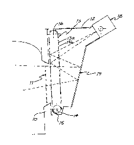
F~g. 7 ib ~ diag~ammatic perspec~iv~ view of a
further embodiment o~ the p~e~nt invention;
Fig. ~ is a si~ilar view o~ a further ombodi~ent ~f
the invention;
Fiy. 9 i~ a similar vi~w of a still further
embodiment of the inventiOn;
Fig, 10 i a simil~r view of yet ~nothe~ ~mbodiment
o the ~nvention; and
Fig~ ll is a vertical section~l view ~h~ough a
.~urther ~mbodi~ent of ~he inventio~.
Best ~ode fo~ Car~ying Out the Invention
It i~ to be emph~ized ~hat the drawing~ ~esc~ibed
above are purely diagram~atic ~nd a~e ~o~ ~he p~rpo~e of
explainin~ the principles o~ the i~v~ntion. In tho
~ollowing description 5imiI~r p~rts in differen~
embodi~e~ts of the invention ~r~ given ~he s~m~ nu~bers.
In Fig. 1 ~ seated ~igure is s~en at one si~e of th~
window opening l0 which may b~ conside~ed ~5 con~tit~ing
~ side window o~ a cabin i~ which a numb~r o pe~sons a~e
~eated. In practice the ~abin would have window openings
at the ~ront and At each ~ide.
mmediately 4ehind the ~indow openl~g 10 is ~
window 11 of polarising glaæs and ~rranged behind this a
light ~ox 12 within which iS a ~latted screen 13
$3
.: . .
~3~ ~37
s -
con~sting o~ ~ltern~te horiz~ntal ~l~ts 13~ ~Gp~r~ted by
~aps 13b, the gaps being in thi~ c~E;e o ~3u~1 width. ~he
scr~an 13 i5 cacried on band~ 14 o~ xi~le mat~ri~l
which pass over uppe~ and lower pulleys, lS an~ 16
5 re~pec~ively~ the low~r pulley lS b~ing rot~ted by a
motoc 17 ~o that the ~cr~n 13 pas~es ~;c~oss ~he willdow
opening lO at ~ spqed such ~hat it~ slatted nature is not
app~:en~ ~o the ~ye c: ~ a per~on in the c~bin. A varia41e
axis film or o~her proj~ctor 1~ i~; ac~.n~d to p~oj~ct ~n
10 imag~ lnto the &creen 13 in the m;~nner illu~tra~ed in
Fig. 2, the p~o~ect~r lB ~eing o~lt of ~ight of persons
seated in the ~abin. It will be ~ieen that r~y~ of light
f rom the pro~ector must pass throu~h ~he re~rmo~t run o~
the screen 13 be~ore striking the rear o~ the ~lat~ o the
15 run ~djacent ~he window 11. This re~ult~i in ~ ~ul~tan~ial
lo~s o~ ligh~ from the projecto~ and in o~de~ 'ch~t the
viewed scene shall appear to bq ~d~quately illumina~ed a
very powerful pro jec;tOr , or ~xe~ple c)~ the order of 5
kilowatts is requ~.red. ~he s::ene proj~cted onto the r~ar
~0 of the slats o~ the ~ron~ run o~ the sc:reerl i~ visible
through the window 11 $n the mircor 19.
~ he ar range~nent shown in ~ig . 2 ha~; the inherent
disadvantage that a person in the çabin looking upw~rdly
or downwardly will ~ee par~s of the z~pp~ratus ~bove or
2~ b~low the mir~or th~s destroying the realism of the
pre~entatiOn~ with ~ ~/iew ~o avoiding this the mirror 19
is cons~ructed as shown in Fig. 3, tha~ iS to sa~ in ~he
form 0~ a nun~ber of radially ex~ending elements arranged
on the sUr~ace of a Cone. In ~his case the mlrror is
30 rota'ced by mean~ of the moto~ 21. Wi~.h thiS arrangem&nt
even if a vieweL look; upw~dly or downwardly ~he
pro~ected scene ~ill still be seen in the mirror which is
rotated at ~ speed such a~ to ~iv~ the appearar!~e of a
complete mi r ror .
~S With the arrangement shown in Fig. 2 ther~ is a very
.: ,
3 ~
~ 7 -
cDnside~ab~e loss of li~ht d~ to the neo~ssity ~or thfl
light f~om the proiecto~ to pa s ~hrough ~he run o~ the
slatted screen 13 remote ~rom th~ mirror. Fig. ~ showg ~n
ar~angement co~ce~ponding to ~hat of Fig~. 2 and 3 in
which ligh~ loss is reduced by the provision of mean~
~no~ u~trated) which have th~ ef~ o~ sot~tlng the
~l~ts o~ the 8creen thro~gh 90 so th~t thero is less
lnter~er~nce with the light from the pro~eeto~ by th~
return run of the slatted s~e~n. ~he ~o~ o~ this
howe~r is ~eater ~omplication ~nd ~o~e noi~e ~n
operation.
Fi~3 . 5 and 6 ~how a more refine~ embodiment o~ the
invention in w~1ch both th~ ~a~t~d 6cree~ ~nd the mirror
are purely rotary element~. ~he principle o~ operation i~
the same as tha~ des~ribed ~bove. In thi~ c~se however
the screen slats are carried in ~ wheel which i~ rotated
by ~he motor 17 which also rota~es the mirror~ As in the
previous embodi~ent ~he f~ce~ o~ the 81at~ pointing away
from the windaw are c~ated with a material ~uitable ~or
pro~e~tion screen ~nd the ecene ~rojected fro~ th~
projector 1~ is seen re~leo~2d in the eleme~ts of the
mirror l9. In this ca~e the be~m rom the projector la
must pass through the mirror e1e~en~s l9 and these are
th~refore in the form of hal silvered mirro~ which
~5 permit l~oth ~r~nsmi~sJ on e~nd ref le~ti4n of light.
Fig~ 7 shqwsi ~n arranq~?men~ in which the ~cre~n 13
an~ the mirror 19 Are e~ch m~de up of ~n a~ray o~ angled
~lats. A pair of moto~ nd 22 c~use the slats o~ the
screen 13 and of the mi~ror 19, ~pectiv~ly, to oscll~atc
in ~ ve~ti~al direction i~ synchrony. A lenæ 23 is
posi~ioned in fron~ of ~h~ screen 13 to imp~ove the
sharpness of the im~ge and it~ depth o ield.
Fi~, B shows an ~r~n~ement i~ which the scr~cn 13
~nd the mirror 1~ are e~h compri~ed o ~onti~uo~ bandæ
3S carryin~ a chequerbo~rd matrix of ~ransp~r~nt ~nd opa~u~
oo
lL3~ 9037
portions. The opaque por~ions 13a o~ the ~cr~n 13 a~o
coated with a scr~en mat~rial whll~ thoso o ~he mirror lg
are refl~c~ive. Motors 21 and ~ rot~e roller~ carryin~
the s~een 13 ~nd the mirror 19 ln syn~hr~ny~
In the arrang~ment shown in ~ig, ~ ~he ~cre~n 13 and
the mic~or 19 are each focmed of a glass she~t co~ted with
a ~ of a galenium arsenid~ m~erial capable o~ b~ing
selectively rend~red opaque or transp~r~n~ by an ~ t~ic
cu~ren~ or volt~ge ~h~nge, In the ~ase o ~h~ ~creen 13
lo the film i~ rende~ed 4paque to Xorm s~reen porti~n~ 13
and rendered transpa~ent to o~m the ~ran6parent
po~tion~ 13h. In the micror 1~ ~h~ ~ilm is such th~t it
i~ roflective when it i~ rende~ed opaque. I~ e~ch case by
alternating the current and or voltage appropri~tely th~
lS adiacent opaq~e and transparent portions may be tran~poaed.
O~vio~sly ~he transposition o~ the o~aqu~ and t~ansp~rent
portlons of the scr~en 13 will alt~rnate with the
transposition o th~e portions o ~he mir~or 1~ so that
at no tlm~ can light from ~he p~iector l& ~all directly
onto ~ viewer viewing the i~g~ th~ou~h len~ 23.
In Fig. 10 an arr~ngement i~ $hown in which the
s~re~n 13 and mirror 19 are ~ach ~ormed by a ~ontinuou~
t~be conta~ning alternatin~ transp~rent and opa~e ~Ibe~d~
o a solid or liquid m~ter ial . ~h~ ~'beads" ~re pumped
2S through the respec~ive tubes in syn~hronis~ to prod~ce the
appeopr~ate tran~position of the transparent "beads" and
the opaque or reflective "bead~" ~5 the cas~ ~y be.
Fig. 11 show~ an arr~ngement in whi~h the sc~en 13
and thc mirror 19 are each forme~ f ro~ an array o slats
which are e~ch mo~nt~d at each end to extend t~ngentially
from a c~lind~ic~1 bu&h 24 and 25 re~pectively. ~he
bushes 24, 25 ~r~ rota~ed 3bout their longitudinal axes to
cause the slats o the screen 13 and th~ mir~or 19 to
rot~te about ~he said longitudina~ ~xis. Thi~ ro~otion
35 c~uses the alternat~ creation of scre~n poetions 13a and
~3~903~
,. 9 .
tc~n~par~nt portlon~ 13b and similary cau~e~ thc mirror ~o
~ct ~ a partial ~ir~or. ~h~ pro~e~to~ 1~ c~usee the
~o~m~tion of an imago on the ~e o~ ~h~ ~cc~en
po~tio~s 13a ~ist~l ~o the window, This image i~
reflected by ~he mirroC ~ to thR Rye o~ ~ viewes. The
~læt~ are rotated ~t su~icient ~p09d that th~ ~creen 13
is no~ visible ~o th~ vi~w~r who only ~ee~ the re~lected
im~ge ~s a continuous ~cene.
Experiments have shown that ~he inv~ntion i~ ~apAbl~
of providing a s~ene in a ~indow in whi~h ~here i~ no
ernlble ~r~en upon whi~h imayery i5 peojected and the
irna~e Appears in spac~ gr~in fre~ and distortioh free ~rom
any ang 1 e .
The embo~im~nts of ~he invent~on de~c~ib¢d abo~e are
lS ~iven by ~ay o~ exa~ple only ~o ~ssiB~ in o~r
understanding o~ th~ nature of th~ inven~ion.
~0