Note : Les descriptions sont présentées dans la langue officielle dans laquelle elles ont été soumises.
~319~
1 BACKGROUND OF THE INVENTION
FIELD OF THE INVENTION
The present lnvention relates to a device for
measuring pupillary distance (referred to also as PD value
hereinafter) of a subject to obtain data necessary for
optimumly setting a lens in a spectacle frame.
Setting of a lens in spectacles frame essentially
requires that the visual axis of the subject at a viewing
distance under an average state of use coincides with
the optical axis of the lens. In particular, a high degree
of coincidence is required in the case of a progressive
lens which has recently been developed and put into use.
In general, a progressive lens comprises three portions
of different optical characteristics: namely, a far-
vision portion which is used when sighting an object whichis at a long distance from the subject, a near-vision
portion which is used when sighting an object which is
at a short distance from the subject, and a progressive
portion in which a progressive zone is an optically
usable region. When sighting condition with this lens is
changed from a far-vision state to a near-vision state,
it is necessary that the visual axis is progressively
moved from the far-vision portion to the near-vision
portion, across the narrow progressive zone.
Any discrepancy between the visual axis of the
- 1 - ~
131~2~
1 subject and the optical axis of the lens causes problems
such as generation of prism or failure in obtaining
expected correction effect.
~ typical known pupillary distance measuring
device has the following construction. When the subject
is made to sight at a spot ligh-t source (a fixation
target), a cornea reflection image (bright spot) is formed.
The position of this bright spot as viewed from the same
side as the light source is defined as a vertex of cornea.
The position of the vertex of cornea is regarded as the
position passed by the visual axis. The distance between
the vertex of cornea and the nose of the subject is
measured as the pupillary distance. The viewing distance
is variable by shifting a convexed lens.
This known arrangement is disclosed in detail
in the specification of the United States Patent No.
3,495,897. The shifting of the convexed lens requires a
linear motion mechanism including various parts such as
a viewing distance setting knob, a slide guide interlocked
with the knob, a connecting rod and so forth, with the
result that the device as a whole is highly complicated
in construction.
SU~ARY OF THE INVENTION
The known pupillary distance measuring device
suffers from various other drawbacks or inconveniences.
For instance, it is necessary to set the
viewing distance for each of individual subjects. In case
-- 2
13~2~
1 of a multi-focus lens which requires measurement at a
plurality of viewing distances, the measurement has to be
repeated from the beginning. In some cases, the subject
who has looked into the pupillary distance measuring
device falls in a temporary "machine near sightedness"
state so that the fixation target at an infinite distance
cannot be imaged as a fusion, with the result that the
measurement cannot be conducted.
Accordingly, an object of the present invention
is to overcome the above-described problems of the prior
art.
To this end, according to the present invention,
there is provided a device for measuring pupillary
distance comprising: sight spot forming means disposed
in the device and including a light source; a window
provided in a front panel of the device in such a manner
as to enable a subject to look at the sight spot in the
device; locating means for locating the front panel
properly in relation to the face of the subject; a
converging lens fixed in the device such that the
appearant viewing distance of the fixation target has a
predetermined distance value and disposed corresponding
to at least an eye of the subject; sighting mark forming
means provided on the inner side of the front panel such
as to form a sighting mark which corresponds to the
position of a cornea reflection image of the fixation
target formed on the cornea of the subject; sighting mark
position control means for enabling an inspector to control
-- 3 --
~3192~
1 the position of the sighting mark in relation to the
position of the cornea reflection image; observation
means for enabling the inspector to observe the front
portion of an eye of the subject; sighting mark position
reading means capable of reading the position of the
sighting mark; viewing distance setting means for setting
the viewing distance at which the pupillary distance i5
to be determined; computing means for computing the
pupillary distance at the viewing distance set by the
viewing distance setting means; and display means for
displaying the result of computation; whereby the pupillary
distance at a desired viewing distance can be determined
from the result of measurement of the pupillary distance
at a preselected viewing distance.
In operation, after the front panel of the
device are properly positioned to the subject, the
subject is made to sight, through the window portion,
at a fixation target which is appearantly located, by
virtue of the converging lens, at a predetermined viewing
distance. In this state, the inspector operates the device
to move the sighting mark such that a predetermined
positional relationship is established between the cornea
reflection image and the sighting mark. The device then
automatically reads the position of the sighting mark.
Then, the inspector sets a viewing distance for the
pupillary distance in question, the device computes the
pupillary distance at the set viewing distance on the
basis of the position of the sighting mark and displays
-- 4 --
13192~
1 the required pupillary distance on the display section
of the device.
With the pupillary distance measuring device
of the present invention, therefore, the inspector can
know the pupillary distances for individual subjects, from
a single predetermined viewing distance. In addition,
pupillary distance data concerning pupillary distances
at a plurality of viewing distances as required in the
case of a progressive lens can easily be obtained simply
by switching the viewing distance. Even if "machine near
sightedness" has taken place, a fusion of the fixation
target can be formed by operating the device so as to
reduce the viewing distance, so that the required pupillary
distance can be obtained. As the position of the sighting
mark can be placed on a position having a voluntary
distance from the vertex of cornea of the subject, it is
not only easy to produce the device but also unnecessary
to adjust the device for exporting, alternatively simply
changing a set of the value in the computer being enough
to measure.
The principle of the measurement with the device
for measuring pupillary distance according to the present
invention will be described hereunder.
The pupillary distance (PD value) used in
spectacles dispensation in the value which is to be
obtained at a position ordinarily occupied by the
spectacles lens when the user or subject wears the
spectacles. The distance between this lens position and
-- 5 --
13~ 928~
1 the vertex of cornea is referred to as "vertex distance"
and usually about 12 mm in case of Japanese and about
13.75 mm in case of western people as standard.
~nd the distance from the vertex of cornea to
the rotation center is estimated to be about 13 mm in
many papers. So that value is used in the present
invention, but it is correctable on the basis of
experience.
Fig. 1 illustrates the state of the subject's
eye directing its visual axis towards the fixation target
spaced at distance "a" (mm) in front of the eye. When the
viewing target is on the visual axis, the cornea
reflection image is on it, too. So the relationship
between PD~ which is PD value at infinity and PDm which
is PD value at distance "b" is represented by the following
formula.
PDm a-b
=
PD~ a+c
where "c" represents the distance from the vertex of
cornea to the rotation center. Assumming that the value
"a" is 1000 mm, the distance "b" is 30 mm and the
distance "c" is 13 mm.
PDm = 0.9576
PD~
PD~ = 1.0443 PDm.
Then Fig. 2 illustrates the state of the eye sighting a
fixation target spaced at the viewing distance L. The
-- 6 --
13~2~
1 relationship between PD~ and the PD value (PD) at the
vertex distance (VD) is as follows;
PD = PD~ x D
L~c
assuming that the "VD" is 12 mm and the "c" is 13 mm,
PD -, 1.0443 PDm x -
L~13
Thus once PDm is measured, it's possible to obtain PD
values at any viewing distance.
BRIEF DESCRIPTION OF THE DRAWINGS
Figs. 1 and 2 are illustrations explanatory of
the principle of the pupillary distance measuring device
in accordance with the present invention;
Fig. 3 is a sectional view of an embodiment of
the present invention;
Fig. 4A shows an appearance of an embodiment as
viewed from the subject side;
Fig. 4B is a plan view of the embodiment shown
in Fig. 4A;
Fig. 5 is an illustration of the shape and
construction of a liquid crystal display incorporated in
the embodiment of Fig. 3;
E`ig. 6 is a block diagram of an electrical system
in the embodiment shown in Fig. 3;
Fig. 7 is a sectional view of a modification
of the embodiment shown in Fig. 3;
-- 7 --
131~2g~
1 Fig. 8 is a sectional side elevation of the
embodiment according to -the invention shown in Fig. 3; and
Fig. ~ is a sectional side elevation of
modification of the embodiment shown in Fig. 3.
DESCRIPTION OF THE PREFERRED EMBODIMENTS
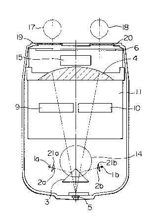
Referring to the drawings, fixation target
illuminating light sources la and lb for right and left
eyes are arranged to illuminate dot-like fixation targets
2a, 2b which are adhered to the front side of condenser
lenses 21a and 21b.
The pupillary distance measuring device of the
present invention does not incorporate each light shield
plate which is usually used for shielding one of two eyes.
Measurement of each eye is made possible by selectively
turning on and off one of the illuminating light sources
la and lb for right and left eyes.
In case of mounting a fixation target for common
use to both eyes, it is necessary to enable to insert
into the light axis the light shield plate for shielding
one of eyes.
A reference numeral 3 denotes a total reflection
mirror. The arrangement is such that the optical axis
of the fixation target and the optical axis of observation
of the inspector are slightly discrepant from each other in
the vertical direction. Obviously, it is possible to arrange
such that both optical axes coincide with each other,
provided that a half mirror is used in place of the total
reflection mirror, though the light quantity is reduced
13~92~
l almost to a half value. (see Figs. 8 and 9)
The focal distance and the position of an
objective lens 4 are so determined that the fusion of the
fixation target can easily be formed. Namely, the
illustrated embodiment is designed such that the viewing
distance is l m. Since the objective lens is immovable,
it is easy to arrange each objective lens for the right
and left eyes. Whether a pair of objeetive lenses for
both eyes or a single objective lens is used is a matter
of design and production technic. (see Fig. 7)
An eyepiece 5 enables the inspector to observe
a cornea refleetion image (bright spot) formed on the
cornea of the subject.
A liquid erystal display unit (LCD) 6 of light-
transmitting type is disposed at a distance of 30 mm fromthe vertex of the eornea of the subject. The distanee
value of 30 mm is not critieal but it is significant that
the distance is known.
Fig. 5 shows the shape and eonstruetion of a
liquid erystal display 6. As will be seen from this
Figure, the liquid-erystal display unit 6 used in this
embodiment is a segment type unit beeause the objeet of
the device is limited to the eolleetion of data necessary
for setting a speetaeles lens in a spectacles frame in
respeet of faeility to operate the unit. Each segment 40
is formed by conducting photo-etching on glass eoated
with a transparent metal coating layer and, henee,
exhibits a high degree of preeision. Numerals 41 and 42
g
13~2~
1 denote a polarizing plate and a liquid crystal which are
essential portions of the liquid-crystal display unit 6.
When a voltage is applied to one of the segments 40, the
segment 40 becomes opaque so that a black line (referred
to as "hair-line pattern) is displayed.
Obviously, the liquid crystal display unit 6
may be of a matrix type as shown in the specification of
the United States Patent No. 4,591,246. In such a case,
it is not necessary to use the hair-line pattern.
The hai.r-line pattern is progressively movable
to the left and right by an amount proportional to a value
input to a microcomputer 15, the input being obtained
through an A/D conversion of output voltages derived from
linear potentiometers 9 and 10.
The pupillary distance measuring knobs 7 and 8
are operatively connected to linear potentiometers 9 and
10 respectively so that these linear potentiometers are
capable of outputting voltages proportional to the amount
of operation of the pupillary distance measuring knobs
7 and 8.
The microcomputer 15 and a liquid-crystal
display unit 12 for displaying the results of computation
are mounted in a circuit board 11, together with other
components.
A viewing distance setting knob 13 is directly
connected to the potentiometer 14. Read switch 16 is the
switch for inputting to the microcomputer the voltage
signal of linea potentiometer, which signal is A/D
converted. When the hair-line pattern has coincided with
-- 10 --
131~2~
1 the cornea reflection image of the fixation target, the
inspector pushes the switch 16 so that the A/D converted
voltage signal, corresponding to that position of the hair-
line pattern, is input to the microcomputer.
Numerals 17 and 18 denote right and left eyes of
a sub~ect, which are protected by protective glasses 19
and 20.
As shown in Fig. 6, the electric circuit
incorporated in the pupillary distance measuring device of
this embodiment includes an A/D converter 30 for conducting
A/D conversion of outputs from the linear potentiometers
9 and 10, liquid-crystal display (LCD~ drivers 31 and 32,
a battery 33 and a battery voltage detector (VOLTAGE
DETECTOR) 34. The electric circuit further includes a
power supply switch 35, and a select switch 36 for enabling
selection of the inspection mode between a both-eyes
inspection mode in which both the right and left eyes are
inspected and a single-eye inspection mode in which either
the right or left eye is inspected. The illumination
light sources la and lb are turned on and off in accordance
with the state of this select switeh 36.
Though the sighting mark to positioned in
relation to the bright spot is constituted by a liquid-
crystal unit, this is only illustrative and the arrangement
may be such that the sighting mark is formed of a hairly
thin bar which is mechanically movable accompanied by a
brush slidable on an encoder so that the required
information is derived from the encoder.
-- 11 --