Note : Les descriptions sont présentées dans la langue officielle dans laquelle elles ont été soumises.
~320137
BACKGROUND OF THE INVENTION
1. Field of The Invention.
This invention relates to new and improved
apparatus and method for the vir~ually immediate and
substantially complete separation of immiscible liquids;
which are particularly adapted to such separation of sample
liquids from immiscible isolation liquids within which the
sample liquids are encapsulated for minimization of sample
liquid carryover attendant automated sample liquid analysis.
2. Description of the prior art.
Although a number of apparatus and methods are
known for the substantial separation of sample liquids from
immiscible isolation liquids within which the same are encap-
sulated for minimization of sample liquid carryover attendant
sample liquid analysis, these will generally be found to rely
primarily upon the natural separational effects of the diff-
erences in specific gravity between those liquids, and are thus
not effective to accomplish the virtually immediate, and complete
in terms of totally different locations of the thusly substantially
separated liquids, separation of the liquids as are inherently
provided by the apparatus and method of this invention.
More specifically, United States Patent 4,121,466
issued October 24, 1978 to Allen Reickler, et al, for "Liquid
Dispenser With An Improved Probe" and assigned to the assignee hereo
discloses the use of an immiscible hydrophobic isolation liquid
2622-A
~32~7
to encapsulate successive aqueous sample liquids for
minimization of sample liquid carryover attendant sample
liquid analysis. In this apparatus, wherein the isolation
liquid is of greater density than the sample liquids,
the former is simply allowed to settle out from the latter
to the bottom of a reaction receptacle into which the
isolation liquid-encapsulated sample liquids are dispensed,
thereby leaving the sample liquid readily accessible for
reaction with reagent liquids as may then be .introduced into
the receptacle. This settling out of the isolation liquid
can and does take time and, in any event, leaves the thusly
separated isolation and sample liquids in essentially the
same location, e.g. the reaction receptacle.
In like manner, United States Patent 4,357,301
is~ued November 2, 1982 to Michael M. Cassaday, et al for
"Reaction Cuvette" and assigned to the assignee hereof, also
, .
discloses the sue of an immiscible isolation liquid to --
"
encapsulate successive aqueous sample liquids for minimization
of sample liquid carryover attendant sample liquid analysis.
In this apparatus wherein the isolation liquid is again
hydrophobic and apparently ofgreater density than the sample
liquids, sharp projections or the like of a hydrophilic
:
material are provided at the bottom of the reaction cuvette,
and operate to puncture the isolation liquid-encapsulated
;~ sample liquids as the same are introduced into the cuvette;
-2
622-A
~3~0~37
thereby freeing for reaction the sample liquids from the
isolation liquid which essentially sinks to the bottom of
the cuvette. Again, this separation can and does take time
and, in any event, leaves the isolation liquid and sample
liquids in the location, e.g. the reaction cuvette and, of
course, in substantial surface contact at the isolation liquid-
sample liquid interface.
Under the above circumstances, it has been determined
by applicants that the continued presence of the "separated"
isolation liquid with the sample liquid at essentially the same
location, and with substantial surface contact therebetween
at the isolation liquid-sample liquid interface, can and does
present significant problems with regard to the accuracy of
subsequent sample liquid analysis results; and especially in
those instances wherein those sample liquid analysis results
are arrived at through use of sample liquid analysis method-
ologies involving, for example, reflectance spectroscopy or ion
selective electrodes, colorimetry, cell counting and/or enzyme
coil operation.
Hydrophobic filtration, for example as disclosed by the
"non-wet" filter of United States Patent issued May 12, 1981 to
David 5. Akhavi for "Blood 5ampleri" wherein a filter of hydro-
phobic material is used to prevent the escape of an aqueous sample
liquid from a collection device while permitting the passage of
air therethrough to enable filling of the device, is also known
in ~he prior art; but is not seen as relevant to the separation
of immiscible liquids as disclosed herein.
--3--
2622-A
:1320~37
Also of limited relevance to immiscible liquid
separation are conventional debubbler devices which have now
become standard in continuous flow sample liquid analysis systems
and which operate to remove the air segments from a continuously
flowing, air segmented sample liquid stream prior to sample
liquid analysis. These debubbler devices, which operate
primarily on the very significant differences in specific
gravity between air and sample liquids are clearly totally
irrelevant to the separa~ion of immiscible liquids as disclosed
herein.
No relevant prior art is, in any event, known to
applicants with regard to the combination o~ immiscible sample
and isolation liquid separational and sample liquid reaction
devices to effectively combine those functions in `the manner
made possible by the apparatus and rethod of this invention.
:
:
::
:: :
-4-
2622-A
-
~ 3~137
OBJECTS OF THE_INVENTION
It is ! accordingly, and object of our invention
to provide new and improved apparatus and method for the
separation of immiscible liquids.
It is another object of our invention to provide
apparatus and method as above which are opexable to effect
the virtually immediate separation of such liquids.
It is another object of our invention to provide
apparatus and method as above which are operable to separate
said liquids to distinct and spaced locations without
contact therebetween.
It is another object of our invention to provide
apparatus and method as above which are of particularly
simple and straightforward configuration and manner of
operation.
It is another object of our invention to provide
apparatus as above which have no moving parts.
It is another object~of our invention to provide
apparatus as above which~require the use of only readily
available, relatively inexpensive materials of proven
: :
effectiveness for the task and hand, and minimal if any
~modification of those materlals, in the fabrication thereof.
-5-
2622-A
13201~
It is another object of our invention to
provide apparatus as above which may be fabricated at low
cost.
It is another object of our invention to provide-
apparatus as above which are disposable in economically
- feasibl~ manner after but a single use.
It is another object of our invention to provide
apparatus and method as above which are particularly adapted
to the separation of immiscible li~uids wherein one of
said liquids is substantially encapsulated in the other of
said liquids.
It is another object of our invention to provide
apparatus and method as above which are particularly adapted
to the separation o immiscible liguids wherein one of said
liquids is an aqueous liquid.
It is another ohject of our invention to provide
apparatus and method as above which are particularly adapted
to the separation of immiscible liquids wherein one of said
~liquids is a sample liquid which ls to ~e subsequently
analy~ed.
; It is a another object~of our invention to provide
~apparatus and method~as; above whlch are particularly adapted
to the separation oE immlscib1e 11quids wherein one of said
` ~ liquids is a sample liquid which is to be subsequently
:: : : : :
-6-
2622-~ ~
~3~137
analyzed, and the other of said liquids is an isolation
liquid which has been utilized with said sample liquid to
minimize sample liquid carryover attendant the supply and
processing for analysis of successive sample liquids.
It is a further object of our invention to provide
apparatus and method as above for utilization in combination
with a sample liquid reaction device to effectively combine
the sample liquid separation and reaction operations.
2622-A
~32~37
SUMMARY OF THE INVENTION
As disclosed herein, the new and improved apparatus
and method of our invention are embodied in immiscible liquid
separation means comprising a liquid separator piece of a
material including a surface which i5 effective to preferentially
attract and sorb a first of the immiscible liquids to the
substantial exclusion of a second of said liquids. The separa-
tor piece is arranged relative to a common source of said
immlscible liquids to dispose the surface below that liquids
source and in essential vertical alignment therewith, thereby
enabling the liquids to be dropped onto the surface from the
common liquids source. As the immiscible liquids come into
contact with the separator piece surface, the first liquid is
preferentially attracted to and sorbed by the surface to the
substantial exclusion of the second liquid to thereby substant-
ially separate the liquids. The separator piece surface may
be amintained essentailly level for retention of the substant-
ially separated second lîquid thereon, or may be inclined for
the flow of the same therefrom under the infuence of the force
of yravity. As another alternative, the material of the
separator piece may be permeable by the substantially separated
second liquld for~the flow of the same therethrough and there-
from under the in1uence of~the force of gravity.
The separator~piece~takes~the form of a strip of
the~material, or a flexlble roll of the same;; and, in the latter
instance, means are provided to unwind the roll to progressively
~, `: :
expose~different surface portions of the material roll to the
--8~
2622-A
132~37
first and second immiscible liquids. For use with second
liquids which are constituted by aqueous liquids, the first
liquid is hydrophobic, and the separator piece surface is
either hydrophobic and provided by the material of the
spearator piece, or super-hydrophobic and provided by a
coating on the separatox piece.
The apparatus and method of the invention are
particularly adapted for use attendant the analysis of
successive aqueous sample liquids. For such use, the first
liquid is a hydrophobic isolation liquid which substantially
encapsulates the successive sample liquids to minimize
carryover therebetween, while the thusly encapsulated sample
liquids are the second liquid. 5ubstantial separation of the
isolation and sample liquids is dictated in such instance by
the fact that the isolation liquid-encapsulated sample liquids
cannot, as such, be analyzed with the requisite high degree of
sample liquid analysis accuracy.
Combination of the apparatus and method of the
invention with a sample liquid reaction devlce operates to
effectively combine the sample liquid separation and reaction
operations in a single device throuyh use of a permeable
~liquid~separator piece and disposition of a sample liquid
reaction element~directly thereunder.
_g_
2622-A
13~0~37
DESCRIPTION OF THE DRAWINGS
The above and other objects and signiflcant
advantages of our invention are believed made clear by
the following detailed description thereof taken in
conjunction with the accompanying drawings wherain:
FIG. 1 is a perspective view, with part broken
away, of a first embodiment of apparatus representatively
confiured and operable in accordance with the teachings
of our invention;
FIG. 2 is a perspective view of a second embodi-
ment of apparatus representatively configured and operable
in accordance with the teachings of our onvention;
FIG. 3 is a perspective view, with part broken
away, of a third embodiment of apparatus repre~entatively
configured and operable in accordance with the teachings
of our invention;
FIG. 4 is a perspective view, with part broken
away, of a fourth embodiment of apparatus representatively
configured and operable in accordance with the teachings
::
of our inventlon; ~ ~
: FIG. 5 is a~side~elevationàl view illustrating
a first application of the apparatus and method of our
invention to the separation of immiscible liquids;
-10
2622-A
1~2~1 37
FIGS. 6 and 7 are essentially vertical cross-
sectional views taken through the liquids dispensing device
of FIG. 5 and illustrating the operation thereof;
FIG. ~ is a side elevational view, with certain
components depicted schematically, illustrating a second
application of the apparatus and method of our invention
to the separation of immiscible liquids;
FIG. 9 is an essentially vertieal cross-sectional
view taken through the liquids supply eonduit of FIG. 8;
FIGS. 10 and 11 are respectively side elevational views
illustrating a third application of the apparatus and method of
our invention to the separation of immiseible liquids;
FIGS. 12 and 13 are respectively side elevational views,
with certain components depicted schematically, il.lustrating
fourth and fifth applications of the apparatus and method of
our invention to the separation of immiscible liquids;
FIG. 14 iS a top view of a fifth embodiment of apparatus
representatively configured and operable in aecordance with the
teaehings of our invention;
FIGS. 15 and 16 are respectively side elevational views
illustrating a sixth applieation of the apparatus and method of
our invention to the separation of immiscible liquids;
FIG. 17 iS a top view of another application of the
apparatus of our invention, there in eombination with a sample
liquid reactive device, to the separation of immiscible
2622-A
~32~ 37
liquids; and
FIG~ 18 is a cross-sectional view taken essentially
along line 18-18 in FIG. 17.
-12-
2622-A
~ `
DETAILED DESCRIPTION OF THE INVENTION
_
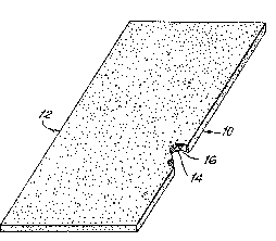
Referring now to FIG. 1 of the patent application
drawings, a first embodiment of new and improved, immiscible
liquid separation device representatively configured and
operable in accordance with the teachings of the apparatus
and method of our invention is indicated generally at 10.
Separation device 10 is constituted by liquid
separation means which comprise a separator piece 12 taking
the form of a generally rectangular strip 1~ of any suitable,
readily available material. This material ma~, for example,
be Mylar*or aluminum which are not highly hydrophobici or
may be a highly hydrophobic material, for example ~reflon*,
which may or may not be porous.
The separator piece strip 14 is thoroughly surface-
coated as indicated at 16 by a super-hydrophobic coating
material in the nature, for example, of Vellox llydrophobic
Coating as manufactured by M-Chem Corporation, 9 Bishop Road,
Ayer, Maryland 01432.
Super-hydrophobic coating materials of this nature
may be understood to be effective, when applied as a surface
coating to a subs~rate, to very substantially increase the
contact angle of a drop of aqueous liquid disposed thereon --
* Trade-marks
-13-
2622-~
~'"~ '
'` '' .. ,
-
. .
.
, ~ ` ' `
:~320137
and thus the hydrophobicity of the substrate-- to a value
well beyond the perpendicular. For example, such surface-
coating increases the aqueous liquid drop-substrate surface
contact angle from approximately 94~ to approximately 127
for Teflon, and from approximately 46 to approximately 150
for aluminum.
This feature of super-hydrophobicity as exhibited
by Vellox Hydrophobic Coating, and the manners in which this
coating material may be readily and thoroughly applied to
substrate materials of the natwre here under discussion, are
described in some detail in undated Technological Data Sheet
as published by M-Chem Corp. and entitled "Vellox 14." As
briefly described for purposes of this disclosure, super-
hydrophobic coating material application generally involves the
surface cleaning as required of the re.levant surface area of
the substrate, the application as by spraying of an appropriate
clear lacquer-type primer to the thusly cleaned substrate
surface area and, after a suitable drying period, the thorough
application, again as by spraying, of the Vellox coating material
thereover.
In addition to being intensely hydrophobic, super-
~hydrophic coating materials of the nature here under discussion
are known to be selectively "wettable" by a wide range of
fluorinated or perfluorinated hydrocarbon, or silicone, liquids,
to the substantial exclusion of aqueous liquids which are
immiscible therewith; and this phenomenon of selective
: :: :
:
-14-
2622-A
'
132~137
"wettability" of hydrophobie materials by these liquids to
the substantial exclusion of immiscible aqueous liquids is
discussed in some detail in United States Patent 3,479,141
issued November 18, 1969 to William J. Smythe,et al, for
"Method And Apparatus For Analysis" and assigned to the
assignee hereof.
United States Patent 3,479,141 also discloses the
use of this concept of selective "wettability" of hydro;?llobic
materials to minimize sample liquid carryover, e.g. the contam-
ination of a sueceeding aqueous sample liquid by the residue
of a precedincJ aqueous sample liquid, attendant automated,
successive aqueous sample liquid analysis. In accordance with
that patent disclosure, this is accomplished by the encapsulation
within an immiscible silieone liquid of the suecessive aqueous
sample liquids of a eontinuously flowing stream thereoE as the
same progresses through a fluorinated hydroearbon tubinc~ length;
with the silieone liquid funetioning as an isolation liquid
to isolate the aqueous sample liquids, one from the other, to
prevent contact and eross-contamination therebetweell, alld
functioning as an isolation liquid to selectively "wet" the
inner tubing length wall to the substantial exclusion of the
aqueous sample liquids thereby isolating the aqueous sample
liquids from that tubing length inner wall and preventing a
preceding aqueous sample liquid from contacting the same and
leaving a residue thereon for pick-up by and contamination of
a succeeding aqueous sample liquid.
-15-
2622-A_
,`,~'1 ~
:: . ,., . :
.: ' , ' ' ., - ' , . ' ' :
.
1320137
Other United States Patents which relevantly
disclose the application of this concept of selective
"wettability" of the hydrophobic materials by isolation
liquids to the substantial exclusion of immiscible aqueous
sample liquids for the minimization of sample liquid
carryover attendant automated, successive aqueous sample
liquid analyses are United States Patent 4,253,846 issued
March 3, 1981 to William J. Smythe, et al, for "Method ~nd
Apparatus For Automated Analysis of Fluid Samples" and
assigned to the assignee hereof, and United States Patents
4,121,466 and ~,357,301 as referred to hereinabove under
the "Description o the prior art;"~
~ second embodiment of new and improved immiscible
liqu.Ld separation device representatively configured and
operable in accordance with the teachings of the apparatus
and method of our invention i5 indicated generally at 18 in
FIG. 2. Separation device 18 is constituted by separation
means which comprise an uncoated separator piece 20 takincJ
the form of a generally rectangular strip 22 of any suitable,
readily available material which is inherently highly hydro-
phobic, for example Teflon, which may or may not be porous.
Under these circumstances, it will be immediately clear to
those skilled in this art that the hydrophobicity of the
uncoated separation device la of the en~odiment of FIG. 2
in terms of the contact angle which will be established
~ -16-
: 2622-A
.~
~ ' . ': ' ,
1320137
relative thereto by a drop of an aqueous liquid will not
be as high as that of the super-hydrophobic material-
coated separation device 10 of the embodiment of FIG. 1.
The cost, however, of the separation device 18, both in
terms of materials, and in terms of device fabrication,
will, in most instances, be lower than the cost of the
s-eparation device 10.
A third embodiment of new and improved immiscible
liquid separation device representatively configured and
operable in accordance with the teachings of the apparatus
and method of our invention is indicated generally at 24
in FIG. 3. In this embodiment, the liquid separation
device 24, which is illustrated as comprising the super
hydrophobic material-coated separator piece 12 of the
embodiment of FIG. 1, further comprises device locating and
handling means as indicated generally at 26 in FIG. 3.
Handling and locating means 26 take the form of a generally
rectangular, standard laboratory glass slide as indicated at
28; and the separator piece 12 is fixedly secured thereto
in any suitable manner, for example by an appropriate
:adhesive, to the upper surface of the glass slide 28 to
overlie the lower edge thereof as shown. As a result,
: handling and location of the separation device 24 without
req~lirement ~ for surface-contact with the separator piece
12, is rendered particu1arly convenient. Alternatively,
the separation dFvice 24 of the embodiment of FIG. 3 can
: : :
-17-
2622-A
132~137
take the form of the uncoated, inherently highly hydro-
phobic separator piece 20 of the embodiment of FIG. 2.
A fourth embodiment of new and improved immiscible
liquid separation device representatively configured and
operable in accordance with the teachings of the apparatus
and method of our invention is indicated generally at 30
in FIG. 4. In this embodiment, the liquid separator piece
as there indicated at 32 is in the form of a roll 34 of
any suitable, readily available flexible strip material
36, again for example Mylar, aluminum, or Teflon which may
or may be not be porous, which is thoroughly surface-coated
as indicated at 38 with a super-hydrophobic coating material
such as Vellox in the manner described in detail hereinabove
for the separator piece 12 of the embodiment of FIG. 1.
Alternatively, the separator piece roll 34 can be formed
from an uncoated, inherently hydrophobic material in the
manner of the uncoated separator piece 20 of the embodiment
of FIG. 2. Roll 34 i5 wound around a central spool as
indicated at 40.
: ~ first representative application of the new and
improved immiscible li~uid separation apparatus and method of
our invention to that effeat is illustrated in FIGS. 5, 6 and
~. In this application, which may for example be directed
to the separation of an aqueous blood serum sample liquid
from an immiscible isolation liquid of the nature discussed
hereinabove which will selectively "wet" a hydrophobic
-18
2622-~
~3~01~7
material to the substantial exclusion of that aqueous
sample liquid, and the subsequent analysis of the thusly
separated blood serum sample liquid with regard to a
specified constituent thereof, for example glucose,
the liquid separation device 24 of the embodiment of FIG.
3 is employed; and is retained and supported in the manner
of an inclined ramp in any appropriate manner by support
means 42 to form an angle of, for example, 60-75 with
the horizontal as represented by support surface 44.
A dry chemistry slide, for example the Fuji Glucose
Dry Chem 1000 Slide as manufactured by Fuji Photc Film Co. of
Asakashi-Saitamaken, 351, Japan, is indicated at 46 and
may be disposed at the sample application position of a
Fuji Dry Chem 1000 Analyæer. FIG. 5 makes clear that the
center of slide 46 is inessential vertical alignment with
the lower edge of separator piece 12.
Although essential dimensions and distances may,
of course, vary in accordance with the application to which
the~apparatus and method cf our invention are put, it may
be;noted that for the application of FIG. 5, a dimension
of lcm X 2 cm for the separator~piece 12, the extension
thereof about 2mm beyond ~he lower edge of the glass labor-
::
~: : atory slide 28, and the disposition of the lower edge of
the separator piece 12 a dlstance of 5-lOmm above the center
; of slide 46, have:respectively proven satisfactory.
~: : : `
~ 19-
2622-~
:~320~37
A standard, 20ul laboratory Pipettman is indicated
at 48 in FIGS. 6 and 7, and comprises a tip 50 of an
appropriately hydrophobic material, for example Teflon.
For blood sample serum analysis as described,
the tip 53 of Pipettman 48 is initially dipped in a
container (not shown) of the isolation liquid to result in
the l'wet~ing" of the lower portion thereof thereof with a
layer of the isolation liquid as indicated at 52 in FIG. 6.
The Pipettman tip 50 is then transferred to a container (not
shown) of the blood sample serum liquid of interest; and a
small quantity, for example lOul of the same aspirated
thereinto. This results in a globule of the blood serum
sample liquid as indicated at 54 in FI~. 7 being encapsulated
and retained within the isolation liquid layer 52 in the
Pipettmen tip 50; primarily as a result of the selective
"wetting" of the hydrophobic material of the tip by the
isolation liquid to the substantial exclusion of the aqueous
blood sample serum liquid.
The Pipettman 48 is then transferred to the position
thereof relative to the separation devlce 24 as depicted in
FIG. 5 and wherein ~he tip 50 is in essential vertical
:
alignment with the upper portion of the inclined separator
piece 12 and, for~example, disposed a distance of 5-lOmm
thereabove. The isolation liquid~encapsulated blood serum
sample liquid globule 54 is then released from the PipPttman
4S to fall freely onto the super-hydrophobic surface of the
;
-20-
2622-A
__
132~137
separator piece 12 and cascade down the same as illustrated
under the influence of the force of gravity. As this
occurs, the isolation liquid 52 is strongly attracted to,
spread across and sorbed by the super-hydrophobic
spearator piece surface to selectively "wet" the same to
the suhstantial exclusion of the aqueous blood serum sample
liquid 54; while the lat~er is strongly repelled by the
super-hydrophobic separator piece surface and falls freely
off the end of the inclined separator piece 12 as illustrated
onto the slide 46. Thus, substantially complete separation
of the aqueous blood serum sample liquid 54 from the isola-
tion liquid 52 is readily and effectively accomplished; and
slide 46 may immediately be advanced to the non-illustrated
analyzer for automatic analysis of the substantially isolation
liquid-~ree blood serum sample liquid 54 without adverse
isolation liquid-caused degradation in the accuracy of the
analysis results. Although the extent of isolation liquid-
caused degradation in the accuracy of blood sample liquid
analysis results varies widely in accordance with the partic-
ular;blood sample~ uid constituent of interest, and the
particular methodology~utilized to quantify the same, it has
been determined that, for glucose, errors in analysis
ac~curacy in the magn1tude of~over lS~ low can and do occur
when it is attempted to:analyze:the blood serum sample liquid
::by conventi~nal re~lectan~e spectroscopy analysis~means with-
out fir~s~t completely separating ~he same as described from
::
the isolation Iiquid. : :
~:
2622-A
::
~320~ 3~
The above-described p.rocess may then be repeated
as described for successive blood sample serum liquids of
interest, without sample li~uid carryover of consequence
due to the fact that each of the sample liquids is
substantially prevented by the isolation liquid layer
52 from contacting the wall of the Pipettman tip 50 and
adhering thereto for contamination of a succeeding sample
liquid, until separator piece 12 has been essentially satur-
ated by the isolation liquid to the extent that it can no
longer effectively separate the entirety of the same as
described from the blood sample serum liquid globule 54
of interest. As and when this is determined to have occurred,
it is, of course, a simple matter to replace the separation
device 24 with a fresh one for continuation of the blood
serum sample liquid analysis process.
Clearly, the separation device 10 of FIG. 1 or the
separation device 18 of FIG. 2 could be utilized instead of
the separation device 24 in the:arrangement of FIG. 5. In
such instances, the separator:pieces could readily be of
substantially greater dimension, for example 2cm X 8cm to
substantially increase the isolation li~uid adsorption
capacity thereof, and thus the number of isolation liquid-
encapsulated aqueous sample liquids as could be effectively
separated thereby~as~described; although these increases
would be counteracted with regard to the separation device
18 of FIG. 2 by the fact that the same is not coated with
:
-22-
2622-A
. . .
~``~ ~
~ ~2~13~
a super-hydrophobic CQating material.
A second representative application of the new
and improved immiscible liquid separation apparatus and
method of our invention to ~hat effect is illustrated in FIGS.
8 and 9- In this application, which may for example be
directed to the separation o successive isolation liquid-
encapsulated blood serum sample liquids from a continuously
flowing stream thereof --wherein the isolation liquid is
immiscible with the blood serum sample liquids and selectively
"wets" a hydrophobic material to the substantial exclusion
thereof-- and the subsequent successive analyses of the thusly
separated blood serum sample liquids with regard to a partic-
ular constituent thereo, for example sodium or potassium
through use o ion speci.ic electrode analysis methodology,
the liquid separation device 30 o FIG. 4 is employed, and
further includes a take-up spool 58 which is spaced as shown
from separation device supply spool 40, and which is operable
upon the driven rotation thereof to unwind and advance the
: ~ flexible separator piece 32 rom the supply spool 40. To
this effect, an electric drive motor as schematically indicated
: at 60 is provided; and the drive motor is mechanically
;connected as indicated to the take-up spool 58 for advancement
of the flexible separator piece 22 at a rate proportional ~o
:the speed of rotation of the drive motor 60.
Sampler and sample processing means are indicated
~ : -2~-
2622-~ :
:~320~3~
schematically at 62 in FIG. 8; and may, for example, take
the general form of those disclosed in United States Patent
4,121,466 wherein the same are operable to generate a
stream of isolation liquid-encapsulated successi^~e aqueous
blood serum sample liquids in a hydrophobic conduit as
indicated at 64, thereby minimizing carryover between those
aqueous sample liquids and significantly increasing the
accuracy of the sample liquid analysis results. This isolation
liquid-encapsulated sample liquid stream is illustrated in
FIG. 9 wherein the successive blood serum sample liquid segments
are indicated at 54a, 54b and 54c, the isolation liquid is
indicated at 52, and air-segments which operate to further
minimize sample liquid carryover are indicated at 66.
Sample analysis means are indicated schematically
at 68 in FIG. 8, and are operable in manner well understood
by those skilled in this art to automatically analyze the
blood serum sample li~uids as successively supplied thereto
with regard to a particular constituent thereof, in this
instance sodium or potassium as described hereinabove.
A system controller is indicated schematically at
70 in FIG. 8; and may, for example, take the form of an
appropriately programmed microprocessor device. Controller
70 is electrically connected as indicated by lines 72, 74
and 76 to ech of sampler and sample processing means 62,
sample analysis means 68 and drive motor 60 to control and
synchronlze the respective operations thereof.
--2~-
2622-A
. _ .
:~32~37
With the outlet end 77 of the sample liquid
supply conduit 64 disposed as sho~m in FIG. 8 slightly
above and in essential vertical alignment with the
center of the lower portion of the exposed length of the
flexible separator piece 32 as extends between supply spool
40 and take-up spool 58, it will be clear that as each
isolation liquid-encapsulated aqueous blood serum sample
liquid segment 54 is flowed in turn from the conduit outlet
end 77, the same will fall freely therefrom onto the super-
hydrophobic surface of the spearator piece 32 and cascade
down the same as illustrated under the force of gravity.
As this occurs, the isolation liquid 52 is strongly attracted
to, spread across and sorbed by the super-hydrophobic
separator piece surface to selectively "wet" the same to
the substantial exclusion of the aqueous blood serum sample
liquid segment 54; while the latter is strongly repelled
by that super-hydrophobic separator piece surEace and falls
freely off of the effective "edge" thereof as indicated at
80 into the sample liquid analysis means 68 for analysis
as described. Thus, substantially complete separation of
the aqueous blood serum sample liquid segments 54 from the
isolation liquid 52 is readily and effectively accomplishedi
: and meaningful degradation thereby in the accuracy of the
ion selective electrode blOod serum sample liquids analysis
results effectively prevented.
Shield means are schematically indicated at 82 in
FIG. &, and are dispbsed as shown to underlie that portion
. ~25-
2622-A
__
of the flexible separator piece 32 as is wound around
take-up spool 58 immediately to the right of separator
separator piece "edge" 80, thus insuring that any sorbed
isolation li~uid 52 as may tend to separate and fall
from the separator piece beyond "edge" 80 in the counter-
clockwise direction as seen in FIG. 8 upon the continued
advancement of the separator piece will be effectively
prevented from falling into contact with the sample liquid
analysis means 68.
System controller 70 is programmed to activate
drive motor 60, and thus advance flexible separator piece
32 at a rate careully predetermined to avoid isolation
liquid saturation of the relevant lower portion o~ the
exposed length of the separator piece, thereby insuring that
the same remains fully effective to the isolation-blood
serum sample liquid separation task at hand for the entire
series of the blood serum sample liquid segments of interest.
This advance may be continuous, or may be periodic.
As an alternative to ~he representative application
of FIGS. 7 and 8, it will be clear that the liquid separation
device 3C may also find use in an application as illustrated
by FIGS. 5, 6 and 7 wherein the isolation liquid-encapsulated
sample liquids are manually sequentially applied thereto. In
: : such~ instance, advancement;of the flexible separator piece
32 could also be accomplished manually, most probably on a
periodic basis as and when determined to be required.
-26-
262~-
~201 37
Referring now to FIGS. 10 and ll of the drawings,
the same will be seen to depict an application of the immiscible
liquids separator device of our invention, for example,
separator device 10 of FIG. l, wherein the device is maintained
essentially level rather than inclined. For such application,
the isolation liquid encapsulated aqueous sample liquid globule,
as again indicated at 52 and 54 in FIG. lO, is formed and
disposed in any applicable manner, again for example by use
of the Pipettmen 48 as illustrated and descxibed in some detail
hereinabove with regard to FIGS. 5, 6 and 7, upon the upper
surface of separator device 10. In this instance, however, the
essentially level orientation of the separator device 10 will
result in the maintenance of that isolation liquid encapsulated
aqueous sample liquid globule on tha~ upper separator device
surface; initially essentially as depicted in FIG. 10. Of
course, the selective wettability of the super hydrophobic
coating 16 on the upper surace of the separator device 10, to
the substantial exclusion of the:aqueous sample liquid, will as
described in some detail hereinabove very quickly result in the
solatlon liquid 52 being sorbed by that surface coating and
effectively separated from the aqoeous sample liquid 54, thus
: : ~leaving the aqueous sample liquid~globule substantially separated
from the encapsulating~isolation liquid and standing alone as such
on the super hydrophoblc upper surface of the separator device lO
as:illustrated in FIG. ll. :
:
~ -27
2622-A
::
132~1~7
With the thusly substantially separated aqueous sample
liquid globule 54 disposed as shown in FIG. 11 on the upper
surface of the separator device 10, it will be understood by
those skilled in this art that the globule may ~e readily and
effectively removed therefrom, at least in substantial part,
for example through appropriate manipulation of a Pipettman or
like device, for transfer for additional sample liquid processing
and or analysis as the case may be~ Alternatively, the separator
device 10 with the substantially separated sample liquid globule
54 disposed thereon as illustrated in FIG. 11, may be readily
transferred as such, either manually or automatically, to an
appropriate sample liquid analysis device, not shown, for example
a colorimeter, for analysis of the sample liquid globule 54 in
situ on the separator device 10.
For use of the super hydrophobic material coated
separator device 10 of FIG. 1 for the invention application of
FIGS. 10 and 11, a preferred material for the separator device
strip 14 would be al~lminum which, when surface coated with
Vellox, results in a particularly advantageous aq~eous sample
liquid globule contact angle as high as 150 as set forth
hereinabove. Alternatively, the separator devices 18, 24 or
30 of FIGS. 2, 3 and 4 may be utilized for the invention
application of FIGS. 10 and 11 by the respective dispositions
of the same in essentially level rather than inclined positions,
and retention of the substantially separated aqueous sample
-28-
2622-A
~ ` -
~ 320137
liquid globule 54 thereon as described in each instance.
With more specific regard to the use of the
separator device 30 of FIG. 4 for this invention application
wherein the relevant hydrophobic separator device surface is
maintained essentially level, a representative configuration
thereof will be seen to be illustrated by FIG. 12, and to include
the supply spool 40, take-up spool 58, and drive motor 60
operat.ively connected to the latter, all in manners described
in detail hereinabove with regard to FIG. 8, thereby again
providing for advancement of flexible separator piece 32 at
a rate carefully predetermined to avoid isolation liquid
saturation of the relevant surface of that separator piece.
FIG. 12 further includes the representative schematic depiction
of sampler and sample processor 62, and sample supply conduit
6~, to illustrate the capability o~ the separator device 30
with the relevant hydrophic device surface maintained essentially
level to receive isolation liquid encapsulated sample liquid
globules 52, 54 on an automated feed basis; and also illustrates
the substantial separation of the sample liquid globule 52 from
the encapsulating isolation liquid globule 54 on the essentially
level relevant hydrophobic surface of the spearator device 30 as
the latter is advanced to the left as seen in FIG. 12.
FIG. 13 lllustrates a representative application of
the separator device 30 of FIGo 12 to an automated sample liquids
analysis system; and, in this re~ard, will be seen to include
-29-
2622-A
-
132~137
sampler and sample processor, drive motor, and automated
sample liquids analysis device, as respectively schematically
indicated at 62, 60 and 68, and a system controller as
schematically indicated at 70 and electrically connected
to sampler and sample processor 62, drive motor 60 and sample
liquids analysis device 68 as indicated by lines 72, 76 and
74 to synchronize and control the respective operations thereof
in the manner described in some detail hereinabove with regard
to FIG. 8. In this separator device application, the automated
sample liquids analysis device may, or example, take the form
of a colorimeter; and, to that effect, is illustrated in FIG.
13 as comprising a llght source 90 and a photo-detector 92
disposed as shown to opposite sides of the essentially level
flexible separator device portion in such manner that the light
energy beam from source 90 will pass through the substantially
separated sample liquid globules 52 prior to the impingement on the
active surface of the photo-detector 92 as those sample liquid
globules are advanced in turn with the separator device 30 ~rom
the right to the left as seen in FIG. 13. Accordingly, it will
be clear to those skil.led in this art that highly accurate
automated successive sample liquids analyses of the substantially
separated sample liquid globules will be advantageously provided
by the sample liquids analysis system of FIG. 13, substantilly
: without degradation in that accuracy by the isolation liquid.
A fifth embodiment of new and improved immiscible
liquid separation device representatively configured and
-30-
26
~320~ 3~
operable in accordance with the teachings of our invention is
indicated generally at 94 in FIG. 14, and comprises a generally
circular separator piece 96 of any appropriately liquid-
permeable material, for example a mesh material as illustrated.
The mesh material of the separator piece 96 may, for e~ample,
take the form of a nylon mesh which is surface coated with
Vellox as described hereinabove to render the same super
hydrophobic. Alternatively, the mesh material may be Vellox-
coated Mylar, aluminum or Teflon, which may or may not be porous,
to in any event render the same super hydrophobic; or may taXe
the form of an uncoated, inherently highly, but not super, hydro-
phobic material such as Teflon which again may or may not be
porous. In addition, it will be clear to those skilled in this
art that the essential characteristic of liquid permeability for
the separator piece 96 can readily be provided by configurations
thereof other and different than a mesh, for example a generally
circular pi.ece of any of the above mentioned materials with a
large plurality of appropriately small diameter holes formed
therein, not shown.
In use of the separator device 94 of FIG. 14, an
isolation liquid encapsulated sample liquid globule 52, 54 is
placed, as by dropping, generally centrally of the essentially
level separator piece 96 as illustrated by FIG. 15. As this
occurs, the isolation liquid 52 which selectively wets the
hydrophobic mesh material surfaces of the separator piece 96 to
the substantial exclusion of the aqueous sample liquid 54, will
very ~uickly be sorbed by those surfaces for substantial retention
2622-A
1320~ 3~
on and in the liquid-permeable separator piece against the
influence of the force of yravity as illustrated by FIG. 16.
Concomitantly, and as also illustrated by FIG. 16, the aqueous
sample liquid 54 which is substantially excluded as described
from the wetting of these hydrophobic mesh material surfaces,
will pass very quickly through the liquid-permeable separator
piece 96 under the influence of the force of gravity to fall
freely therefrom for collection in any appropriate device or
instrumentality as indicated schematically at 98 in FIG. 16.
Accordingly, substantial separation of the aqueous sample
liquid from the isolation liquid is rapidly and effectively
accomplished. Although representatively depicted and described
as generally circular for conservation of separator piece material
in accordance with the generally spherical configuration of the
isolation liquid encapsulated sample liquid ~lobule 52, 54, it
will be clear that the separator piece 96 may alternatively be
of generally rectangular strip-like configuration, and may also
be fabricated in the form of a flexible roll.
A representative application of the separator device
94 of FIG. 14 of our invention in combination with a samplQ liquid
reaction device is illustrated in FIGS. 17 and 18, and comprises
the disposition and retention, as by a suitable adhesive, of the
separato~ piece 96 in the like-sized sample liquid aperture 100
of a dry chemistry slide 102, again for example the Fuji dry
chemistry slide as discussed hereinabove. Although not, per se,
forming any part of our invention, it will be understood by those
skilled in this art that the dry chemistry slide 102
-32-
2622__
132~13~
comprises a housing 104 of any appropriately inert material
having the generally rectangular, chemically reactive slide
element 106 sandwiched therewithin as best seen in ~I5. lg.
The sample liquid access aperture 100, and an aligned sample
liquid analysis aperture 108 are formed as shown in the housing
104 to respectively extend ~o opposite sides of the reactive
slide element 106, thereby providing access to that element
for both sample liquid introduction thereto and sample liquid
analysis following appropriate sample liquid~reactive element
reaction. Apertures 100 and 108 are generally of 3/8" diameter.
In use, the isolation liquid encapsulated sample liquid
globule, not shown, is placed as by dropping generally centrally
of the slide-mounted separator piece 96 in the manner illustrated
for the same by FIG. 15. As this occurs, the isolation liquid
will be substantially sorbed by the hydrophobic separator piece
surfaces and retained thereby substantially out of contact with
the chemically reactive slide element 106. Concomitantly, the
aqueous sample liquid will pass through the separator piece 96
under the influence of the force of gravity for flow into contact
~nd combination with the reactive element 106 which underlies the
separator piece 96. Thus will be clearly understood by those
skilled in this art that the essential functions of the substantial
separatlon of the aqueous sample liquid from the isolation liquid,
and the introduction of the former to the chemically reactive
dry chemistry slide element, are effectively combined to signifi~
~ant advantage in accordance with the teachings of our invention.
-33-
2622-A
1~201~7
By all of the above is believed made clear that
the new and improved apparatus and method of our invention
will function in full accordance with the stated objPcts
thereof to readily, effectively and inexpensively accomplish
the virtually immediate and complete separation of immiscible
liquids to distinct and spaced locations without contact
therebetween.
Although disclosed hereinabove by way of represen-
tative examples as applied to the separation of blood serum
sample liquids from encapsulating, immiscible isolation
liquids attendant blood serum sample liquid analysis, it
will be immediately clear to those skilled in this art that
the method and apparatus of our invention are by no means
limited to such liquids, or to analytical application. In
additiont it is not required for satisfactory application of
the. apparatus and method of our invention that one of the
liquids be encapsulated in the other of the liquids. Too,
the term "liquid" as used in this specification can~ of
course, apply to more than one of the same) for example,
a liquld mixture.
Various changes may, of course, be made in the
hereindisclosed embo2iments of the apparatus and method of
our invention without departing from the spirit and scope
.
thereof as defined in the appended claims.
-34-
2622-A