Note : Les descriptions sont présentées dans la langue officielle dans laquelle elles ont été soumises.
t32~s~3j
ntenna system with ad~ustsble beam width and beam orientation.
The invention relates to an antenna system provided with at least
one active radiation source and a reflective surface which is
located in at least one part of the radiation generated by the
active radiation source.
The reflector in conventional antenna systems has a fixed contour to
generats a beam with a certain width snd oriantation. This
construction however has the disadvantage that the antenna sys~em is
lim~ted in its application: beam width and beam orientation remain
fi~ed. Such antenna systems are usually also very bulky. ~oreover,
such antenna systems are unsuitable for application in a so-called
3D radar, in which also the alevation of a target is determined.
The invention has for its object to provide an antenna system whose
beam parameters are very rapidly ad~ustable while the antenna
characteristics, such as side lobes and grating lobes, are
particularly favourable. The speed at which the beam parameters of
the antenna system can be varied is so high that the antenna system
is suitable for use in a 3D radar applied as a tracking radar for
tracking targets. The antenna system is however also suit~ble for
use as a rapidly scanning search radar.
L
According to the ~nvention the antenna system is for that purpose
provided with at least one active radiation source and a reflective
surface which iQ located in at least a part of the radiation with a
wavelength ~ generated by the active radiation source, where the
reflective surface is provided with a ~umber of individually
ad~ustable plates for the generation of at least one beam, where the
ad~us~ing means are suitable for translating the plates with respect
to eachother, and where a plate's dimensions are in the order of
~he wavelength ~.
~k
I , , .
,: ,;,. . , -, :
- , - , ~ ~ .';: . i, . :
~2~
As a result o~ the fact that the reflective surface is provided with
individual plates, a multifunctional antenna system of a limited
voiume is created. According to the invention the plates can be
arranged in such a way that a beam is obtained having the required
orientation and width. ~oreover, an individual plate can be shifted
almost ~ touards the direction of the impinging radiation (with
wavelength ~) without changing the phase of the reflected radiation.
The individual plates thus enable the construction of an antenna
system of which the contour, created by the individual plates, forns
a practically f1at surface, of which the normal is parallel to the
mean direction of impinging radiation originating from the active
radiation source and whera the distance between an individual plate
and the flat surface does not exceed ~.
Because a plate has dimensions in the order of the wavelength ~, the
potential dynamic qualities of the antenna system will be very high.
As a result, the pla~es are very light and can thersfore be
rearranged very quickly. Because the plates are so small, it is
especially advantageous according to the lnvention to make the plates
translatable with respect to each other. It is after all particularly
attractlve to provide one plate with only one linear actuator, in
view o~ the dimensions of the plate. However, it is surprising and
completely unexpected that, when & plate is small with respect to
the wavelength, while a plate cannot be rotated (no tilt) but ~ust
translated, an antenna system is obtained whose beam parameters can
be ad~usted very accurately, without in~erference of side lobes
and/or grating lobes. Up till now it was assumed that antenna systems
provided ~ith plates having dimensions in the order of the waveleng~h
cannot generate a good bsam without interference rom side lobes and
grating lobes.
An antenna sys~em, known ~rom IEEE Transactions on Antennas and
Propagation, ~ol. AP-14, no. 5, September 1966 (US), page 559-560, ~s
,,,., ,. , , , : . : -
.. , :
., .: :, ; -
: .
1~2~ 3
provided ~ith plates which can be translated as well as rotated (tilt
is ad~ustable). The tilt is ad~ustable per plate because a plate has
a cross section of several metres, i.e. hundreds of times more than
the wavelength ~. Such an antenna system can therefore be compared to
an antenna system whose cross-section is shown in Fig. 2. An antenna
system according to the invention ho~ever is shown in Fig. 3, from
which it is clear that here a contpletely different antenna is
concerned from that of Flg. 2. Because of the size of the plates,
such an antenna system requires some 10 seconds to adjust the beam,
making it unsuitable for the purpose for which the antenna system is
applied accordlng to the invention. An antenna system according to
the invention tFig. 3) therefore has an ad~ustment time which is less
than 5 ms.
According to the lnvsntion, the antenna system is provided with means
to independently ad~ust the plates for the purposa of orientating
the antenna beam. This allOws the construction of a dynamic antenna
system having the above-mentioned advantageous characteristics. By
ad~usting and read~usting the individual plates using the ad~usting
means, an antenna system is obtainad having a dynamically
orientstable beam and dynamically ad~ustable beam width. This is
particularly important for appllcation in a 3D radsr tracking a
target by directing the beam and ks~ping 1~ flxed on the target.
Another development known from radar technology is the so-called
phased-array antenna. The present ln~ention however concerns an
antenna comprising a number of active elements. Beamforming in a
desired direction is achievad by controlling the position of a
sufficient number of active elements having a proper mutual phase
relationship. The disadvantage of such a system however is that it
is very expensive due to the large number of ac~ive elemants. The
antenna system according to th~ invention requires only ona active
element, resulting in an enormous cost reduction, while the
perform~nce is able to meet the highest requirements.
1 32~2~
I~ is known from US-A 4,090,204 to use plates which are ad~ustable
only across a fraction of the wavelength, applying an
"electromagnetic lens". However, tha disadvantage of this method is
that side lobes are generated, while the accuracy with which a beam
can be orientated is absolutely insufficient for use as e.g. a 3D
tracklng radar.
If two ad~acent surfaces have been translated with respect to each
other across a relatively long distance, the first surface may cast
a shadow on the second surface as regards the radiation generated by
the active radiation source.
According to the lnvention, shadowing can also be prevented by
applying strips of metal between ad~acent plates, wh~ch strips are
orientated practically parallel with the normal of the relevant
plates and which extend beyond the plates in the direction of the
impinging beam from at least one active radiation source. The plates
are now posltioned as it were inside a ~aveguide, where a plate
serves to close off the waveguide. Shadowing therefore does not
occur here. The dynamic properties of the antenna system according
to the invention can even be increased if the antenna system is
provided with a reservoir filled with a medium, where the plates are
located inside the reservoir, and the walls of the reservoir are
suitable for letting through electromagnetic waves. As a result of
2~ the presence of the medium, having an electric permeability ~, the
wavelength ~ ~ill be reduced in the medium by a ~actor ~. The
advantage of this is that the maximum required translation distance
of an individual pla~e is reduced by a factor ~. This, however,
results in a considerable increase of the mobility of the generated
beam
According to the invention it is also possible to generate more than
one orientatable beam. For this purpose, the plates can be adjus~ed
~: .. ' ! . '.. . ~:, `
:- '' ` . ' '' -
` ' ' :'
' ~ ;' ` ~ ' '
`. . , ~ '
, ' '
32~2~
24005-164
in such a way that p antenna subsystems (p = l, 2, 3, ...) are
created to generate p orientated beams, where the plates belonging
to an antenna subsystem comprise at least one group of plates.
According to a special embodiment of the invention the
plates are circular and arranged in a compact stack. Since the
gaps between the different sections is minimised, the sections, if
the plates are sufficiently small, will behave like a so called
Faraday shield, resulting in an apparently closed reflective
surface for the impinging radiation.
In summary, according to one broad aspect of the
invention there is provided an antenna system comprising: an
active radiation source having a wavelength ~ ; a substantially
flat, contoured surface formed by a plurality of separate and
independently adjustable adjacent reflecting plates having
transverse dimensions on the order of the wavelength ~ positioned
for reflecting the radiation and forming at least one radiation
beam; and adjusting means for dynamically translating the plates
with respect to each other during operation of the antenna system,
thereby determining the antenna beam pattern.
According to another broad aspect, the invention
provides a reflecting surface for use with an antenna system
having an active radiation source with a wavelength ~ , in which
the reflecting source is a substantially flat, contoured surface
formed by a plurality of separate and independently adjustable
adjacent reflecting plates having transverse dimensions on the
order of the wavelength ~ positioned for reflecting the radiation
and forming at least one radiation beam.
'
'',, : . , ' ; '
` :, .
:, . `, : ' '`
~32~2~
24005-164
The invention will now be described in more detail with
reference to the accompanying figures, of which:
Fig. l represents a cross-section of a conventional antenna
system;
Fig. 2 represents a cross-section of an antenna system as an
illustration of the principle of the invention;
Fig. 3 represents a cross-section of a dynamic embodiment of
an antenna system accordlng to the invention;
Fig. 4 represents a second embodiment of an antenna system
according to the invention;
Fig. 5 represents a third embodiment of an antenna system
according to the invention;
Fig. 6 represents a cross-section of a fourth embodiment of
an antenna system according to the invention;
Fig. 7 represents a first embodiment of a means for adjusting
a plate;
Fig. 8 represents a second embodiment of a means for
adjusting a plate;
Fig. 9 represents a third embodiment of a means for adjusting
a plate;
Fig. 10 represents a fifth embodiment of a part of an antenna
system according to the invention.
5a
~: , . .
, - ~ .,
~32~
Fig. l shows ~ feedhorn 1 in a cross-section of a simple
conventional antenna system. Feed~orn l is positioned opposite a
reflective surface 2 and generates electromagnetic waves having a
wavelength ~ in the direction of surface 2. In case of radar
5 applications, a receiving horn may also be used for the reception of
echo signals reflected by an ob~ect. The contour of the reflective
surface is such that after reflection against surface 2 a
practically parallel or some~hat diverging beam 3 is obtained. For
this purpose, the surface may for instance have an almost parabolic
contour, where the feedhorn is situated in the focal area,
preferably the focal polnt of the contour. After reflection, the
phase difference ~ a ~ ~b between outgoing beams a and b in the
indicated directlon appears to be ~ ~ 0, as a result of which
these beams amplify eachother in this direction. It will be clear
that a similar beam is obtained when the phase difference
~ a ~ ~b - ~ k x 360 (k - 1, 2, ...).
This implies that reflection points ~a and ~b can be shifted ~ith
respect to sach other across a distance of + k x ~ ~k ~ 1, 2, ...)
in the direction of the impinging beam without changing the
reflective properties of the reflective surface. In Fig. 2 the
reflector is provided with five individual plates 2.i (i - 1, 2,
..., 5). Plates 2.2 and 2.4 have been shifted in the direction of
the im~inging beam across a distance ~ uith respect to surface 2,
while plates 2.1 and 2.5 have bean shifted in the direction of the
impinging beam across a distance ~ (see fig. 2). The phase
relationship between the outgoing beams after reflec~ion has ~hus
been main~ained. ~ plate 2i ~i ~ 1, ..., 5) in this e~3mple shows
along its surface a phas¢ shift of ~ 0 ~ith respect ~o the
incoming beam. Thus the volume of rerlective surface 2 has been
considerably reduced: the "thlckness" D of the reflective surface
(see Fig. 2) equals at the most ~, so the reflective surface is
pract~cally flat. The reflactive surface of Fig. 2 is however not
suitable for a dynamic construction when high speeds are required.
~: , .
::
~ 3 ~
This is caused by the plates being relatively large and,
consequently, slow.
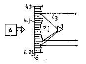
In Fig. 3 the reflective surface of Fig. 2 has been replaced by a
reflective surface according to a dynamic embodiment of the
invention. Reflective surface 2 has for this purpose been provided
with a large number of plates 2.~ 1, 2, ..., 21). Plates 2.
have been provided with adJusting means 4.; (~ - 1, 2, ..., 21),
mounted on a support 5 with which a plate 2.~ can be moved up and
down. The direction of movement in this example is perpendicular to
support 5.
In Pig. 3, plates 2.~ have been arranged in such a way that they
follow the contour of Fig. 2 and thus generate a beam according to
the antenna system of Fig. 1. The plates 2.; (; - 6-16) form a
group of which the phase difference ~tp between plates is Q~ < 180.
Other groups are formsd by plates 2.J (~ - 1,2), plates 2.J
(J 3-5), plates 2.~ 17-19) and plates 2.; (~ ~ 20,21).
The plates at the edges of two ad~acent groups (e.g. plates 2.16 and
2.17) however, are plates of which the phase difference ~ ~ 180.
This has the advantage that ad~usting means 4.~ only require an
ad~ustment range of not more than ~, which squals a maximum phase
difference of ~ 3 180~. It is of course also possible to arrange
the plates in such a way that within a group of plates, a phase
difference ~ occurs of appro~i~ately n.180~ ~n = 2, 3, .. ), while
the ph~se dif~erence between two ad~acent plates belonging to
different groups amounts to approximately n.l80. The difference in
distance b0tween two ad~acent plates belonging to different groups
then amounts of n.~, while the difference in distance between
ad~acent plates withi.n a group of plates, when the number of plates
is sufflciently high, is lower than n.~. The plates of Fig. 3 have
a cross s~ction lower than ~ to make them sufficiently light. As a
result, the plate can be rapidly translated with respect to each
: , ~ : :,
, , ~, , :
- :, :~ .
. : ~ : : ,.
1 3 ~
other, incressing the dynamic qualities. The size of a plate is in
the order of 5 mm.
The groups of plates are preferably formed in such a way that n-l.
This is particularly advantageous when by means of control means 6,
controlling the adjusting means, the reflective surface 2.~ is
constantly adapted to orientate and reorientate the reflected beam.
~oreover, the divergency of the beam may be changed by rearranging
the plates with respect to each other. Since n~l the maximum
di~tance to be covered by the ad~usting means in positioning the
plates with respect to each other is only ~A. In this way, the
amount of time requlred to direct a beam is minimised and tha
dynamic qualltles are maximls2d. An antenna system accoxding to the
invention is capable of orientating a beam in the re~uired direction
within 10 ms.
If the direction of the antenna bsam generated by means of the
antenna system of Pig. 3 is gradually changed, this is realised by
moving the plates with respect to each other in such a way that the
contour they form, as indicated in Fig. 3, propagates visually li~e
a travelling wave parallel with the surface of support 5. Thls
causes a relatlve movement of the feethorn in the focal area formed
by plates 2.~, resultlng ln a beam whlch changes direction. If the
plates are arrangled ln a straight line, the beam can be controlled
in one tlrection only, e.g. ln azlmuth ln case the antenna system ls
used as a search :radar to perform a sweep across an azimuth width of
for instance 90. The beam width and slevation can then be fixed by
giving plates 2.~ a certain dimension vertically and, if necessary,
applying for instance a parabolic contour. Fig. 4 shows such an
antenna system, using the same references as Fig. 3.
By means of four similar perpendicularly positioned antenna systems,
a sweep can be made across 360. Due to the fact that they are flat,
1 3 2 ~
the four antenna systems csn be used for naval applications, mounted
to the walls of a ship.
Application in 3D radars requires an antenna beam that can be
orientated in azimuth and in elevation. A possible embodiment of
such a reflective surface is shown in Fig. 5.
In Fig. 5, the plates 2.m.n are arranged according to a matrix
structure (J ~ m,n ~ 1, 2, ..., 21). The plates in this figure are
circular and arranged with raspact to each other by means o~ a most
compact stacking. As a result, the gaps between plates are
minimiset, thus homogenising the rePlective surface. The dimension
of a gap can be such that it behaves like a Faraday shield, as a
result of which this gap appears not to exist for implnging
radiation. A plate can also be according to other embodiments, such
as a rQgular n-angle (n 2 3~. By arranging plates 2.m.n,
horizontally as well as vertically in accordance with a certain
antenna contour, a beam may be directed in azimuth as well as in
elavation.
Fig. 3 shows a side view of a horizontal or vsrticsl row of pla~es
of Fig. 5.
The feedhorn in Fig. 3 does not particularly need to be sltuated in
the corresponding focal point in case the plates form sn eifecti~e
reflector with a parabolic contour. An orientatablP beam is also
generated if khe feed-horn is located somewhere else in the ~ocal
area. It is also not especially necessary tha~ the focal area be
parallel to support 5. This opens ~he possibility to place the
feedhorn next to the beam going out af~er reflection. Fig. 6 shows a
simplified cross section of such a system with the accompanying
radiation path.
. .. , ,. . ,. , ., . ~ . ,. ~ . .............. - -
t ' `, ,:
1 32~2~
A more cost-effective embodiment of the antenna system according to
the invention is obtained if a number of plates is not present, e.g.
the even-numbered plates 2.m.n and 2.~ respectively. It has been
proven that the performance of such an antenna system deteriorates
only very slightly.
Fig. 7 ~hows a possible embodiment of an ad~usting means (4.~ or
4.m.n) for a plate (2.J or 2.m.n). The ad~usting means is provided
with a coll 7 and a magnetic core 8 incorporated in the coil.
~agnetic core 8 is connected to a housing 10 by means of a spring 9.
A plate 2.~ is connected on the outside to an extension of magnatic
core 8, which is partly positioned outside housing 10 through
feedthrough aperture 11. Nith the supply of control signals
generated by control means 6, the magnetic core can be moved towards
a state of equilibrium in which the resilience of the spring and the
Lorentz force of magnetic core 8 and coil 7 compensate aach other.
Another embodiment of an ad~usting means (4.J or 4.m.n) for a plate
(2.~ or 2.m.n) is shown in Fig. 8. ~le ad~usting means is provided
with a coil 7 and a magnet 8 incorporated in snd around the coil.
Magnet 8 has a fixed connection with houslng 10. Spindle 12 is
movable inside the magne~. The spindle is connected to housing 10
via a spring 9. One end of coil 7 is connacted to spindle 12. Wi~h
the supply of control signals generated by control means 6, ~he
magnet can be moved towards A state o~ equilibrium in which the
resilience of the spring and the Lorent~ force of magnet 8 and coil
7 compensate each other. To decrease the friction between spindle 12
and m~gnet 8, a high- requency signal can be supplied additionally
to ~he coil.
An alterna~ive embodiment of an ad~usting means is shown in Fig. 9.
In ~his embodiment a cilinder 13 is provided with a piston 14,
.
,, ,; ,
' ' .,
1 3 ~ 3
which can be brought in an e~treme position by means of a spring 15.
Piston 14 is connected to plate 2.~ via a bar 16. By supplying air
via duct 17, which for this reason is connected to control means 6,
the cilinder and thus plate 2.~ is brought into the required
position.
The phase ~ump of approxlmately n x ~2~ (n = 1, 2, ...) between
ad~acent plates of different groups may create the adverse effect of
shado~ing. To solve this problem, according to the invention
reflective surface 2 can be provided with strips of metal placed
between the plates and forming a screen work 18. Fig. 10 shows a
part of such an an~enna syst~m. The plates, in any possible
position, are flush with the screen, so the plates are located as it
were inside a waveguide. Due to the waveguide effect of screen 18,
shadowing is prevented: the impinging radiation moves via the walls
of screen 18 to a plate 2.m.n and vice versa after reflec~ion on the
plate.
As mentioned before, the range of the adJusting maans ~ust be at
least ~. When the frequency of the radiation generated by feedhorn
1 is decreased, the ad~ustment range will have to increase. As a
result, the average t~me within ~hich a plate can be brough~ to the
required position increases. According to a speci 1 embodiment of
the invention, to achieva this, th~ antenna system is provided with
a reservoir within which the reilection surface ls placad. The
reservoir is filled with a madium having a high electrical
permeability ~. As a result, the wavelength o~ ~he impinging and
reflected radiation within the medium ~ill decrsase by a factor ~,
while the 4requency remains the same. Because the wavelength has
decreassd by a factor ~ he range of the ad~ustment
means will also decrease by a fac~or ~. The advantage of this is
that ~he avsrage time required to position a plate decreases.
:, , , i ~
.
~ ~2~ 2~
12
As a result, the antenna system bacomes more dynamic. Depending on
the viscosity of the medium however, the dynamics of the antenna
system can decrease as a result of friction between the medium and 8
moving plate. For this purpose, a plate (2.~or 2.m.n) may also be
provided with at least one feedthrough aperture 19 (see Fig. 10),
where, when a plate moves, the medium can flow through the
throughput aperture freely, so that the average friction will
decrease. This throughput aperture is preferably smaller than ~ to
prevent that the reflective properties of a plate are changed by the
presence of the throughput aperture.
In accordance with the antenna system according to the invention, it
is also possible to generate more than one beam. In that case the
antenn& system comprises p (p ~ 2, 3, ...) antenna subsystems. For
this purpose the reflective surface of Fig. 5 can for instance be
divided into p~4 sectors A, B, C and D, where the plstes of a sector
are positioned in such a way that-they generate a beam independently
of the plates of the other sectors.
.~ , . . . . . . .