Sélection de la langue

Search

Sommaire du brevet 1321775 

Énoncé de désistement de responsabilité concernant l'information provenant de tiers

Une partie des informations de ce site Web a été fournie par des sources externes. Le gouvernement du Canada n'assume aucune responsabilité concernant la précision, l'actualité ou la fiabilité des informations fournies par les sources externes. Les utilisateurs qui désirent employer cette information devraient consulter directement la source des informations. Le contenu fourni par les sources externes n'est pas assujetti aux exigences sur les langues officielles, la protection des renseignements personnels et l'accessibilité.

Disponibilité de l'Abrégé et des Revendications

L'apparition de différences dans le texte et l'image des Revendications et de l'Abrégé dépend du moment auquel le document est publié. Les textes des Revendications et de l'Abrégé sont affichés :

  • lorsque la demande peut être examinée par le public;
  • lorsque le brevet est émis (délivrance).
(12) Brevet: (11) CA 1321775
(21) Numéro de la demande: 1321775
(54) Titre français: ELEMENT DE FERMETURE A CAPE
(54) Titre anglais: CLOSURE WITH SNAP TYPE HINGE
Statut: Périmé et au-delà du délai pour l’annulation
Données bibliographiques
(51) Classification internationale des brevets (CIB):
  • B65D 47/08 (2006.01)
(72) Inventeurs :
  • FILLMORE, WILLIAM E. (Etats-Unis d'Amérique)
(73) Titulaires :
  • OWENS-ILLINOIS CLOSURE INC.
(71) Demandeurs :
  • OWENS-ILLINOIS CLOSURE INC. (Etats-Unis d'Amérique)
(74) Agent: GOWLING WLG (CANADA) LLP
(74) Co-agent:
(45) Délivré: 1993-08-31
(22) Date de dépôt: 1988-09-29
Licence disponible: S.O.
Cédé au domaine public: S.O.
(25) Langue des documents déposés: Anglais

Traité de coopération en matière de brevets (PCT): Non

(30) Données de priorité de la demande:
Numéro de la demande Pays / territoire Date
155,894 (Etats-Unis d'Amérique) 1988-02-16

Abrégés

Abrégé anglais


16275
CLOSURE WITH SNAP TYPE HINGE
Abstract of the Disclosure
A closure with a snap type hinge cap comprising a
first part adapted to interengage with the open neck of a
container and a second part forming a cap. Each of the first
and second parts comprises a base wall and a peripheral skirt.
A pair of hinges extends between the skirt of the first part
and the skirt of the second part to hinge the parts about a
hinge line. A short strap connects the skirt of the first part
and the skirt of the second part circumferentially between the
hinges. The short strap is axially rigid and has its ends
hinged to the skirt of the first part and the skirt of the
second part, respectively. The radial length of the strap is
less than the length of the arc through which the second cap
part is guided for movement by the hinges to and from open and
closed positions relative to the first part. The portion of
the skirt of the second part to which the strap is connected
is capable of flexing. The strap causes the flexing skirt of
the second part to deflect while rotating between open and
closed positions by pulling the skirt against its normal path.
The reaction of the skirt to this pulling action is to tend to
force the second part to remain open, or to tend to close the
second part after sufficient rotation is made in the closing
motion.

Revendications

Note : Les revendications sont présentées dans la langue officielle dans laquelle elles ont été soumises.


I CLAIM:
1.
A closure with a snap type hinge cap comprising
a first part adapted to interengage with the open
neck of a container,
a second part forming a cap,
each of the first and second parts comprising a base
wall and a peripheral skirt,
a pair of integral hinges extending from the skirts,
an integral strap extending from said skirts and along
a radial line between said hinges,
said strap being relatively rigid in a longitudinal
direction and being connected to the skirts by relatively thin
integral hinges,
the radial length of said strap being less than the
radius of the arc through which the second part is guided by
movement by the hinges to and from open and closed positions
such that a wall portion of one of said skirts is flexed radially
outwardly and functions as a sole spring urging said first part
toward and from open and closed positions.
2.
The closure set forth in claim 1 wherein said portion
of said skirt of said second part is thinner than the remainder
of said skirt to facilitate radial flexing.
3.
The closure set forth in claim 1 wherein said strap
is of generaly uniform thickness between said thin hinges.
-7-

4.
The closure as set forth in claim 1 wherein said strap
is hinged to the skirt of the first part at a form spaced axially
from the points of attachment of the hinges to the skirt of the
first part.
5.
The closure as set forth in claim 4 wherein said
hinges are in a plane generally parallel to the first edge of
the skirt of the second part.
6.
The closure as set forth in claim 5 wherein said hinge
point of said strap to the skirt of said second part and said
hinges are in substantially the same plane when said second
part is in fully open position relative to said first part.
-8-

Description

Note : Les descriptions sont présentées dans la langue officielle dans laquelle elles ont été soumises.

This invention relates to closures and particularly
to closures of the type which include a cap that is connected
to the remainder of the closure by an integral hinge system.
Background and Summary
of the Invention
_
It has heretofore been proposed that closures be
provided for containers wherein the closures include a cap that
is hinged to the part of the closure on the container by an
integral hinge. Conventionally, such closures rely on tension
and elastic elongation of the hinged components to produce a
snap action. Typical constructions are shown in United States
patents 3,628,215, 3,629,901, 3,933,271, 4,047,495, 4,386,714.
United States patent 4,545,495 shows a closure wherein a collar
is connected to a cap by a main hinge and connecting elements
which are straight when the closure is in closed position and
have a non-linear configuration lying in a plane parallel to
the main hinge axis when the closure is in open position. The
skirt of the cap is elastically deformable adjacent the main
hinge-so that the skirt bends inwardly when the cap moves from
an open position to a closed position.
Among the objectives of the present invention are to
provide a dispensing closure which has a cap that operates with
a snap action in moving to and from a closed position; which
closure does not rely on tension of the hinge; which has minimum
hinge protrusion so that it is compatible with high speed filling
lines thus allowing greater line speeds; which provides a low
profile; and which is relatively easy to manufacture.
In accordance with the inventionl the closur~ with a
sn~p type hinge cap comprises a first part adapted to 1nterengage
with the open neck of a container and a ~econd part forming a

~32~77~
cap. Each of the first and second parts comprises a base wall and
a peripheral skirt. A pair o~ hinges extends between the skirt
of the first part and the skirt of -the second part to hinge the
parts about a hinge line. A short strap connects the skirt of
the first part and the skirt of the second part circumferentially
between the hinges. The short strap is axially rigid and has
its ends hinged to the skirt of the first part and the skirt of
the second part, respectively. The radial length of the strap
is less than the length of the arc through which the second cap
part is guided for movement by the hinges to and from opan and
closed positions relative to the first part. The portion of
the skirt of the second part to which the strap is connected
is capable of flexing. The strap causes the flexing skirt of
the second part to deflect while rotating between open and
closed positions by pulling the skirt against its normal path.
Th~ raaction of the skirt to this pulling action is to tend to
force the second part to remain open, ox to tend to close the
s~cond part after sufficient rotation is made .in the closing
motion.

~32~ 7~
Description of th_ Drawinqs
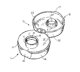
FIG. 1 is a fragmentary perspective view of a closure
and container embodying the invention.
FIG~ 2 is a perspective view of the closure in open
position.
FIG. 3 is a plan view of the closure in open position.
FIG. 4 is a sectional view taken along the line 4-4
in FIG. 3.
FIG. 5 is a sectional view taken along the line 5~5
in FIG. 6.
FIG. 6 is a plan view of theclosurein closedposition.
FIG. 7 is a fragmentary sectional view on an enlarged
scale taken along the line 7-7 in FIG. 3.
FIG. 8 is a fragmentary sectional view on an enlarged
scale taken along the line 8-8 in FIG, 3.
FIG. 9 is a sectional view similar to FIG. 4 showing
the relative positions of the parts in an intermediate position
between open and closed positions.
FIG. 10 is a fragmentary view taken along the line 10-
10 in FIG. 9.
; ;~
:

~2~7~
Descr iption
Referring to FIGS. 1-10, the closure 10 embodying the
invention is made of plastic such as polypropylene and comprises
a first part 11 which is adapted to be threaded on the neck of
a container C and a second part 12 which forms a cap and hinged
to the first part 11.
The first part 11 includes a base wall 14 and a
peripheral skirt 15 with a shoulder 16 at the juncture of the
base wall 14 and skirt 15. A tubular spout 17 extends from the
exterior surface of base wall 14 and terminates in a chamfer
rim 18. An annular bead 19 is formed on the inner surface of
the spout 17. The skirt 15 is formed with an internal thread 20
on the inner surface thereof for engagement with the threads
on the neck of a container C. The spout 17 provides a dispensing
outlet or the contents of a container on which the closure is
applied.
The second or cap part 12 is formed with a base wall
21 and a peripheral skirt 22. Shoulder 16 is adapted to be
engaged by the free edge 23 of the skirt 22. Spaced concentric
walls 24, 25 are provided on the inner surface of the base waIl
21 and are adapted to telescope over the spout 17 and receive
the spout 17 in the annular space~formed between walls 24, 25
when the cap is moved to closed position. The wall 25 is axially
shorter than the wall 24 to permit the swinglng movement of the
cap 12 into position for engagement of the wall 24 with the
spout 17. Chamfer rim 18 guldes the inner wall 24 into the
opening of the spout 17. The inner diameter of the outer wa~11 25
is slightly less than the outer diameter~of the spout 17 near
the rim 18 such that the wall 25 engages and seals against the
outer surface of the spout 170 Bead 19 provides a friction fit
-4-

~3~77~
for innermost wall 24 to both insure a tight seal for the
contents of the container and clean the spout of contents in
the region adjacent rim 18. The friction fit also secures the
second part 12 in closed position.
Peripheral skirt 15 of the first part 11 is formed
with a flattened external surface 26 that underlies a portion
27 on the skirt 22 of the second part 12 so that the portion 27
can be engaged by the thumb or finger of the user to open the
closure. The portion 26 extends circumferentially and blends
into the skirt 15 so that the cap part 12 is less likely to pop
out and interfere with capping or case packing of the closed
container.
A pair of integral flexible hinges 30 extend between
adjacent portions of the first part 11 and second cap part 12
from the area of juncture of the skirts 15, 22 and their
respective base walls 14 and 21~ Hinges 30 flex without any
substantial stress and form the hinge line between the parts
11 and 12. A short relatively rigid strap 31 connects the
skirts 15, 22 between hinges 30 along a radial line. Strap 31
is relatively rigid and is connected to the skirt 15 of part 11
by an integral thinner flexible hinge 32 and to the portion 34
of skirt 22 of part 12 by an integral flexible thinner hinge 33.
Strap 31 is hinged to skirt 15 at a paint spaced
axially from the hinge point of hinges 30 to the skirt 15. Strap
31 is hinged to skirt portion 34 at a point lying on the plane
containing the points of attachment of hinges 30 to the ~kirt
22. As a result when the part 11 is open, as shown in Fig. 7j
and the axes of the parts are parallel, the strap forms an acute
angle A with a plane containing the free edge of skirt 22 and
hinges 30. The radial length of strap 31 i5 less than the radius

132~77~
of the arc through which the second cap part 12 is guided for
movement by the hinges 30 to and from an open and closed position
(Fig. 7). The adjacent wall portion 34 of the cap part 12 is
thinner than the remainder of the skirt 22 such that the strap
31 flexes the wall portion 34 radially outwardly, as shown in
FIGS. 9 and 10, through an angle s (FIG. 9) and the wall portion
34 functions as a sole spring tending to move the cap part 12
to open or close the cap part 12. Strap 31 causes wall portion
34 of cap part 12 to deflect while rotating between open and
closed positions by pulling the skirt against its normal path.
The reaction of the skirt to this pulling action is to tend to
forc~ the second part to remain open, or to tend to close the
second part after sufficient rotation is made in the closing
motion.
Referring more specifically to FIGS. 9 and 10 as the
closure is moved from open to closed position, the strap 31 is
placed under tension and since it has a length less than the
arc through which the parts move, it flexes the ~hin wall portion
34 radially outwardly relative to the part 12 to the position
shown in FIG. 10. At the point of maximum tension in the strap
31, the spring force provided by flexing of the wall portion
3~ provides a stress tending to move the cap part 12 toward the
closed position. When the part is moved toward an open position,
the same condition is reached wherein the wall portion 34 is
flexed in the movement of thecap part12 toward the openposition.

Dessin représentatif
Une figure unique qui représente un dessin illustrant l'invention.
États administratifs

2024-08-01 : Dans le cadre de la transition vers les Brevets de nouvelle génération (BNG), la base de données sur les brevets canadiens (BDBC) contient désormais un Historique d'événement plus détaillé, qui reproduit le Journal des événements de notre nouvelle solution interne.

Veuillez noter que les événements débutant par « Inactive : » se réfèrent à des événements qui ne sont plus utilisés dans notre nouvelle solution interne.

Pour une meilleure compréhension de l'état de la demande ou brevet qui figure sur cette page, la rubrique Mise en garde , et les descriptions de Brevet , Historique d'événement , Taxes périodiques et Historique des paiements devraient être consultées.

Historique d'événement

Description Date
Le délai pour l'annulation est expiré 2002-09-03
Lettre envoyée 2001-08-31
Accordé par délivrance 1993-08-31

Historique d'abandonnement

Il n'y a pas d'historique d'abandonnement

Historique des taxes

Type de taxes Anniversaire Échéance Date payée
TM (catégorie 1, 4e anniv.) - générale 1997-09-02 1997-07-11
TM (catégorie 1, 5e anniv.) - générale 1998-08-31 1998-07-06
TM (catégorie 1, 6e anniv.) - générale 1999-08-31 1999-07-02
TM (catégorie 1, 7e anniv.) - générale 2000-08-31 2000-07-04
Titulaires au dossier

Les titulaires actuels et antérieures au dossier sont affichés en ordre alphabétique.

Titulaires actuels au dossier
OWENS-ILLINOIS CLOSURE INC.
Titulaires antérieures au dossier
WILLIAM E. FILLMORE
Les propriétaires antérieurs qui ne figurent pas dans la liste des « Propriétaires au dossier » apparaîtront dans d'autres documents au dossier.
Documents

Pour visionner les fichiers sélectionnés, entrer le code reCAPTCHA :


Pour visualiser une image, cliquer sur un lien dans la colonne description du document (Temporairement non-disponible). Pour télécharger l'image (les images), cliquer l'une ou plusieurs cases à cocher dans la première colonne et ensuite cliquer sur le bouton "Télécharger sélection en format PDF (archive Zip)" ou le bouton "Télécharger sélection (en un fichier PDF fusionné)".

Liste des documents de brevet publiés et non publiés sur la BDBC .

Si vous avez des difficultés à accéder au contenu, veuillez communiquer avec le Centre de services à la clientèle au 1-866-997-1936, ou envoyer un courriel au Centre de service à la clientèle de l'OPIC.

({010=Tous les documents, 020=Au moment du dépôt, 030=Au moment de la mise à la disponibilité du public, 040=À la délivrance, 050=Examen, 060=Correspondance reçue, 070=Divers, 080=Correspondance envoyée, 090=Paiement})


Description du
Document 
Date
(aaaa-mm-jj) 
Nombre de pages   Taille de l'image (Ko) 
Dessins 1994-03-03 5 102
Revendications 1994-03-03 2 42
Abrégé 1994-03-03 1 38
Description 1994-03-03 6 199
Dessin représentatif 2002-01-03 1 11
Avis concernant la taxe de maintien 2001-09-30 1 179
Taxes 1996-07-14 1 71
Taxes 1995-07-16 1 65
Demande de l'examinateur 1992-01-20 1 54
Correspondance reliée au PCT 1993-05-13 1 29
Correspondance de la poursuite 1992-04-13 3 84