Note : Les descriptions sont présentées dans la langue officielle dans laquelle elles ont été soumises.
1322028
TITLE OF T13E: INVI~NTION
MOI)UL7~TION SYSTE:M FOR E:VOI~ED J~ESPONSE
S'l`lMUL~'l`ION ~\ND M13TIIOD
F I I~Ll) OF '~11 E I NVl~N 'I'I ON
The present invention relates to an evoked response
stimulation system intended for biomedical applications.
More particularly, the present invention relates to a
modulation system ~or evoking a response stimulation and
a method thereof.
.
Bl~CKGROUND OF TllE INVENTION
.._ ..
Electric stimulation and low-power laser devices
principally dominate the field of evoked response stimu-
lation. However, several other devices may be utili,zed
as stimulation sources such as devices using magnetic and
~15 electromagnetic flelds, non-collerent light, acoustic energy
sources, and electrical or mechanical impulses.
rather limited range of modulation schemes have been
used to control the above mentioned deviaes. Pertinent
' ~ refçrences include the following: U.S. Patent No. 3,085,5'66
20~ to Tolles whi h describes a measuring device wherein a pair
of slnsoidal electrical wave forms may be applied either
,"i~ singly or summed together as phasors such that the patient
- ,, . .
2- ~ ~
.
~.
~322028
¦ receives tl-e vector sum o~ both waverorms. U.S. Patent
¦ No. 3,900,020 to Lock describes an electric acupuncture
¦ device W]liC}I employs two oscillators and is arranged so that
l each oscillator can be appliecl to separate needles or probes
¦ such that no CommOIl ground exists between the outputs of
¦ the oscillators. Tl~iS design permits no interaction between
¦ the oscillators. U.S. Patent No. ~,US2,978 to Eugenio describes
an electrotherapy apparatus which employs a single low freguency
oscillator and detection means to locate and treat diseased
¦ organs by the application of electrical currents. U.S. Patent
No. 4,112,923 to Tomocek describes an antonomic transcutaneous
affect device which employs a single oscillator and controls
for timing, intensity, frequency, and waveform polarity. In
l addition, a circuit is provided to locate desired acupuncture
l points. U.S. Patent No. 4,589,417 to Eseifan describes an
l apparatus for selective measuring and treating disordered
¦ tissues which employs a single oscillator in conjunction
with a sensing device to establish and treat specific acu-
puncture points.
¦ In addition the European market has a device which
¦ employs a chain of monostable oscillators to allow independent
¦ ad~ustment of pulse repetition rate, pulse train on tlme,
pulse train off-time, and insertion of intermediate pulses
~ between pulse trains. This device employs a pulse repetition
¦ 25 rate modulator control unit which is separate from the CW
I laser unit and which was originally designed to be used for
_3_
1322028
direct electricaJ s~in~ulatioll wi~l\ tlle laser illteractio
as an ater ~l~ou~JI~ e pulse widtll oE this modulator
¦ is fixed in the desiyll and not un~er operator control. Iaser
l output amplitude is, l~owever, nlallually adjustable.
¦ ~t tlle presellt time, this area oE the aLt includes
¦ biostimulatiol~ lasel-s wl~ich can be divi~ed into: Continuous
¦ Wave (Cw) laser.s (emL~loyin~ tubes or so1id state Cl~ diodes),
¦ Pulse Lasers (em~loying ~ switchillg or solid statc l~ulse diodes).
l In a~itionr eacl~ of the above two categories can be divided
l into species by modulatioll to i~cluc1e: binary scaled pulse
repetitioll rate divi~ers, analoq (musicr noise, or tones)r and
variable on/oEe modulatiorl.
In general, CW lasers are available Wit]l either no
l modulatioll or witl~ variahle rrec)uellcy (e.g., on/oEf)
¦ mo-.lulatioll. ~'ulse diode la.~er~ a~e virtually all oE the
binary scaled ~1ivid(r type (usually employill~ 7 or ~ fixed
divide-by-2 scalin~ options), llowever, there is no clear-
cut line. ~lld, units are availa~le with some of these simple
modulation options and witll in~aepen~aent CW and Pulse laser
sources controlled r~OIll a sirly]e ellclosure.
The purpose o~ nny modlllatiol- ls to vary the stimulation
provide~a to the subject. Stimu:Lation apl~ears to be a
Eunctlon oE the ~ollowing~
a. Tlle modulation or lack thereoE (e.g., a continuous
wave) on tlle incide~lt laser bealll or other stimulation source.
1~ 1
1322028
l b. The wavelength of the laser affects the penetration
¦ depth into the skin surface (as well as underlying tissue) and
¦ may affect different photosensitive electrolyte compounds
¦ differently. It is also suspected that the compressive
¦ acoustic wavelength of ultrasonic sources and the electro~
¦ magnetic wave (e.g., transverse wave, per Maxwells equations)
¦ may have some bearing Oll the overall stimulation of the
patient.
l c. The location o the incident laser beam or other
¦ type oE source on the skin surface.
¦ d. The pattern created in the nervous system when
multiple laser beams and/or other stimulation sources are
used simultaneously Oll the patient.
¦ e. The power level of the energy beam and the duration
¦ that the beam is applied to the subject.
¦ It should be noted that safety ~principally eye safety)
¦ is a major factor in the use of any laser device. An implicit
I I goal in the development of a laser and modulation system used
¦ for biostimulation is to minimize both the peak and the average
¦ beam energy required to effect a given type of stimulation. It
is clear that most of the devices currently on the market have
ignored thiæ factor. ~s a result, many devices exist which
constitu-te a potential eye hazard if improperly employed.
Moreover, a few of the latest devices have sufficient beam
energy where damage to skin cells may be concurrent with
improper use.
,.
I _5_
':
. 1322028
¦ Norl-laser, non-electrical stimulation sources are
¦ principally oL the diatllermy (e.g., higll ~requency
¦ electromaynetic waves) and ultra~out-d (e.~., ultrasonic
¦ acoustic wave types). Whell employed in a pulsed mode both
S ¦ are generallv gate~ at twice ~lle line frequellcy (e.~., 100
¦ }lertz in Europe and 120 llertæ itl North ~merica). Electro-
¦ magnetic sources, while quite rare, generally appear to
employ some form of the aforelllentioned binary scaled modulation.
¦ SU~IMARY OF TIIE: INV13NTION
One aspect of the present invention is a novel and
improved modulation system for generating evoked response
stimulation pulses.
¦ The modulation system comprises, in combination,: a
1 first variable frequency oscillator, a second variable
l frequency oscillator, a ~irst adjustment means, a second
¦ adjustment means, a gatin~ mealls, and a stimulation means.
The first variable frequency oscillator has an output.
¦ The output of the first variable frequency oscillator i9
¦ a first pulsed waveform which has a first pulsed waveform
¦ frequency.
The second variable frequency oscillator has an output.
The output of the second variable Erequency oscillator is
a second pulsed waveforrn which has a second pulsed waveform
frequertcy.
1, ~
I
I -6-
ll 1322028
¦ The first pulsed waveform frequency is greater than
¦ the second pulsed waveform frequency.
¦ The first adjustment means is for adjusting the first
I variable fre(~uency oscillator. The first adjustment
¦ means is operably connected to the first variable frequency
¦ oscillator.
The second adjustment means is for adjusting the second
variable frequency oscillator. The second adjustment means
l i5 operably connected to the second variable frequency
¦ oscillator.
The gatiny means effectuates a logical operator AND.
The gating means has a first input, a second input, and an
output. The first input of the gating means is operably
~ ¦ connected to the output of the first variable frequency
l oscillator. l'he second input oE the gating means is operably
connected to the output of the second variable frequency
oscillator.
The stimulation means evokes a response stimulation from
a person. The stimulation means has an input and an output.
l'he input of the stimulation means being operably connected
to the output of the gating means. The output of the
stlmulation means is the evoked response stimulation pulses.
Another aspect of the present invention is a novel and
improved modulation system for generating evoked response
stimulation pulses.
1 .
1322028
¦ 'l'lle modulati~u 9y51:elll COIIII~J~ c';, ill conl~ atioll: a
¦ first variaL)le fre(luellcy osclllato]-, a secol~d v~riable
¦ frequency oscillator, a first adjustmtallt means, a second
¦ adjustlllent means, a (Jrouncl relerencillq meal~s, a cJatillg means,
¦ a pulse widtll modulatillt3 mealls, alld a stimulation means.
¦ 'l'lle first variable frequellcy oscillator llas an output.
¦ Tlle outL)ut of tlle first variable Eret~uency oscillator is a
¦ first ~ulsed waveforlll wllicll llns a first pulsed waveform
l frequency. 'l'llese pulses are u9ually rectangular.
l 'l'lle second variable fre~luellcy oscillator 'l)as an output.
Tl~e output of tlle secontl variaL)le frequency oscillator is a
second pùlsed waveforlll wllicll llas a second pulsed waveEorm
¦ frequency. 'l'llese ~ulses are nlways rectallgular.
l 'l'lle first pulsctl waveEorm fre~luellcy is greater than tl~e
l second pulsed waveLorm frecluency.
'l'lle first adjusl:ment mean3 is for adjust tlle frist
variable fre(~uency oscillator. 'l'l~e f~,rst adjustment means
is operably conlltacted to tlle first variable fret~uency
oscillator .
Tl~e second adjustmerlt: means is for adjusting the second
variable ~requency oscillator. Tlle second adjustment means
is operal~ly connc!cted to tl~e secolld variable frequency
oscillator.
Tlle grountil reEeL-encillg means llas a safety switching
means and an invertillt3 means. 'l'lle safety switclling means
11
- -
.
`~! 1322028
¦ is operably connected lo the in~erting means and ground.
¦ The gating means eEfectuates a logical operator ~ND.
¦ The gating means has a irst input, a second input, a third
¦ input, and an output. Tl~e ~irst input of the gating means
¦ is operably connected to the output of the first variable
¦ frequency oscillator. ~l~he second input of the gating means
¦ is operably connected to the output of the second variable
¦ frequency oscillator. The third input of the gating means
¦ is operably connected to the inverting means.
¦ The pulse width modulating means for controlling pulse
width has an input and an output. The input of the pulse
width modulating means is operably connected to the output
of the gating means.
. ¦ The stimulation means evokes a response stimulation
¦ from a person. The stimulation means has an input and an
¦ output. The input of the stimulation means is operably
connected to the output of the pulse width modulating means.
¦ Theoutputof the stimulation means is the evoked response
¦ stimulation pulses.
A further aspect oE the present invention is a novel
and improved method of generating evoked response stimulation
pulses.
The method comprises the Eollowing steps:
~ Step 1 - A first adjustment means of a first variable
I ~ frequency oscillator is adjusted to obtain a first pulsed
1;. ~
_g_
1322028
¦ waveform w}lich has a Eirst pulsed waveform frequency.
¦ Step 2 - ~ second adjustlnent means of a second variable
¦ frequency oscillator is adjusted to obtain a secondpulse
¦ waveform wllich l-as a second pulse(l waveform frequency.
¦ Step 3 - Evoked response stimulation pulses are
applied to a person. The evoked response stimulation pulses
¦ are generated Erom an output of a stimulation means. The
stimulation means has an input operably connected to
l an output of a gating means. The gating means effectuates
¦ a logical operator ~ND. The gating means has a first input
and a second input. The first input of the gating means is
l operably connected to an output of a first variable frequency
¦ oscillator. The output of the first variable frequency
l oscillator is the first pulsed waveform from Step 1. The
1~ ¦ second input of the gating means is operably connected to
an output of a second variable frequency oscillator is the
second pulsed waveform from Step 2.
BRIEF DESCRIPTION OF TllE DR~WINGS
, .......................... _
The various objects, advantages, and novel features
will be more fully apparent from a reading of the following
detailed description when read in connection with the
accompanying drawing, in whicll like numerals refer to like
parts, and in which:
; FIG. 1 is a schematic block diagram of diayram of the
~ ~ Fgs. 3-~ s~
~ 25 simplest embodiment of the inventioll. A~ lYu~t-i-s~the
--1 0--
:'-
1322028
I relationship between the inventioll and the plurality of
¦ transducers potentially to be used Wit}l the invention.
¦ FIG. 2 is a schematic block diagram of how this
¦ invention may be setup to al]ow ~or microprocessor control
¦ over each stimulation source and how an external sensor may
be interfaced and used to a]ter control settings in place of
a human operator. In this embodiment signal amplitude as
1 well as pulse repe~ition rate is accomplished within the
¦ physical limits of each transducer.
¦ DET~IL~D DESCRIPTION OF Tll~ PR~FE~RED EMBODIMENTS
I . . . _
¦ This invention deals specifically with a type of modulation
which enhances evoked response stimulation pertaining to
¦ neurological and biophysical applications. Specifically,
l it is a hybrid of low frequency on/off moaulation with an
approximate 50~ duty cycle used to gate higher frequency
pulse trains. This modulation appears more stimulating
than either waveform when separately employed. Both the
on/off rate and the rate of high frequency pulse generation
may be varied. In addition, the pulse width may also be
varied. The ratio of on to oEf is held essentially constant
at a nominal 50~ duty cycle.
Tlle teclllliques dlsclosed in this invention are intended
to minimize the amount of energy and treatment time from any
7': particular energy source employed for experimentation and/or
:. :
-11 -
' 11 '
1 1322~28
¦ treatment in neurological and/or biophysical stimulation
I while permitting maximum e~fectiveness from single or grouped
¦ lasers (or otller energy sources) in achieving a desired
¦ evoked response mechanism.
¦ In addition, a technique is described to allow extension
¦ of this modulation to a group oE lasers by employing a
¦ circuit to ef~ect coordination between their respective
¦ modulations. This approach permits a greater range o~
¦ experimental evoked response strategies to be employed while
¦ minimizing the energy employed in any given laser beam or
other energy source used to evoke stimulation.
I The means used to generate the basic modulation timing
¦ may be simple variable frequency oscillators of common form.
These may also be replaced by sophisticated digitally based
l frequency syntllesizers of the type commonly found in radios.
The important feature appears to be the ability to allow for
l fine (preferably continuous) incremen~ation. The subject
¦ who is being stimulated appears to vary much more than the
l stability of even the crudest variable frequency oscillator.
¦ Control o the system may be manual where the operator
¦ adjusts the oscillators and controls the application time.
¦ More sophisticated implementationsare also possible where
I ¦ an evoked response sensing device is monitored by a
microprocessor based system which alters control settings
and application interval based upon evoked biophysical or
12-
1322028
neurological indicatc)rs. Pulst- wicltll may be sin)ilarly made
variable.
lhe actual wave~engtl~ U5e(l lor stimulation is determined
l by the stimulation source eml~oyecl. Given ~lle current state
l o~ the art, it is assumed tllat:
¦ a. Tl-e wavelengtt~ oE lasers is ~ixed ~y design. ~lthough
it is acknowleclged tllat varial~le wavelengtll lasers exist in
laboratories tllese lasers are ~oo expensive and cumbersome
l to consider Eor this application al: tlle present time.
¦ b. Ultrasonic acoustic devices are generally resonant
at a single requency witll litt]e or no provision to vary
the wavelengtll of tlle acoustic elllission other than changing
the emitter itselE lo one cut for a different Erequency.
c. Diatllermy and low/higll frequency electromagnetic
sources may be desiglled wi.th fairly substantial tuning
ranges.
d. Dixect contact transcul:alleous electrical stimulation
may be desiglle~ witllfairly broaclwavelength tuninc~ rangesr
if so desirecl.
e. ~lectromecllanical devices (e.g., Solenoidal or
similar linear motion transducers) may also operate over a
fairly broad tuning rancJe,if so desired.
It sllould be clear tllat wlli]e tunincJ o ths emitted
wavelengtll is guite possible for many types of stimula-tion
sources, the most basic embodimerlts of this modulation
1' ~
-13-
~ 1!
i322028
technique will not employ this feature owinq to operational
complexity and cost constraints.
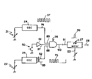
Figures 1 and 2 eacll employ similar numbers to indicate
similar elements. Figure 1 depicts a preferred embodiment
of the present invention. The modulation system for evoked
response stimulation is shown in Pigure 1 comprises gating
means 26, such as a (N)AND gate, for effecting a logical
operator AND. Gating means 26 is used to gate the interaction
of first variable frequency oscillator 24, such as a Signetics
SE566 function generator Witll the inputs from: a) manual
safety and control switcll 50, such as a single pole single
throw momentary contact normally open switch, which is shown
in figure 1 operably connected to inverter 51 which is
operably connected to third input 87 of gating means 26.
Manual safety and control switch 50 main~ains the convention
of using the ground as a reference. b) Second variable
frequency oscillator 25 has an output 52 which has a second
pulsed waveform 38, such as a non-inverted output Q. Second
pulsed waveform 38 has a second pulsed wavefoxm frequency.
~; 20 Output 52 of second variable frequency oscillator 25 isoperably connected to second input 88 of gating mean~ 26.
Second variable frequency oscillator 25 has an on/off duty
cycle. The preferred duty cycle is from about 50 percent
on and 50 percent off. Lesser preferred duty cycle range
-14-
.
~ 1322~28
¦ is from a~out 30 pe~cent on all d 70 percent oEE to about 70
! percellt on all 1 30 percent orE Normal build tolerances
¦ might have a variati.oll of 20 percent in duty cycle. c) First
¦ variable frequency oscillato.r 2~ l~as an output 74 which
¦ has a first pulsed wave.Eorm 37 sucll as a pulse repetition
¦ waveform. Outpùt 74 is operab].y connected to a first input
¦ 89 of a yatiny Illeans 2G. ~irst pul.secl waveform 37 has a
first pulsed waveform Ereque1lcy wllich llas a range of about
¦ 100 times greater tllan -tl~e range oE tlle second pulse
¦ waveform Erequellcy of second pu.Lse waveEorm 3B. The range
¦ of the first pulsed wave~orlll.Ere~luellcy is from about 50
to 2,000 llertz.
Gating means 2G }~as an output 90 operably connected
l to i~lpUt 91 o~ pulse width modulatillg mealls 27, such as a
¦ pulse width Illollostable oscillator, or alternatively output
90 can be operab.ly connectecl directly to input 30 of the
stimulation mean.q. Gating means 26 may also be controlled
in response to an output from all evoked response sensing means
l as received by an interfacing mealls and computed by a
processor means. output 90 of gating means 26 has a composite
waveform 75 whicll is a composil:e oE Eirst pulsed waveform 37
and second pulsed waveform 38. ~s sl~own in ~i~ure i, waveform
75 is furthe.r conditioned by E~ulse width modulating means 27
generating a E.inal. waveEorm 40 at output 28 of pulse width
;
15-
1322~28
21780-330
modulating means 27. Pulse width modulating means 27 has a pulse
width waveform 39. The final width of final waveform 40 is
established either by an operator who varies and controls pulse
width modulating means by employing control input 23, such as a
variable resistor, or, as shown in Figure 2, by an evoked response
sensing means which can vary and control pulse width modulating
means 27.
In a similar manner *irst adjustment means 21, such as a
variable resistor, and second adjustment means 22, such as a vari-
able resistor, are employed by an operator to adjust first vari-
able frequency oscillator 24 and second variable frequency
oscillator 25 respectively, or as shown in Figure 2, a signal
generated in an evoked response sensing means can be used to alter
the first pulsed waveform frequency of first variable frequency
oscillator 24 or the second pulsed waveform frequency of second
variable frequency oscillator 25. First adjustment means 21 is
operably connected to first variable frequency oscillator 24 and
second adjustment means 22 is operably connected to second fre-
quency oscillator 25 as shown in Figure 1.
Final waveform 40 or alternatively composite waveform 75
~establishes the final pulse width received by input 30 of the
stimulation means. The stimulation means comprises stimulation
devices such as: CW laser 29 (Fig. 7), CW or Q-switched laser 83
(Fig. 8), laser 96 (Fig. 9), piezo electric transducer 81
(Fig. 3), electromagnetic field transducer 95 ~Fig. 5), a solenoid
or a vibratory mechanical device 84 (Fig. 4), and electric pulse
stimulator 97 (Fig. 6). CW laser 29 has a laser power supply 31
: ~:
- 16 -
~tS
'
1322~28
21780-330
and a CW laser light emission 36. Cw or Q-switched laser 83 has a
laser power supply 78 without modulation input, a shutter inter-
face 82 for Q-switch or electro optical shutter 93, and a CW or Q-
switched laser light emission 92. Pulse laser 96 has a power
supply 33, an SCR 34 used as a gating device for pulse laser diode
76, pulse laser diode 76, a charge storage capacitor 35, and a
pulse laser light emission 94. Pulse laser 96 relies upon the
series resistance of its associate elements (shown in Figure 1 for
simplicity as SCR 34 used as a gating device for pulse laser diode
76 and charge storage capacitor 35) rather than on the final pulse
width to limit the rate of current flow 73. In an analogous
fashion the electro optical shutter (or Q-switch) 93 would limit
pulse width due to physical properties of these devices. Piezo
electric transducer 81, such as an acoustic wave transducer, has a
power supply 41, and an acoustic wave emission 45. Electromag-
netic field transducer 95 has an antenna or coil 80, a power
supply 42, and a transverse electromagnetic field emission 46.
Linear motion transducer 84 has a power supply 43, a linear
pulsating mechanical member 100, a spring 101 and a pulsating
mechanical emission 47. And electrical pulse stimulator 97 has an
electrical impulse amplifier 77, a power supply 44, a variable
resistor 49 for amplitude control over direct
~`
1322~28
¦ stimulatioll waverorm, an ou~put isolation transformer 79,
¦ and a direct electrical stim~llatioll output 48 such as a
¦ small pulsatiny electrical voltage Vo.
¦ In eacll of the devices represented by the final
5 _ ¦ waveform 40 from output ~8 or alternatively composite
¦ waveform 75 from output 90 received by input 30 of the
¦ stimulation means must be ~esigned to accept control
inputs from ontput 28 or alternatively output 9~. Also,
¦ power supplies must be desiyned to provide the desired
¦ stimulus to the respective stimulation means. The output
of each power supply may be ~, D~, and/or RF as required.
In general, power supplies are old in the art. What is
important is tlle ability for the transducer of the stimulation
. ¦ means and power supply to provide an appropriate interface
¦ at input 30 and transmit appropriate power to the respective
¦ transducer.
¦ There is no theoretical limit to the number of stimulation
¦ means that can be operably connected to the Q or Q-not outputs
l of the second variable frequency oscillator 25 other than the
¦ fanout of output 28 or 90 respectively. In practice the user
¦ would probably be limited by adjustment complexity if the
I ¦ number of stimulation means were greater than four.
. ¦ It should be noted that second variable frequency
I ¦ oscillator 25 has a ~-not output 5~ as shown in Figure 1.
,,' I
, -18-
:
, .
. 11
.
132~028
¦ The waveform 54 of Q-not out~ut 53 is the opposite of
¦ second pulsed waveform 38. Q-not output 53 can be used
¦ to trigger a 5econd ~ND gate of~the same form as gating
_ ¦ means 26, thus allowing for al~ernative blinkillg, off and¦ on, and controlling of two or more stimulation means such ~hat
l while first variable frequency oscillator 24 is gated off
¦ a third variable frequency oscillator, identical in form to
first variable frequency oscillator 24, is gated on.
l Conversely, up to the fanout limit of pulse width
¦ modulating means 27, any number of stimulation sources may
be synchronized off of second variable frequency osciliator 25.
¦ Alternatively, second variable frequency oscillator 25
can be used to drive a counter l-aving counter outputs in
l which only a single counter output is enabled at any instant.
¦ q~he counter outputs are used to sequentially gate a plurality
¦ of additional variable frequency oscillators identical in form
l to first variable frequency oscillator 24. The identical
¦ variable frequency oscillators would each be operably connected
; ¦ to a separate stimulation means such that sequential blinking,
¦ on and off, oE the separate stimulation means is obtained.
¦ In addition, second variable Erequency oscillator 25
¦ can gate first variable frequency oscillator 24 by turning
¦ on and ofE the power supplied to first variable frequency
t~
1 --1 9--
11 ' I
1322028
¦ oscillator 24 or by tUrllillg on al~d off tlle output of
¦ first vari~}~le fl.equency oscillator 24.
e evoked response stimulation pulses can have their
¦ width deterl~ ed Erom tlle Eollowing: a capacitor, an
. I energy discllar~3e circuit means, a transistor gating circuit
¦ means, a power supply vo].tage amplitude means, and a
¦ monostable pulse width lnodulator circuit mealls, or their
¦ widt-h can be del:ermined by al~ electro-optical shutter means
¦ or a Q-switcllinc3 means.
¦ First variable freyuency oscillator 24 and second
variable frequeTlcy osci.l.latol- 25 eall be replaced by frequency
syntllesizers llaving an octave resolution e~ual to or less
than 1/.10.
l ~igure 2 depicts a substalltially more eomplicated
embodiment of tlle present inventioll which utilizes a
micro processor f.6 sucll as a micro comp~ter, to effect control
ancl coordination ~mOrlcJ the nlarly elements.
¦ ` This embodimellt includes botll a stimulation control bus
¦ 56, a micro computer interface bus 57 to eEfect both control
¦ over the other elemellts, and an e~ternal interface port 71
Lo allow the use of external sensor means. The signals
received through external interface port 71 are evaluated by
~ mi.cro p~ocessor 66 and USillg comlllands stored in miero eomputer
.~: memory 72 outputs comlnands througl~ control bus interfaee 65.
,
20-
.
l322028
¦ 'l`l~e user is ;l~terEaced to ~lle system v.ia tlle display/
¦ keyboard unit 67 tlnls providi.ng access to all aforementioned
¦ elements plus peri~eral support cllips 70.
¦ ~rlle elenlellts in ~i~ure 1 llave .been modiEied to allow
¦ automation and ne.~r real .ime control in figure 2. The
¦ modificati.ons are: First var.iable frequency oscillator 24,
¦ shown i.n figure 2, llOW connects -tl~rough stimulatios~ bus
¦ interEace 58. Second variable ~requency oscillator 25,
l shown in figure 2, now COnlleCtS through stimulation bus
1 inter~ace 63, and pulse widtl~ modulatin~ means 27, shown
in figure 2, now conllects throl.l~lh sti.mulation bus interface
85.
~mplitude moclulator (~M) control 64 acting via bus
l interface.68 tllrougll power supp:l.y means 69, such as power
¦ supplies 31, 33, 41, 42, 43, 44, and 78 WhiCIl permits the
¦ amplitude control o~ eacll stimulation means connected to trans-
ducer output to be varied in near real time as determined by
micro processor 66. ~ e stimul~tion control bus 56 supplies
¦ data to amplitude modulator menns 64 using bus inter~ace 62.
~ 20 ¦ Bus interEace 60 interfaces witll extended stimulation control
I ¦ bus 56 and bus inter~ace 65 interfaces with micro computer bus
¦ 57. Tl~e stimulatiorl bus 56 interfaces wi.th variable blink
. ~ I
I
J~ ~ :
~ -21-
11 1
,
` 1322028
¦ delay oscillator 32 at bus interface 59.
¦ ~ven thougll a miclo processor is perEorming the major
control func~ions, manual safety and control switch 50 is
¦ still retained for reasons oE saEety on each gating means 26
¦ shown in figure 2.
l ~ CTION OF OPE~ TING P~RI~MI~TE~S
lhe modulation parameters are bounded by the physical
limitations of the stimulation sources employed. It is also
bounded by associated circuit components. In practice,
however, the modulation required to achieve normal stimulation
is easily within the boundaries of current circuit technology.
The ratio of the maximum blink Erequency to the maximum
pulse repetition rate is about 1 to 100.
sy experimentation it has been found that by adjusting
the pulse repetition rate, a point of maximum sensation can
be found. This adjustment pOillt varies Erom person to person
and also apparently with the health of the area being stlmulated.
Below and above the adjustment for maximum sensation nothing
is felt during short periods oE stimulation. Often, when
a laser is adjusted to the setting for maximum sensation,
the subject often perceives stimulation a substal~tial distance
away from the point Oll the body at which the laser is aim~d~
This sensation is yenerally repea-table from individual to
individual. ~ltl-oug}l, it should be noted that certain
, ~,
-22-
, .
1322028
¦ individuals claim to feel notl~ regardless of laser setting
¦ or duration of exposure.
¦ This maximum point settin~ t a yarticular individual
¦ feels appears, on the average to be constant over a long
¦ period of time. It appears to drop under the following
¦ conditions
¦ a. ~ general illness such as co]d or flu will cause
¦ a measurable drop oE the maximum stimulation ELequency.
l If tlle illness is very severe the Eeeling of stimulation may
¦ be entirely absent.
b. A bruise or other physical injury will produce a
localized drop in the maximum stimulation ~requency. The
frequency will increase as healitlg occurs and the bruise
. ¦ goes away. Concurrelltly, the laseL appears to speed up
¦ the time it takes for bruises to disap~ear. The maximum
¦ stimulation frequency will remain below normal for several
days after the visible effects of an injury have disappeared.
Large scale statistical trials have notbeenundertaken,
. ¦ however; the median maximum stirnulation Erequencies appear
1 to be about 200 pulses per second for men Wit]l women running
up to several times this rate. Based upon the foregoing,
a maximum stimulatioJI frequency oE 2000 pulses per second
was chosen as a practical limit Eor experimentation. ~lthough,
certain equil~mellts have ~een ~uilt with pulse repe~ition
rates up to 399,999 pulses yer second.
.~ .
-23-
1322028
¦ ~elow and above the setting for maximum stimulation
¦ some local stimulation can oftel~ be felt aELer very long
periods compared to those required at the setting ~or maximum
l stimulation. These other settings are not without experi-
¦ mental interest. Ilowever, ~airly sophisticatea evoked
response sensing equipment is required to analyze the
results achieved from the use of these settings.
In the course of experimenting with different pulse
l repetition rates it became apparent that some mechanis~n was
¦ desirable to speed up the evoked response stimulation
¦ process. The prevailing European approach has been to go to
higher and highel power levels with general disregar~ for
the safety implications this raises. European literature
does not generally draw a distinct line between a laser
for evoked response stimulation and using it for concurrent
tissue heating.
The incorporation of a dual modulation technique was
tried to speed up the achievement of an evoked response while
minimizing the average power level required to achieve a
desired respon~e. This dual modulation consists oE the
above descri~ed pulse repetition rate ad~ustment approach
coupled with a secondary modulation rate that gates the
primary (and higher) modulation rate on and off. For
` convenience this i9 referred to as "blinking".
-24-
~322028
The blink ~re~uency ranye was chosen by experimentation.
Within the upper pulse repetition ra~e bound chosen at 2000
pps, a blink rate oE 8-lO hertz appears to enllance the effective-
l ness of the basic pulsed waveform. This correlates nicely
¦ with the electrical stimulation theory develoued by Vollover the last 40 vears or so. Wllile more sophisticated
evoked response monitors may extend this range, an up~er
bound of 20 hertz was clloserl based upon the limits of
l utility perceivable without sophisticated instrumentation.
¦ The 50% duty cycle was also chosell by similar experimentation.
While these values appear very effe~tive, further
refinement may be possible witll more sophisticated
¦ instrumentation thall is currently available. As such. the
upper and lower boundaries for both the pulse repetition
¦ rate and the blink rate may shift somewhat as may the
¦ blink duty cycle limits.
¦ It is possible to extend the basic modulatiorl concept
to incor~orate stimulation energy patterns generated on
l different parts of ~he subject ~hroughthe coordinated use
~¦ ~f multiple energy sources.
¦ The choice of the patterns to be generated by a system
of this kind is based upon tl~e perceived need to stimulate
¦ muItiple points in precisely deEined ways in order to evo~e
¦ different neurological/biopllysical responses and~or to
I ~ ¦ enhance the response achieved by stimulating a single point.
-~S-
~: I
,
,
1322028
¦ While tllere llas been shown ancl described what is at
¦ present consiclered the prefe.rrecl embocliment oE the invention,
¦ it wili be obvious to those skilled in the art that various
l changes and modifications may be made therein without
S ¦ department from the scope of the invention.
:. .
' ~ -26-