Sélection de la langue

Search

Sommaire du brevet 1322651 

Énoncé de désistement de responsabilité concernant l'information provenant de tiers

Une partie des informations de ce site Web a été fournie par des sources externes. Le gouvernement du Canada n'assume aucune responsabilité concernant la précision, l'actualité ou la fiabilité des informations fournies par les sources externes. Les utilisateurs qui désirent employer cette information devraient consulter directement la source des informations. Le contenu fourni par les sources externes n'est pas assujetti aux exigences sur les langues officielles, la protection des renseignements personnels et l'accessibilité.

Disponibilité de l'Abrégé et des Revendications

L'apparition de différences dans le texte et l'image des Revendications et de l'Abrégé dépend du moment auquel le document est publié. Les textes des Revendications et de l'Abrégé sont affichés :

  • lorsque la demande peut être examinée par le public;
  • lorsque le brevet est émis (délivrance).
(12) Brevet: (11) CA 1322651
(21) Numéro de la demande: 1322651
(54) Titre français: RASOIR ELECTRIQUE
(54) Titre anglais: ELECTRIC SHAVING APPARATUS
Statut: Périmé et au-delà du délai pour l’annulation
Données bibliographiques
(51) Classification internationale des brevets (CIB):
  • B26B 19/28 (2006.01)
  • B26B 19/14 (2006.01)
  • B26B 19/38 (2006.01)
(72) Inventeurs :
  • LABRIJN, HANS
(73) Titulaires :
  • PHILIPS ELECTRONICS N.V.
(71) Demandeurs :
  • PHILIPS ELECTRONICS N.V.
(74) Agent: SMART & BIGGAR LP
(74) Co-agent:
(45) Délivré: 1993-10-05
(22) Date de dépôt: 1988-11-21
Licence disponible: S.O.
Cédé au domaine public: S.O.
(25) Langue des documents déposés: Anglais

Traité de coopération en matière de brevets (PCT): Non

(30) Données de priorité de la demande:
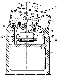
Numéro de la demande Pays / territoire Date
8702812 (Pays-Bas (Royaume des)) 1987-11-24

Abrégés

Abrégé anglais


ABSTRACT:
Electric shaving apparatus.
The invention relates to a shaving apparatus
comprising a housing which can be used as a grip and a
shaving head comprising at least one shaving unit, the
shaving unit being inclined relative to the housing, which
shaving unit comprises a stationary shaving member with hair-
entry apertures and a rotatable shaving member, the rotatable
shaving member being coupled to an electric motor by means of
a drive spindle comprising two portions which are pivotable
relative to one another, i.e. a first drive-spindle portion
coupled to the rotatable shaving member and a second drive-
spindle portion coupled to the motor. The housing is provided
with a bearing by means of which the first drive-spindle
portion is held in an inclined position relative to the
second drive-spindle portion.
Figure 4.

Revendications

Note : Les revendications sont présentées dans la langue officielle dans laquelle elles ont été soumises.


THE EMBODIMENTS OF THE INVENTION IN WHICH AN EXCLUSIVE PROPERTY
OR PRIVILEGE IS CLAIMED ARE DEFINED AS FOLLOWS:
1. A shaving apparatus comprising a housing which
functions as a grip and a shaving head comprising at least
one shaving unit, the shaving unit being in an inclined
position relative to the housing, which shaving unit
comprises a stationary shaving member with hair-entry
apertures and a rotatable shaving member, the rotatable
shaving member being coupled to an electric motor by means of
a drive spindle comprising two portions which are pivotable
relative to one another, including a first drive-spindle
portion coupled to the rotatable shaving member and a second
drive-spindle portion coupled to the motor, characterized in
that the housing is provided with a bearing by means of which
the first drive-spindle portion is maintained in a position
in which the direction of the axis of rotation of said
portion deviates from the direction of the axis of rotation
of the second portion.
2. A shaving apparatus as claimed in Claim 1,
characterized in that the bearing forms part of an at least
partly flexible sealing element arranged between the housing
and the shaving head.
3. A shaving apparatus as claimed in Claim 2,
characterized in that both the motor and the second drive-
spindle portion are carried by a frame which can be mounted
in the housing and which also retains the sealing element.

Description

Note : Les descriptions sont présentées dans la langue officielle dans laquelle elles ont été soumises.


~2~
Electric shaving apparatus.
The invention relates to a shaving apparatus
comprising a housing which functions as a grip and a shaving
head comprising at least one shaving unit, the shaving unit
being in an inclined position relative to the housing, which
shaving unit comprises a stationary shaving member with hair-
entry apertures and a rotatable shaving member~ the rotatable
shaving member being coupled to an electric motor by means of
a drive spindle comprising two portions which are pivotable
relative to one another, including a first drive-spindle
lO portion coupled to the rotatable shaving member and a second
drive-spindle portion coupled to the motor.
Such a shaving apparatus is known, for example, from
United States Patent Specification 4,257,161 (PHN 8940). It
is desirable that during use of the apparatus the shaving
15 head or at least the shaving unit is in an inclined position
relative to the part of the housing which serves as a grip,
so that the shaving unit can be brought in contact with the
- skin to be shaved without strenuous wrist action. In the
known construction, where the axis of rotation of the motor
20 and the axis of rotation of the rotary shaving member have
the same direction, this means that the motor must be
arranged in the shaving head, so that the shaving head
becomes bulky and the weight distribution of the shaver
becomes unfavourable.
It is the object of the invention to mitigate these
drawbacks. To this end it is characterized in that the
housing is provided with a bearing by means of which the
first drive-spindle portion is maintained in a position in
which the direction of the axis of rotation of said portion
30 deviates from the direction of the axis of rotation of the
second portion.
Special embodiments are defined in the appended
.
:, . : , :
: ~ '

1 3 6~ t~
subsidiary Claims.
Embodiments of the invention will now be described
in more detail, by way of example, with reference to the
Figures.
5Figure 1 is a front view of a shaving apparatus in
accordance with the invention.
Figure 2 is a side view of the shaving apparatus
shown in Figure 1.
Figure 3 is a sectional view taken on the line III-
III in Figure 2.
Figure 4 is a sectional view taken on the line IV-IV
in Figure 1.
Figure 5 shows a modification of the embodiment
shown in Figures 1 to 4.
15The shaving apparatus shown in Figures 1 to 4
comprises a housing 1 which functions as a grip, and a
shaving head 2, the shaving head being inclined relative to
the housing, so that the housing and the shaving head adjoin
one another as a vee. The shaving head 2 comprises two
20 shaving units 3, each comprising a stationary shaving member
4 with hair-entry apertures 5 and a rotatable shaving member
6.
The inclined position of a shaving unit 3 relative
to the housing 1 can be defined by the angle between the
25 axis of rotation 7 of a rotatable shaving member 6 and the
longitudinal axis 8 of the housing (Figure 2). Even a
comparatively small value of ~, for example ~= 10, provides
a considerable improvement in shaving convenience.
The rotatable shaving members 6 are coupled to an
30 electromotor 10 by means of drive spindles 9. A drive spindle
9 of a construction known per se comprises a first drive-
spindle portion 11 coupled to the rotatable shaving member 6
and a second drive-spindle portion 12 coupled to the motor
10. For this purpose the second drive-spindle portion 12 is
35 provided with a toothed ring 13 which is in mesh with the
central toothed wheel 14 on the motor shaft 15. A compression
spring 16 arranged between the drive-shaft portions 11 and 12
. .
. ~

~ 3~2~
provides the required pressure between the rotatable shaving
members 6 and the stationary shaving nember 4.
The first drive-spindle portion 11 has a flange 17
which engages in the space 18 in the second drive-spindle
portion 12 to transmit the rotation of the drive-spindle
portion 12 to the drive-spindle portion 11. The drive-spindle
portion 11 can telescope relative to the drive-spindle
portion 12 against the action of the spring 16 and is also
pivotable to a limited extent relative to the drive-spindle
lO portion 12.
The housing 1 is provided with a bearing 19 for the
first drive-spindle portion 11 to hold the first drive-
spindle portion permanently in a tilted position relative to
the second drive-spindle portion 12. This tilted position is
15 such that the axis of rotation 20 of this drive spindle
portion 11 (Figure 4), which axis coincides substantially
with the axis of rotation 7 of the rotatable shaving member
6, is oriented at the desired angle ~ relative to the axis of
rotation 21 of the second drive spindle portion 12, which
20 substantially coincides with the longitudinal axis 8 of the
housing 1.
Preferably, the bearing 19 is constructed as a part
of an at least partly flexible sealing element 22. This
sealing element comprises an annular rubber cup 23, which
25 surrounds the bearing 19, and a circumferential sealing lip
24. This lip engages a groove 25 in the inclined end wall 26
of the housing 1.
The sealing lip 24 is retained by means of an
annular member 27 which forms part of a frame 28 which also
30 carries the motor 10. To this end the frame 28 comprises
hoolcs 29 which engage underneath the motor 10. The frame
comprises a frame plate 30 carrying the journals 31 for the
second drive-spindle portions 12, so that these second drive-
spindle portions are also mounted on the frame. This greatly
35 simplifies mounting of the motor 10 and the drive spindles 9,
whilst at the same time the sealing element 22 is retained.
The sealing lip 24 mainly provides sealing relative to the
.: , :
'. ' ; :.

:~ 3 ,~ ~ v v :~
upright walls 32 and 33 of the groove 25.
For driving the shaving units 3, which are inclined
relative to the housing, the above construction utilizes the
possibilities offered by the existing pivotal drive spindles
9. As a result of this special additional parts such as
flexible shafts or bevel-gear transmissions are not needed.
The motor 10 can be accommodated in the housing 1, so that
the centre of gravity is situated in the housing and the
apparatus is convenient to handle. The shaving head 2
10 comprises only the shaving units 3 and parts of the drive
spindles 9, which provides more freedom with respect to the
design of the shaving head.
Alternatively, the bearing 19 can be mounted
directly in the housing wall 26 of the housing. However, the
5 use of the sealing element 22 results in an apparatus which
may be cleaned with water. The sealing of the drive-spindle
portions 11 can be further improved by providing the rubber
cup 23 with a lip 3~ adjoining the drive-spindle portion 11.
It is obvious that the invention may also be applied
20 to a dry-shaving apparatus as shown in Figure 5 without a
shaving head which adjoins the housing in accordance with a
vee, but in which the shaving unit 3 is merely inclined
relative to said housing 1.
-

Dessin représentatif
Une figure unique qui représente un dessin illustrant l'invention.
États administratifs

2024-08-01 : Dans le cadre de la transition vers les Brevets de nouvelle génération (BNG), la base de données sur les brevets canadiens (BDBC) contient désormais un Historique d'événement plus détaillé, qui reproduit le Journal des événements de notre nouvelle solution interne.

Veuillez noter que les événements débutant par « Inactive : » se réfèrent à des événements qui ne sont plus utilisés dans notre nouvelle solution interne.

Pour une meilleure compréhension de l'état de la demande ou brevet qui figure sur cette page, la rubrique Mise en garde , et les descriptions de Brevet , Historique d'événement , Taxes périodiques et Historique des paiements devraient être consultées.

Historique d'événement

Description Date
Inactive : CIB de MCD 2006-03-11
Le délai pour l'annulation est expiré 1997-10-06
Lettre envoyée 1996-10-07
Accordé par délivrance 1993-10-05

Historique d'abandonnement

Il n'y a pas d'historique d'abandonnement

Titulaires au dossier

Les titulaires actuels et antérieures au dossier sont affichés en ordre alphabétique.

Titulaires actuels au dossier
PHILIPS ELECTRONICS N.V.
Titulaires antérieures au dossier
HANS LABRIJN
Les propriétaires antérieurs qui ne figurent pas dans la liste des « Propriétaires au dossier » apparaîtront dans d'autres documents au dossier.
Documents

Pour visionner les fichiers sélectionnés, entrer le code reCAPTCHA :


Pour visualiser une image, cliquer sur un lien dans la colonne description du document. Pour télécharger l'image (les images), cliquer l'une ou plusieurs cases à cocher dans la première colonne et ensuite cliquer sur le bouton "Télécharger sélection en format PDF (archive Zip)" ou le bouton "Télécharger sélection (en un fichier PDF fusionné)".

Liste des documents de brevet publiés et non publiés sur la BDBC .

Si vous avez des difficultés à accéder au contenu, veuillez communiquer avec le Centre de services à la clientèle au 1-866-997-1936, ou envoyer un courriel au Centre de service à la clientèle de l'OPIC.


Description du
Document 
Date
(aaaa-mm-jj) 
Nombre de pages   Taille de l'image (Ko) 
Revendications 1994-03-03 1 33
Abrégé 1994-03-03 1 22
Dessins 1994-03-03 2 51
Description 1994-03-03 4 146
Dessin représentatif 2001-07-29 1 13
Correspondance reliée au PCT 1993-07-07 1 18
Correspondance de la poursuite 1991-08-01 1 24
Demande de l'examinateur 1991-04-10 1 33
Taxes 1995-09-21 1 76