Sélection de la langue

Search

Sommaire du brevet 1322841 

Énoncé de désistement de responsabilité concernant l'information provenant de tiers

Une partie des informations de ce site Web a été fournie par des sources externes. Le gouvernement du Canada n'assume aucune responsabilité concernant la précision, l'actualité ou la fiabilité des informations fournies par les sources externes. Les utilisateurs qui désirent employer cette information devraient consulter directement la source des informations. Le contenu fourni par les sources externes n'est pas assujetti aux exigences sur les langues officielles, la protection des renseignements personnels et l'accessibilité.

Disponibilité de l'Abrégé et des Revendications

L'apparition de différences dans le texte et l'image des Revendications et de l'Abrégé dépend du moment auquel le document est publié. Les textes des Revendications et de l'Abrégé sont affichés :

  • lorsque la demande peut être examinée par le public;
  • lorsque le brevet est émis (délivrance).
(12) Brevet: (11) CA 1322841
(21) Numéro de la demande: 1322841
(54) Titre français: MACHINE SERVANT A LA POSE DE COMPOSANTS ELECTRONIQUES
(54) Titre anglais: ELECTRONIC COMPONENT INSERTION MACHINE
Statut: Périmé et au-delà du délai pour l’annulation
Données bibliographiques
(51) Classification internationale des brevets (CIB):
  • H05K 3/30 (2006.01)
  • H05K 13/04 (2006.01)
(72) Inventeurs :
  • SOOY, ROBERT J. (Etats-Unis d'Amérique)
  • JACKSON, RODNEY P. (Etats-Unis d'Amérique)
(73) Titulaires :
  • EMHART INDUSTRIES, INC.
  • DYNAPERT, INC.
(71) Demandeurs :
  • EMHART INDUSTRIES, INC. (Etats-Unis d'Amérique)
  • DYNAPERT, INC. (Etats-Unis d'Amérique)
(74) Agent: SWABEY OGILVY RENAULT
(74) Co-agent:
(45) Délivré: 1993-10-12
(22) Date de dépôt: 1989-02-21
Licence disponible: S.O.
Cédé au domaine public: S.O.
(25) Langue des documents déposés: Anglais

Traité de coopération en matière de brevets (PCT): Non

(30) Données de priorité de la demande:
Numéro de la demande Pays / territoire Date
172,620 (Etats-Unis d'Amérique) 1988-03-24

Abrégés

Abrégé anglais


ABSTRACT
ELECTRONIC COMPONENT INSERTION MACHINE
A machine for inserting DIP components. A
DIP component slides down a chute and onto a
mandrel. A thruster advances to thrust the
component against a stop which is secured to the
mandrel. The precisely located component is gripped
and the mandrel is retracted, whereupon component
insertion takes place.

Revendications

Note : Les revendications sont présentées dans la langue officielle dans laquelle elles ont été soumises.


- 4 -
The embodiments of the invention in which an exclu-
sive property or privilege is claimed are defined as
follows:
1. A machine for inserting DIP electronic
components comprising:
chute means, including a chute having a
surface, for receiving a vertically oriented DIP
component and for changing the vertical orientation
of the received component to a substantially
horizontal orientation;
mandrel means including:
an elongated transfer mandrel having a
component receiving surface at the forward end
thereof,
means for supporting said mandrel for
displacement from a retracted position whereat the
front end of said mandrel is spaced from said chute
surface to an advanced position whereat said
component receiving surface of said mandrel is
continuous with said chute surface, whereby a DIP
component dropped onto said chute surface, when said
mandrel is at said advanced position, will slide
down said chute surface onto said mandrel surface,
means for displacing said mandrel from
said retracted position to said advanced position;
stop means securely fastened to said
mandrel a selected distance from said front end;
and,
said chute means further including
thruster means for pushing a component which has
slid down said chute onto said advanced mandrel
against said stop.
2. An inserting machine according to claim 1,
wherein said mandrel means further comprises a
cross-bar secured to said mandrel and wherein said
chute means further comprises a bumper for
cushioning the impact of said cross-bar when said
mandrel is advanced to said advanced position.

- 5 -
3. An inserting machine according to claim 2,
wherein the front of said mandrel is rounded and
wherein said chute has an arcuate cut-out for
receiving said rounded front of the mandrel.

Description

Note : Les descriptions sont présentées dans la langue officielle dans laquelle elles ont été soumises.

322841
ELECTRONIC COMPONENT INSEKTION MACHINE
SPECIFICATION
~ dual in-line package (DIP) componen-t
insertion machine inserts DIP components that may
have up to twenty one (21) leads per side. In
state-of-the-art machines such as disclosed in U.S.
Patent No. 3,550,238, each componen-t is removed from
a magazine and is delivered to a conditioning unit
which forms or straightens the leads. The
conditioned component is released to an arcuate chute
which receives the component in a vertical
orientation and re-orien-ts -the component to a sub-
stantially horizontal orientation before it is
discharged from the chute onto a horizontal transfer
mandrel. The momentum of -the falling component
carries the component forwardly along the mandrel to
a selected location whereat the component is brought
to a halt by a stop mechanism. The transfer mandrel
then advances to a ready position. A spring biased
pusher which is secured to the transfer mandrel
pushes the component past the first stop positively
locating the component against a final positioning
stop mechanism. The component is then gripped by a
finger mechanism, the transfer mandrel and separate
s-top mechanisms are retrac-ted and the finger
mechanism is lowered inserting the gripped component
into a circuit board.
It is an object of the present invention to
improve the component delivery mechanism for an
electronic component insertion machine.
In accordance with a particular embodiment
of the invention there is provided a means for a
machine for inserting DIP electronic components
comprising:
- ~ . ' - '.
.
- ' ' '

- la - 13228~11
chute means, including a chute having a :
sur~ace, for receiving a vertically orien-ted DIP
~; componerlt and for changing the vertical orientation
of the received component to a substantially
~:~ 5 horizontal orienta-tion; :
mandrel means including:
an elongated transfer mandrel having a
~: component receiving surface at the forward end
~: thereof,
~;~ 10 means for supporting said mandrel for
; displacemen-t from a retracted position whereat the
front end of said mandrel is spaced from said chute
. surface to an advanced position whereat said
component receiving ~urEace of said mandrel is
continuous with said chute surface, whereby a DIP
component dropped onto said chute surface, when said
.~ mandrel is at said advanced position, will slide down
.~ said chute surface onto said mandrel surface,
means for displacing said mandrel from said
~: 20 retracted position to said advanced position; :
: stop means securely fastened to said
mandrel a seIected distance from said front end; and, ~.
~ ~ said chute means further including thruster
; means for pushing a component which has slid down
: 25 said chute onto said advanced mandrel against said
stop.
other objects and advantages of the present
: invention will become apparent from the following i
`~ portion of the specification and from the following
~ .
~' , .
., . . , . . , ~ , , ., ~ . . . , :
, . ;, . .,, , , , . ....
' ' : : ' . ; . ... , :
' '- ' . '', ' ': . '
,

- ~3228~
2 --
drawing~ which illu~trate in accordance with the
mandate of the patent statute~ a pre6ently preferred
embodiment incorporating the principles of the
invention.
Referrin~ to the drawings:
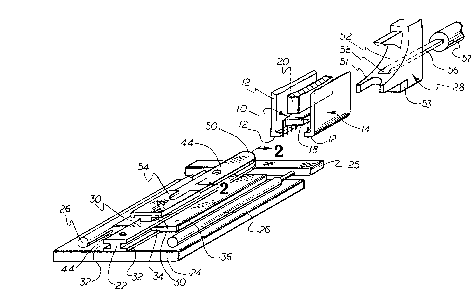
Figure 1 is an obllque view of a portion of a
DIP component ~nsertion machine; and
Figure ~ is a view taken at ~-2 of Figure 1.
The component in6ertion machine will
6equenti~11y locate components 10 (DXP~ or socket~)
at the 111u~trated cendy po~itlon where the oppo~ed
jaws 12 of a gripper mechanism 14 will forcefully
grip the opposed parallel leads of the DIP
component. The body 18 of the DIP component will
underlie the pusher element 20 of the gripper
mechanis~n at the ready position. The gripper
mechanism will be lowered, inserting the leads into
holes in a receiving circuit board ~not shown)
whereupon the jaw6 will be retracted and the pusher
will oe further low~red to fully 6eat the component.
To locate the component 10 at the ready
position, an elongated mandrel 22, which is
~lideably displaceable on a ba~e 24 portion of the
machine frame, and which is secured to a cross bar
25, is advanced by a pair of cylinders 26, or the
like, from the illustrated retracted position to an
advanced position where it enqages the chute
mechanism 28. The mandrel 22 has opposed upper 30
and lower 32 grooves defined in its ~ide walls. The
lower grooves 32 receive the tongue portion 34 of
opposed guides 36, which are secured to the ba~e,
and the upper groove~ 30 receive the innermost end
portions of the opposed jaws 12, which extend
inwardly beyond the lead of a gripped component~ A~
35 can be 6een from Figure 2, a pair of Hall Effect
Sensors 40 are located in the ba~e 24 below the
~andrel and ~ense the pre~ence of magnets 42 secured
within through-bore~ 44 defined in the mandrel. The

~22~
-- 3 --
mandrel can thereby be di~placed between well-
defined advanced and retracted posltion~. The
forward end of the mandrel has a rounded projecting
portion 50 whlch substantially mates with an arcuate
cut-out 51 in the lower portion of the slide surface
52 o~ the chute mechanism 28 when the mandrel is
advanced. A rubber bumper 53 is provided to cushion
the impact of the advancing cross bar 25. When the
mandrel i5 at the advanced position, the slide
surface 52 and the top surface of the mandrel 22
form a continuous surface. A component dropped onto
the chute will slide down the chute surface, which
changes the orientation of the component from
vertical t~ substantially horizontal, onto the
mandrel. The component slides under the pusher 20,
which prevents the component from ~umping off the
mandrel and towards a stop 54 which is ~ecured to
the top of the mandrel ~the mandrel is at the
advanced position). The component is precisely
located against the stop 54 by advancing a spring
biased thruster element 56 which is advanceable by a
cylinder 5~ from a retracted position where its
forward end is located within a suitable hole 58 in
the chute to an advanced position thrusting the
component against the stop.
When the component is precisely located on
the advanced mandrel, the gripping mechanism can be
operated to grip the component. Once the component
is yripped, the mandrel will be retracted ~o that
the gripping mechanism can be partially lowered
inserting the component into the circuit board. The
fingers will then retract releasing the oomponent
and the pusher will engage and fully seat the
component. A cut-clinch mechanism below the circuit
board can then ~ecure the component in place.
.
,, , ' ,
,
.

Dessin représentatif
Une figure unique qui représente un dessin illustrant l'invention.
États administratifs

2024-08-01 : Dans le cadre de la transition vers les Brevets de nouvelle génération (BNG), la base de données sur les brevets canadiens (BDBC) contient désormais un Historique d'événement plus détaillé, qui reproduit le Journal des événements de notre nouvelle solution interne.

Veuillez noter que les événements débutant par « Inactive : » se réfèrent à des événements qui ne sont plus utilisés dans notre nouvelle solution interne.

Pour une meilleure compréhension de l'état de la demande ou brevet qui figure sur cette page, la rubrique Mise en garde , et les descriptions de Brevet , Historique d'événement , Taxes périodiques et Historique des paiements devraient être consultées.

Historique d'événement

Description Date
Inactive : CIB de MCD 2006-03-11
Inactive : Demande ad hoc documentée 1996-10-12
Le délai pour l'annulation est expiré 1996-04-14
Lettre envoyée 1995-10-12
Accordé par délivrance 1993-10-12

Historique d'abandonnement

Il n'y a pas d'historique d'abandonnement

Titulaires au dossier

Les titulaires actuels et antérieures au dossier sont affichés en ordre alphabétique.

Titulaires actuels au dossier
EMHART INDUSTRIES, INC.
DYNAPERT, INC.
Titulaires antérieures au dossier
ROBERT J. SOOY
RODNEY P. JACKSON
Les propriétaires antérieurs qui ne figurent pas dans la liste des « Propriétaires au dossier » apparaîtront dans d'autres documents au dossier.
Documents

Pour visionner les fichiers sélectionnés, entrer le code reCAPTCHA :


Pour visualiser une image, cliquer sur un lien dans la colonne description du document. Pour télécharger l'image (les images), cliquer l'une ou plusieurs cases à cocher dans la première colonne et ensuite cliquer sur le bouton "Télécharger sélection en format PDF (archive Zip)" ou le bouton "Télécharger sélection (en un fichier PDF fusionné)".

Liste des documents de brevet publiés et non publiés sur la BDBC .

Si vous avez des difficultés à accéder au contenu, veuillez communiquer avec le Centre de services à la clientèle au 1-866-997-1936, ou envoyer un courriel au Centre de service à la clientèle de l'OPIC.


Description du
Document 
Date
(aaaa-mm-jj) 
Nombre de pages   Taille de l'image (Ko) 
Page couverture 1994-03-04 1 15
Revendications 1994-03-04 2 44
Dessins 1994-03-04 1 39
Abrégé 1994-03-04 1 10
Description 1994-03-04 4 162
Dessin représentatif 2001-11-26 1 20
Demande de l'examinateur 1992-03-02 1 52
Correspondance reliée au PCT 1993-07-08 1 33
Correspondance de la poursuite 1992-04-08 3 90