Note : Les descriptions sont présentées dans la langue officielle dans laquelle elles ont été soumises.
1 322993
DEVICE FOR ATTACHING WORKING MACHINE TO VEHICLE
BACKGROUND OF THE INVENTION
The present invention relates to a device for
selectively attaching a working machine such as a rotary
cultivator and a backhoe to a vehicle body.
In a vehicle having wheels and and engine such as a
tractor, there are provided at its rear end portion a three
point linking mechanism and a hydraulic device for operating
the linking mechanism. As disclosed in U. S. Patents
4,512,413 and 3,904,051, known are a rotary cultivator or a
backhoe attached to a rear portion of the three points
linking mechanism.
The three points linking mechanism is available for
vertically movably providing an agricultural equipment such
as the rotary cultivator. The mechanism is primarily used
for mounting a working machine having a light weight, and
the mechanism is not frequently used for mounting a heavy
working machine such as the backhoe, since it would be
difficult to provide high strength in the linking mechanism
in order to attach the heavy device.
Therefore, the backhoe is not attached by means of the
three points linking mechanism but is attached directly to
the vehicle body through an attaching portion of the backhoe
as disclosed in Japanese Utility Model Application Kokai
~ 1 3229~3
No.63-161958.
In case of the direct attachment of the backhoe to the
vehicle body, a speicial vehicle body which is exclusively
used for the attachment. of the backhoe must be provided for
the detachably providing the backhoe to such vehicle body.
The special vehicle body is not provided with a connecting
portion of the three points linking mechanism, and
therefore, the vehicle body does not permit the other type
of the agricultural equipment to be attached thereto.
Accordingly, such vehicle body is not available for wide
applicability.
SUMMARY OF THE INVENTION
The present invention has been provided in order to
overcome the above described drawback attendant to the
conventional arrangement.
It is an important object of this invention is to
provide a device for attaching a working machine to a
vehicle in which a heavy weight working machine can be
detachably and fixedly attached to the vehicle and a three
point link working machine can also be attached through a
three points linking mechanism when the heavy workin machine
is not attached to the vehicle. Such advantages are
attained by providing an attachment frame at a rear portion
of the vehicle body, and a working machine connecting
portion for attaching the heavy weight working machine and a
-- 2
1 3229q3
three point link connecting portion for connecting the three
point linking mechanism are juxtaposedly provded at the
attachment frame.
Another important object of the present invention is to
provide such device in which there are provided an upper
and lower connecting portion mounted on the attachment frame
for connecting the rear working machine, a top link
connecting portion and a lower link connecting portion for
connecting the three points linking mechanism, and in which
the top link connecting portion and the lower link
connection portion do not become obstacles when connecting
the rear working machine to the upper and lower connecting
portion, and the the upper and lower connecting portion does
not become an obstacle when connecting the three points
linking mechanism to the top link connecting portion and the
lower link connecting portion.
Still another important object of the invention is to
provide the device for attaching the working machine to the
vehicle in which a reinforcing frame is mountd on the
vehicle for supporting a front working machine to a front
portion, and a rear portion of the reinforcing frame and the
attachment frame are connected together for a mutual
reinforcement.
Still another important object of the invention is to
provide such device in which the connecting portion of the
t 322q93
attachment frama and the a portion to be connected provided
on a mounting frame of the rear working machine is lockable
with each other by locking means, and the rear working
machine can be secured without looseness.
Still another object of the invention is to provide such
device in which a wedge member is used as the locking means
which provides locking connection between the connecting
portion and a portion to be connected, and the wedge member
can be biased by a spring toward an insertion direction, so
that fixed connection without looseness is attainable.
Still another object of the invention is to provide such
device in which locking and releasing operations can be
facilitated by fasilitating insertion of the wedge member of
the locking means and by holding the same at a retracted
position.
These and other objects of the present invention will be
attained by providing a device for attaching a working
machine to a vehicle comprising: a vehicle body having
wheels and an engine: an operator's seat and a maniuplation
handle disposed on the vehicle body; a hydraulic device
mounted on a rear upper portion of the vehicle body for
vertically moving a three point link type working machine; a
rear attachment frame fixedly secured to the rear portion of
the vehicle body; a rear working machine disposed at rear
side of the vehicle and selectively arranged relative to a
1 3~9!?3
three point link type working machine: the attachment frame
being provided with a top link connecting portion adapted to
be connected to a top link for connecting the working
machine, a right and left lower link connecting portion
adapted to be connected to a right and left lower link, an
upper connecting portion adapted to be connected to an upper
coupling portion provided at the front portion of the rear
working machine, and a lower connecting portion adapted to
be connected to a lower coupling portion; an upper locking
means adapted to connect the upper coupling portion to the
upper connecting portion; and a lower locking means adapted
to connect the lower coupling portion to the lower
connecting portion.
In another aspect, the present invention also provides a
device for attaching a working machine to a vehcle
comprising; a vehicle body having wheels and an engine; an
operator's seat and a maniuplation handle disposed on the
vehicle body; a hydraulic device mounted on a rear upper
portion of the vehicle body for vertically moving a three
point link type working machine; a reinforcing frame fixed
to the laterally lower sides of the vehicle body; a working
machine attachment frame fixed to the vehicle body and to a
rear portion of the reinforcing frame; a rear working
machine positioned at rear side of the vehicle, the rear
working machine having a mounting frame detachably mounted
1 322993
cn the attachement frame; a front working machine positioned
in front of the vehicle body and attached to a front portion
of the reinforcing frame; an attachment seat disposed on the
vehicle body for mounting the operator's seat thereon in a
frontward and rearward directions; the attachment frame
having a front upper portion provided with a top link
connecting portion adapted to be connected to a top link, a
front lower portion provided with a lower link connecting
portion adapted to be connected to right and left lower
link, and rear upper and lower portions each provided with
upper and lower connecting portions for connecting upper and
lower coupling portions of the mounting frame, and a control
box disposed on the mounting frame for controlling the rear
working machine.
BRIEF DESCRIPTION OF THE DRAWINGS
In the drawings,
Figs. 1 thru 10 show a first embodiment of this
invention, and in which,
Fig. 1 is a side view showing an essential portion where
a backhoe is installed;
Fig. 2 is a plan view of Fig. l;
Fig. 3 is a side view showing an entire tractor loader
backhoe;
Fig. 4 is a cross-sectional view taken along a line IV-
IV of Fig. 2;
3 L_ __ 9 9 ~
Fig. 5 is a view as viewed from an arrow V in Fig. 4;
Fig. 6 is a cross-sectional view taken along a line VI-
VI of Fig. 1:
Fig. 7 is an exploded side view showing attachment and
detachment betwen an attachment frame and a mounting frame;
Fig. 8 is a cross-sectional plan view showing a swinging
state of a swing frame of a backhoe;
Fig. 9 is a cross-sectional side view showing a
rotatable locking means;
Fig. 10 is a side view showing a state where a rotary
cultivator is installed;
Figs. 11 thru 14 show a second embodiment of this invention,
and in which,
Fig. 11 is a side view partly cross-sectioned showing a
an essential portion where the backhoe is installed;
Fig. 12 is a plan view of Fig. 11;
Fig. 13 is a cross-sectional view taken along a line
XIII-X~II of Fig. 11;
Fig. 14 is a cross-sectional view taken along a line XIV-
XIV of Fig. 12;
Figs. 15 thru 17 show a third embodiment of this
invention, and in which,
Fig. 15 is a cross-sectional plan view showing a lower
connecting portion and a lower locking means when installing
a backhoe;
1 322993
Fig. 16 is a cross-sectional view taken along a line XVI-
XVI of Fig. 15; and
Fig. 17 is a cross-sectional view taken along a line
XVII-XVII of Fig. Fig. 15.
DETAILED DESCRIPTION OF THE PREFERRED EMBODIMENTS
The present invention will be described by way of
various embodiments with reference to accompanying drawings.
A first embodiment according to this invention will
first be described with reference to Figs. 1 thru 10.
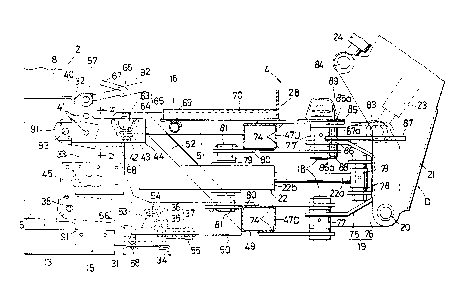
A tractor loader backhoe 1 includes a central tractor 2
having a front end detachably provided with a front loader 3
and a rear end detachably provided with a backhoe 4. In Fig.
10, instead of the backhoe 4, a rotary cultivator 95 is
connected to the tractor 2, by detaching the backhoe 4.
In Fig. 3, a tractor body 5 of the tractor 2 includes
an englne 5a, a transmission 5b, a steering front wheels lOF
and rear wheels lOR driven by the engine 5a. The engine 5a
is covered with a hood 6, and a steering handle 7 is
disposed at the rear portion of the hood 6. A hydraulic
device 8 for vertically moving a working machine is mounted
at a rear upper portion of the body 5, and an operator's
seat 9 is provided above the hydraulic device 8.
A front loader moun~ing table 11 is disposed on lateral
sides at a longitidinally intermeidate portion of the
tractor body 5, and a post 12 of the front loader 3 is
- 1 322q i 3
detachably provided to the mounting table.
The front loader 3 is detachably arranged at the front
portion of the tractor body 5. A boom 126 has a base end
portion pivotally supported to a tip end of the post 12, and
has a front end pivotally supporting a bucket 127. Further,
a boom cylinder 128 is disposed between the post 12 and the
boom 126, a bucket cylinder 129 is disposed between the
boom 216 and the bucket 127, and a brace 130 is disposed
between the post 12 and the front end of the vehicle body 5.
A pair of reinforcing frames 13 are provided at lower
lateral sides of the body 5. The reinforcing frames 13 are
directed in a running direction of the vehicle 5 and is
fixed to the vehicle body 5 through a plurality of brackets
14 each extending in the running direction or a lateral
member connecting the right and left reinforcing frames.
The front loader mounting table 11 is also fixed to the
front portion of the reinforcing frames 13, so that the
reinforcing frames 13 also support the front loader 3.
In Figs. 1 thru 3, an attaching frame 15 is fixedly
secured to the rear portion of the body 5, and a mounting
frame 16 provided at the rear portion of the backhoe 4 is
detachably ~ounted on the attaching frame 15. A pair of
right and left outriggers 17 are mounted on the mounting
frame 16 of the backhoe 4, and further, a swing frame 19 is
swingably provided through a vertical shaft 18. A boom 21
1 3~2993
is pivotally supported to the swing frame 19 through a
hori~ontal shaft 20. A swing cylinder 22 is disposed between
the mounting frame 16 and the swing frame 19. A boom
cylinder 22 is disposed between the swing frame 19 and the
boom 21.
An arm 25 movable by an arm cylinder 24 is pivotally
supported to a tip end of the boom 21, and a bucket 27
movable by a bucket cylinder 26 is pivotally supported to
the tip end of the arm 25. Each of the cylinders 22,
23,24,26 is controlled by a control box 28 mounted on the
mounting frame 16.
At the rear upper portion of the vehicle body 5,
disposed are attachment seats 29A,29B for providing two seat
positions. When the operator's seat 9 is attached to the
attachment seat 29A and the seat 9 confronts the
manipulation handle 7, tractor drive position 9A is
provided. On the other hand, when the operator's seat 9 is
attached to the attachment seat 29B and confronts the
control box 28, the backhoe maniuplation position 9B is
provided.
Incidentally, in the illustrated embodiment, the single
operator's seat 9 is selectively attached to one of the
attachment seats. However, the single operator's seat 9 may
be rotated to have two seat postures, or two operator's
seats may be provided for the attachment tot he attchment
-- 10 --
- . 1 322qq3
seats 29A 29B.
In Figs. 1 thru 7, the attachment frame 15 has a box
shape structure in which there are provided a pair of right
and left lower brackets 31, an upper bracket 32, an
intermediate bracket 33 connecting between upper portions of
the right and left lower brackets 31, and a linking plate 34
connecting between the lower portions of the right and left
lower brakets 31.
The right and left lower brackets 31 has a front upper
portion secured by bolt to the outer side surface of the
vehicle body 5 and has a front lower portion secured by bolt
to the rear end of the innser surface of the reinforcing
frame 13. The brackets also has a rear lower portion bent
into L shape secured by bolt to the linking plate 34 which
links right and left brackets. At outer side of the rear
lower portion of each of the lower brackets 31, right and
left lower linking portion 37 having a tapered configuration
is provided by welding a mountain shaped receiving member 36
to a rod member 35. This lower bracket 31 has a front
portion provided with a lower link connection pin 38
projecting laterally outwardly. The right and left lower
linking portion 37 and the lower link connecting pin 38
project lsterally outwardly from the vehicle body 3.
The right and left upper bracket 32 is secured by bolt
to the rear upper portion of the vehicle body 5 through an
229q3
attachment plate 40 welded to the front end portion. The
right and left upper brackets 32 are formed with a plurality
of pin holes 41 each extending in vertial direction at the
front end portion thereof for receiving the top link
conecting pins, so that the top link connecting portion is
provided. A distance between the rear portions of the right
and left upper barckets 32 is larger than the distance
between the front portions of the right and left upper
brackets, so that a valley shaped (V-shaped) receiving
member 43 is welded forproviding a tapered right and left
uppwer connecting portion 42. A guide plate 44 having
outwardly bulged shape is secured to the outer end of the
valley shaped receiving member 43. The right and left
connecting portion 43 has a width within the width of the
vehicle body 5, and greater than the width of the top link
connecting portion.
The intermediate bracket 33 has an arch shape at its
rear surface, and lower portion of the right and left side
walls are fixed to the lower bracket 31 by bolt. The
intermediate bracket 33 and the right and left lower bracket
31 serve as a PTO shaft cover which cover right and left
side and upper face of a PTO shaft 45 extending from the
back face of the vehicle body 5, and the upper portion is in
abutment with or fixed to the right and left upper bracket
32 and the lower end of the guide plate 44. Similar to the
- 12 -
- 1 3?2993
linking plate 34, the intermediate bracket 33 links together
the right and left lower brackets 31. If the bracket is
welded to or fixed to the upper barcket 32 by bolts, the
bracket also serves as a connecting member for reinforcing
the upper bracket 32.
The mounting frame 16 which constitutes a front portion
of the backhoe 4 includes a main frame body 49 having a
rectangular shape provided by a pair of upper and lower
angular pipe 47 and a pair ofright and left angle steels
positioned at both sides of the angle pipes. A right and
left lower plate 50 having increasing area in frontward
direction is protruded from the lower angle pipe 47D, a
parallel right and left upper plates 51 are protruded from
the upper angle pipe 47D, and a stabilizer 52 is disposed
betwen the intermediate portion of the right and left upper
plates 51 and the lower angle pipe 47D.
An angle member 53 is welded to the front internal
surface of the right and left lower plates 50, so that
provided is a lower coupling portion 54 adapted to be fitted
with the lower connecting portion 37. The coupling and
decoupling of the lower connecting portion 37 and the lower
coupling portion 54 can be made by the extension of a bolt.
Alternatively, a wedge member 56 can be used as a lower
locking means 55.
That is, as shown in Figs. 4, 5 and 7, the angle member
- 13 -
t 322~93
53 is formed with an insersion hole 57 for receiving the
wedge member 55, and has a front face welded to a wedge
member abutting rod 58, and has a rear face welded to a
wedge member guide sleeve 59. On the other hand, the wedge
member 56 is provided with a wedge portion 56a having a
slanting engaging portion 56c and a thread portion 56b.
When the wedge member 56 is inserted into the insertion hole
57, the wedge portion 56a abuts the wedge abutting rod 58
and the rod member 35 of the lower connecting portion 37, so
that the thread portion 56b projects out of the wedge guide
sleeve59. The projecting portion of the thread portion 56b
is fitted with a collor 60 and is engaged with a nut 61. By
the threading engagement of the nut 61, the slanting
engaging portion 56c of the wedge member 56a is depressed
against the rod member 35. Therefore, the lower conecting
portion 37 and the lower coupling portion 54 are fixedly
locked with each other without any looseness.
As shown in Figs. 1, 2, 6 and 7, the front portion of
the right and left upper plate 51 allow a single roundish
rod 63 to pass therethrough, and the rod 63 is fixed to the
plate. At end portions and at the lower sides of the rod
63, a valley shaped mount member 64 is fixed, so that the
upper coupling portion 65 to be coupled to the upper
connecting poriton 42 is provided. The upper connecting
portion 42 and the upper coupling portion 65 are locked with
- 14 -
1 322~93
each other by an upper locking means 66 which is provided
with a bolt 67 extending through the roundish rod 63 and the
valley shaped mount plate 64 and a nut 68 disposed at hte
valley shaped receiving member 64 for threading enagement
with the bolt 67.
The lower connecting portion 37 and the lower coupling
portion 54 and the upper connecting portion 42 and the upper
coupling portion 65 are provided with tapered face for taper-
fitting engagement with each other. Therefore, the tapered
face guides travel of forward and rearward direcitond during
fitting. Therefore, relative position between the tractor 2
and the backhoe 4 in frontward and rearward direction can be
corrected.
A pipe member 69 is disposed at an intermediate portion
of the right and left upper plate 51 in frontward and
backward direction. A step plate 70 is secured by the pipe
member 69 and the upper angle pipe 47U. The control box 28
is disposed at the rear upper portion of the step plate 70.
An outrigger supporting member 71 is disposed at an
outer edge portion of the right and left angle steels 48,
and a base portion of a cylinder for the outrigger 17 is
pivotably supported to the upper portion of the supporting
member 71.
The attachment frame 15 at the side of the vehicle body
5 and the mounting frame 16 at the side of the backhoe 4 are
- 15 -
~ 3~2sqs
separated from each other in such a manner that the
outrigger 17 of the backhoe 4 and the bucket 27 are in
contacts with a ground, and the backhoe 4 is self-standable.
By the retraction of the outrigger cylinder ~2, the upper
and lower coupling portions 65, 54 are moved toward their
decsent positions and engaged with the upper and lower
connecting portions 42,37, and are fixedly mounted by the
upper and lower locking means 66,55. Reversely, after
releasing the upper and lower locking means 66,55, the
cylinder 72 is extended, so that the upper and lower
coupling portions 65,54 are disengaged from the upper and
lower connecting portions 42,37, so that the tractor 2 and
the backhoe 4 are separated from each other.
When the backhoe 4 is disassembled from the tractor 2,
the three points linking mechanism 96 can be coupled to the
tractor 2 for mounting thereon a rotary cultivator 965, a
box blade, or other three point link working ~achine. Fig.
10 shows a state in which the rotary cultivator 95 is linked
to the tractor.
Althrough not described in detail with respect to the
rotary cultivator 95, the rotary cultivator 95 includes a
frame body 100 in which a transmission case 99 and a side
frame are fixedly secured. The transmission case 99 is
provided at outer ends of support arms 98 projecting
laterally from a central gear case. The cultivator also
- 16 -
t 322q73
includes a pawl shaft 102 provided with pawls 101, which
pawl shaft extends in horizontal direction and is rotatably
provided about its axis at a position below and between the
transmission case 99 and the side frame. A lower link
coupling portion 104 adapted to be connected to the rear end
of the lower link 91 is provided at the pair of right and
left brackets 103 extending frontwardly from the upper
portion of the frame body 100. Further, a top link coupling
portion 106 adapted to be connected to the rear end of the
top link 92 is provided at a support mast 105 projecting
upwardly and frontwardly. After the backhoe 4 is
disassembled from the tractor 2, at the front portion of the
three points linking mechnism 96, thelower link 91 is
connected to the lower link connection pin 38 of the lower
bracket 31, and the top link 92 is connected to the
connecting pin 9~ extending through the top link connection
pin hole 41. The intermediate portion of the lower link 91
is cooperatingly connected to a lift arm 108 of the
hydraulic device 8 through a lift rod 107.
Thus, the three point link working machine installed by
way of the three points linking mechanism 96 can be
installed while the attachment frame 15 is mounted on the
vehcle body 5.
Incidentally, if the backhoe 4 is installed to the
tarctor 2, the three points linking mechanism 96 can be
~ t3229q3
dispensed with, and therefore, the mechanism can be
disassembled from the vehicle body. However, if the tractor
2 has sufficient space for accommodating the mechanism,
particularly for accommodating the lower link 91, the
mechanism can be remained on the vehicle body. On the other
hand, if no suffic-ent space is provided, the front end of
the lower link 91 is engaged with the supplemental pin 93
provided at the rear upper side of the vehicle body 5 and
the rear end of the lower link is dipsoed within the angle
steel 48 as shown by a dotted chain line in Figs. 1 and 2.
Alternatively, the rear end is latched with the angle steel
48 by a fastening member, or the intermediate portion of the
lower link may be latched with a two or four posts so as to
provide sufficient working space.
In Figs. 1 thru 3, 8 and 9, the mounting frame 16 has a
pair of pivot plates 74 projecting rearwardly from the upper
and lower angle pipes 47U 47D, and a vertical shaft 18 is
roatably supported in each one of the pivot plate 74. The
swing frame 19 has a swing plate 75 having C-shape in side
view and a pair of supporting plate 76 welded to the outer
side of the swing plate and extending in a direction
perpendicular thereto. A boss member 77 is welded at the
upper and lower legs of the swing plate 75, and the boss
member 77 is fittedly secured to the vertical shaft 18
between the two pivot plates 74.
- 18 -
, 1322qq3
A pin support member 78 is fixed to the swing plate 75.
A tip end of the swing cylinder 22 is fittedly secured to a
pair of right and left swing pins 79 pivotally supported to
the pin support member 78.
A pair of right and left swing cylinders 22 are
provided. Upper and lower tranion shaft 79 protruding from
the main body 22b is provided rotatable about a vertical
shaft and is supported by a fixing plate 80 frontwardly
protruding from the upper and lower angle pipes 47U 47D
through a pivot boss member 81. the right and left swing
cylinder 22 is adapted to pivot the swing frame 19
rightwardly and leftwardly by an angle of ~0 to 80 degrees
with respect to a center CL of the backhoe 4. Therefore,
the swing frame 19 can be pivotally moved by an angle
ranging from 140 to 160 degrees.
The pair of right and left support plate 76 of the swing
frame 19 have lower portion securing the horizontal shaft
20, and have an upper portion pivotally supporting a boom
pin 83. The horizontal shaft 20 projects laterally from the
support plate 76 so as to pivot the bvase end of the boom
21. A may body of the boom cylinder 23 is supported to the
boom pin 83. Reference numeral 84 designates a pin for
attaching an arm cylinder 24 disposed at the boom 21.
The upper leg portions of the upper pivot plate 74 and
the swing plate 75 are provided with projecting portions 85
-- 19 --
t 322993
86 extending laterally outwardly from the vertical shaft 18,
and pin holes 85a and 85b are formed at the respective
projecting portions. The pin holes 85a and 86a are aligned
with each other when a center of the swing plate 75 is
coincident with the center CL of the pivot plate 74.
Further, a locking plate 87 is fixed to the side of the
boom 21. The locking plate 87 has a front portion provided
hole
with pin~87a. When the boom 21 is moved upwardly, the pin
is positioned between the projecting portions 85 and 86 of
the pivot plate 74 and the swing plate 75, so that a pin
hole 87a is coaxial with the pin holes 85a and 86a.
When the backhoe 4 is transported or accommodated within
an accommodation posture D, the center of the swing plate 75
and the boom 21 are in alignment with the center CL of the
mounting frame 16 and the pivot plate 74, so that the boom
21 has an approximately uppermost position with respect to
the swing plate 75. In order to maintain this state or in
order to maintain the position extremly close to this
position, thepin holes 85a 86a 87a are formed, and the
locking pin 88 is inserted into the pin holes oriented in
coaxial with each other. As a result, the boom 21 is
maintained at non-swingable and non-vertically movable
phase. The pin holes 85a 86a 87a and the locking pin 88
constitute in combination the lokcing means 89 for the
backhoe 4 for avoiding its swinging motion.
- 20 -
1 322`~q3
Incidentally, the locking plate 87 can be provided to
the boom 21 in such a manner that the locking plate is
positioned above the pivot plate 74 and extends in parallel
therewith when the boom 21 is at its accommodation posture.
With this arrangement, the locking means 89 cna be provided
at an extension of the center CL.
Figs. 11 thru 14 show a second embodiment according to
this invention. Description will be given particularly on
the distinguishing points relative to the first embodiment.
The attachment frame 15 includes right and left lower
brackets 31, right and left upper brackets 32, an
intermediate bracket 33 a linking plate 34 and a right and
left guide plates 44. The linking plate 34 provides a
bottom wall of a hitch box 109 bridging between the front
lower portions of the right and left lower brackets 31. The
right and left lower bracket 31 are not connected to the
reinforcing frame. The right and left upper brackets 32 are
spaced apart from the upper connecting portion 42 in
frontward and backward direction.
The right and left upper connecting portions 42 are
mounted on the intermediate bracket 33, and a receiving
member 43 is only attached to the guide plate 44. The
receiving plate 43 is constituted by a member having U-shape
in cross-section, and has a bottom portion provided with a
valley tapered in frontward and backward direction. The
- Z1 -
1 322~q3
right and left upper coupling prtion 65 and the upper
locking means 66 are identical with those used in the first
embodiment.
The relationship between the right and left lower
connecting portion 3~ and the lower coupling portion 54 is
the same as the relationship between the upper connecting
portion and the upper coupling portion in the first
embodiment. A valley shaped receiving member 11 is fixed at
the rear portion of the right and left lower brackets 31,
and a rod member 111 and the valley shaped rod member 112 of
the lower coupling portion 54 is fixed to the lower pate 50
of the mounting frame 16, and further, the coupling portion
54 is mountedly fitted from the upper portion of the lower
connecting portion 37 and is fixed by the lower locking
means 55. Incidentally, the receiving member 110 also
projects inwardly from the lower bracket 31.
The lower locking means 55 is provided at inner side of
the respective right and left lower plates 50. The lower
locking means is also provided with a wedge member 113
slidable in frontward and backward direction and having an
engaging tip face 113a, a spring 114 for biasing the wedge
member 113 toward the mount member 112, a handle 115 which
is gripped when the wedge member 113 is retracted rearwardly
against the biasing force of the spring 114, and a holding
portion 116 for holding the wedge member 113 at its
1 3~2993
retracted position when the wedge member is rearwardly moved
against the biasing force of the spring 114.
The wedge member 113 is supported by a guide sleeve 117
and a guide plate 118 those fixed to an inner side of the
lower plate 50, and the spring 114 is disposed over the
wedge-member 113 between a stepped portion 113b of the wedge
member 113 and the guide plate 118. The handle 115 is
disposed in a direction perpendicular to the wedge member
113, and the holding portion 16 is defined by a notch formed
at the lower edge of the lower plate 50 for detachably
engaging the handle 115.
When the handle 115 is disengaged from the holding
portion 116, in the lower locking means 55, the wedge member
113 is advanced through the spring 114, so that the
receiving member 110 is interposed between the wedge member
and the mount member 112. With the arrangement, connection
between the lower connecting portion 37 and the lower
coupling portion 54 i5 locked. When engaging with the
holding portion 116 after moving the handle 115 rearwardly,
this locking is released, so that the wedge member 113 is
held at its retracted position. Even if the lower locking
means 55 is positioned between rear wheels lOR of the
tractor 2, operation for releasing the locking can be easily
achieved. During locking enagement, the locking is tightly
provided since the wedge member 56 is urged in the inserting
- 23 -
1 322993
direction by the spring 114. Therefore, the backhoe 4 cna
be rigidly coupled to the vehicle body 5.
Figs. 15 thru 17 shows a third embodiment of this
invention wherein the lower connecting portion 37 is
identical with that of the first embodiment. However,
angle receiving member 36 extends below the rod member 35 so
as to provide a wedge receiving face 120 abuttable with a
slanding engaging portion 113a of the tip end of the wedge
member 113.
Further, the lower locking means 55 would be the same as
that of the second embodiment such that the wedge member 113
is slidably disposed in frontward and backward direction by
the guide sleeve 117 and the guide plate 118, and the urging
manner of the spring 114 toward the lower coupling portion
54 may be the same as the second embodiment. However,
remaining construction is different from the foregoing
embodiments.
That is, a pin 121 extends through the wedge member 113,
and a cam member 122 is pivotally secured by the pin 121. A
handle 115 is fixed to the cam member 122, and a guide
sleeve 117 fixedly secures a cam receiving plate 123 with
which a cam surface 122a of the cam member 122 and a holding
portion 122b are abutted. The cam member 122 is constructed
by coupling upper and lower cam plates pivotally supported
to the pin 121 by means of a vertical plate.
- 24 -
t 3229q3
The spring 114 is interposed between the pin 121 and teh
guide plate 118, so that the wedge member 113 is biasingly
urged leftwardly in Fig. 16 for engaing the slanting
engaging portion 113a with the wede receiving face 120.
When the cam member 122 is rotated in a counterclockwise
direction P in Fig. 15 through the handle 115, the cam face
122a is brought into abutment with the cam receiving plate
123, and the wedge member 113 is retracted against the
biasing force of the spring 114 for abutting the holding
portion 122b, to threby hold the wedge member 113 in its
retracted position. The handle 115 is outwardly protruded
from the lower plate 50 when the wedge member 113 is at its
retracted position, so that locking and lock releasing
operation of the lower locking means 55 is facilitated.
According to the third embodiment, since the cam member
122 provided at the tip end of the handle 15 is adapted for
locking and releasing the locking engagement, the wedge
member 113 can be easily released, even if the biasing force
of the spring 114 is high and the tight engagement is
provided between the slanding engaging portion 113a and the
wedge receiving face 120.
Incidentally, the present invention is not limitted to
the foregoing embodiments, but various modifications can be
made therein. For example, lower locking means 55 is used
for locking between the upper connecting portion 42 and the
~ 3~9q3
upper coupling portion 65, and the upper locking means 66 is
used for locking between the lower connecting portion 37 and
the lower coupling portion 54. The attachment frame 15 can
be provided by a pair of raight and left plate members and a
plurality of linking members connecting between the right
and left plates, and the upper and lower connecting portions
42 and 37, the top link connecting pin hole 41 and the lower
link connecting pin 38 can be provided at the pair of the
right and left plate members.
- 26 -