Note : Les descriptions sont présentées dans la langue officielle dans laquelle elles ont été soumises.
` ~323~2~
OPTICAL BEAM SCANNER FOR BAR-CODE
BACKGROUND OF THE INVENTION
1. Field of the Invention
The present invention relates to an optical beam
scanner used for reading a bar code from omni-directional
light beam patterns in a POS (Point Of Sales) system.
2. Description of the Related Art
The POS system is now widely used in supermarkets
and department stores for the sales management of goods and
to speed up the checkout operation.
This system comprises a beam scanner for scanning
a bar-code printed or attached to goods by a scanning light
beam and converting the detected optical information into
data suitable for computer-processing, a computer for
processing the obtained data, and a POS register for
connecting the beam scanner to the computer and displaying
the necessary information to a customer.
A "bar-code" is a combination of thin and thick
black lines and wide and narrow spaces; these being
variously arranged to represent a specific character,
numeral or symbol.
The bar-code is scanned by a beam scanner, such
as a wandl a laser scanner, or a CCD scanner, which detects
the variation of intensity of a light scattered by the bar-
code on which the beam is incident; and converts the same
to an electric signal.
Among known beam scanners, the laser scanner,
which comprises a means for displacing a laser beam across
a bar-code printed or attached to goods and moved laterally
over a window of the scanner housing by an operator, a
means for detecting a beam reflected from the bar-code,
including various intensity variations corresponding to
black and white areas on the bar-code, and a means for
converting an optical signal obtained *rom the detected
..
.
. .
.
' ~
~' ~
1 32342~
light intensity into an electric signal and decoding same
as bar-code information, is most widely used.
To raise the efficiency of the checkout
operation, an easily operable op~ical beam scanner must be
used. Particularly, the bar-code must be accurately read
even though a label carrying the bar-code is variously
disposed on the goods, so that it is not necessary for th~
operator to orient the bar-code label in only ~ne direction
during the scanning. This function is known as "omni-
directional readability".
To maintain the "omni-directional readability" at
a high level even when reading a bar-code based on
truncated symbols having bars approximately hal~ the length
of standard bars, the laser beam mu~t be scanned along
omni-directional scanning patterns; for example, in a
horizontal scanning line for reading bar-code symbols
oriented approximately in the horizontal direction, in a
vertical scanning line for reading symbols oriented
~0 approximately in the vertical direction, and in an oblique
scanning line for reading symbols oriented approximately in
a direction between the horizontal and the vertical.
Further the beam scanner must be compact, to
ensure a wider field of application to various checkout
systems currently used in the merchandising industry.
To obtain such omni-directional scanning
patterns, a beam scanner provided with a rotary mirror is
used. In this scanner, a laser beam projected from a laser
tube is d~lected by small mirrors and a large mirror and
received by a rotary mirror through a flat area of a
combination lens.
The prior art fixed type laser scanner must be
provided with a plurality of pairs of mirrors for
selectively deflecting a laser beam reflected by a rotary
mirror onto a plurality of flat mirrors arranged around a
rotary axis thereof. This type of beam scanner, however,
, :
' ~ '
~323~
is very expensive due to the need for a plurality of
mirrors, each of which must be manufactured and adjusted
with a high degree of skill and accuracy. In addition, the
intensi~y of the laser beam is dampened to a great extent
due to the repeated reflections by the mirrors, which
lowers the readability of the beam scanner. Conversely, if
a high grade mirror having a better reflective efficiency
is used to minimize this dampening of the beam intensity,
the manufacturing cost of the beam scanner is further
increased. Note, such a beam scanner is disclosed in, for
example, Japanese Unexamined Patent Publication (Kokai) No.
62-194586 and U.S. Patent 4,799,164.
SUMMARY OF THE INVENTION
Accordingly, a feature of one embodiment of the
present invention is tn eliminate the above drawbacks of
the prior arts and provide a bar-code scanner in which
omni-directional scanning patterns of a laser beam are
easily obtained by a simple optical system having a small
~O number of mirrors.
In accordance with an embodiment of the present
invention there is provided an optical beam scanner for
reading a bar-code, comprising: a beam generator for
projecting a laser beam along a fixed axis; a rotary mirror
rotatable about its axis and having a plurality of
reflection surfaces arranged in a polygonal manner on a
periphery of the rotary mirror, wherein the reflection
s~r~aces receive and reflect the laser beam, and wherein
each of the reflection surfaces includes an elongated
generally rectangular concave sur~ace that is generally
cylindrical about an axis so as to form a ridgeline having
an inclination angle relative to the axis of the rotary
mirror, the inclination angle of the xidgeline of each of
the respective reflection surfaces being different; means
for rotating the rotary mirror at a predetermined speed; a
housing accommodating the beam generator and having a
~ 32~2~
window positioned so that the laser beam is reflected from
respective reflection surfaces of the rotary mirror and
passes through the window.
The scanner according to a preferred embodiment
of the present invention is characterized in that each of
the reflection surfaces of the rotary mirror has a
configuration de~ined in such a manner that a direction of
a normal vector to the reflection surface is smoothly
1~ varied in one direction along a scanning line on the
reflection surface traced by sequentially incident points
of the laser beam across the reflection surface when the
rotary mirror is rotated, whereby the reflected beam traces
various linear scanning patterns, each corresponding to a
respective reflection surface, on a plane of the window
above which the bar-code is scanned.
Preferably each reflection surface is formed by
a part of a circular cylindrical surface cut out along a
height thereof in an elongated rectangular shape and
~0 disposed so that a ridgeline thereof is transverse to the
axis of the rotary mirror.
The beam scanner according to the present
invention also may comprise at least one additional flat
mirror, positioned after the rotary mirror, for directing
the laser beam reflected by the reflection surface in an
optional direction.
In the above beam scanner according to the
present invention, a lasar beam projected from the beam
generator along a ~ixed path is received by one of the
reflection surfaces of the rotary mirror and deflected
thereby at an angle corresponding to an angle of incidence
of the beam, which varies in accordance with the
inclination and curvature of a point on which the beam is
incident. The incident point is moved laterally across the
reflection surface as the rotary mirror is rotated at a
predetermined speed, whereby the angle of incidence of
` ~ `' , '
- ' -,: . :
. : `
: .
~2~
the beam is varied accordingly and the direction of the
beam reflect~d by the reflection surface is also gradually
varied. As a result, the reflected beam traces a linear
scanning pattern on the window plane, and since the
inclination and/or curvature of each respective reflectivn
surface is different, the linear scanning pattern depicted
on the window plane also has various gradients; whereby the
omni-directional scanning patterns can be obtained.
BRIEF DESCRIPTION OF THE DRAWINGS
The other features and advantages of the present
invention will be more apparent from the following
description with reference to the drawings illustrating the
preferred embodiments of the present invention, wherein:
Fig. 1 is a perspective view o~ a polygonal
rotary mirror used in a laser beam scanner according to a
first embodiment of the present invention:
Fig. 2 is a schematic front view of a reflection
surface of the rotary mirror, illustrating an inclination
angle thereof;
Figs. 3 and 4(a) through 4(c) are perspective
views, respectively, illustrating a principle of ~orming
omni-directional scanning patterns;
Fig. 5 is a schematic view of main parts of a
laser beam scanner according to a second embodiment o~ the
present invention;
Fig. 6 is a perspective view of a laser beam
scanner according to a third embodiment of the present
invention, illustrating the main parts thereof;
~O Fig. 7 is a perspective view of a prior art laser
beam scanner provided with a conventional rotary mirror
having a flat type polygonal reflection sur~ace;
Fig. 8 is a perspective view illustrating omni-
directional scanning patterns obtained ~rom the beam
scanner o~ Fig. 7; and
Fig. 9 is a representative illustration of a
:`
.
~323~
bar-code.
DESCRIPTION OF THE PREFERRED EMBODIMENTS
Prior to describing the preferred embodiments of
the present invention reference will initially be made to
Figs. 7 and 8 which illustrate prior art and Fig. 9 which
illustrates a typical bar-code.
As illustrated in Fig. 9, a bar-code is a
combination of thin and thick black lines 50, 51 and wide
and narrow spaces 52, 53: these being variously arranged
to represent a specific character, numeral or symbol.
A beam scanner provided with a rotary mirror is
illustrated in Fig. 7. In this scanner, a laser beam 2
projected from a laser tube 1 is deflected by small mirrors
5, 6 and a large mirror 9, and received by a rotary mirror
29 through a flat area 81 of a combination lens 8. In the
drawing, reference numeral 10 designates a scanner housing.
The body of the rotary mirror 29 has a conical
shape, and two flat reflection surfaces 29a are arranged on
the opposita slants of the cone, symmetrical with each
other relative to a central axis of the cone, so that the
reflection surfaces 29a are directed downward. The beam
incident on the reflection surface 29a is deflected to a
first mirror 15 disposed therebelow, and reflected thereby
to a second mirror 18 associated with the first mirror 15.
Note, usually a plurality of pairs of first and second
mirrors are provided, but only one pair is illustrated in
Fig. 7, to clarify the drawing. The beam reflected by the
second mirror 18 emerges from the scanner through a window
21, in an obliquely upward oriented direction. This beam
traces, for example, a horizontal scanning pattern e (see
fig. 8) on the window surface.
As the rotary mirror 29 is driven to rotate about
its axis by a not shown motor, the beam deflected by the
reflection surface 29a is received by anoth~r pair of firRt
and second mirrors, and traces another scanning pattern
,
, ,, , ., . : ' ., '
.
~3~
- 7 -
other than the horizontal pattern, and accordingly, omni-
directional scanning patterns a through e can be obtained
on the window surface. If more scanning patterns are
required, the number of pairs of first and second mirrors
can be increased accordingly. In Fig. 8, reference numeral
22 designates an imaginary vertical plane.
As shown in Fig. 7, a bar-code carried on a label
attached to goods 24 is moved across the window 21 and
illuminated by the laser beam tracing one of these omni-
directional scanning patterns. Part of the laser beam
scattered by the bar-code corresponding to black and white
areas thereof is returned to the scanner through the ~indow
21 and reflected reversely along the above-described path.
The returned beam is converged by the combination lens 8
and reflected by the large mirror 9 into a detector 28,
which detects the pattern of the intensity variation
containing the bar-code information. The intensity
variation is converted to electric signals by the detector
~0 28 and decoded as bar-code signals through a not shown A/D
converter and decoder.
As stated above, the prior art fixed type laser
scanner must be provided with a plurality of pairs of
~irrors for selectively deflecting a laser beam reflected
by a rotary mirror onto a plurality of flat mirrors
arranged around a rotary axis thereof. ~his type of beam
scanner, however, is very expensive due to the need for a
plurality of mirrors, each of which must be manufactured
and adjusted with a high degree of skill and accuracy. In
addition~ the intensity of the laser beam is dampened to a
yreat extent due to the repeated reflections by the
mirrors, which lowers the readability of the beam scanner.
Conversely, if a high grade mirror having a better
reflective efficiency is used to minimize this dampening of
the beam intensity, the manufacturing cost o~ the beam
scanner is further increased.
~3~3~
- 7a -
A beam scanner according to the present invention
is based on substantially the same principle as that of the
prior art beam scanner illustrated in ~ig. 7, except that
the first mirror 15 and the second mirror 18 are omitted
and a rotary mirror having a novel structure is provided
instead of the conventional rotary mirror. Accordingly, to
avoid repetition in the explanation, only the unique
constitution of the present invention will be described in
this specification.
As shown in Fig. 1, a polygonal rotary mirror 30
according to the present invention has a plurality of
reflection surfaces 30a~ 30b, ..., each arranged on a
respective outer side wall of a columnar mirror body 31
having a polygonal cross-section, such as an octagon. The
rotary mirror 30 is driven to rotate at a predetermined
speed about an axis 32 by a not shown motor.
Each reflection surface 30a, 30b forms a
concavity constituted by a part of an inner side wall of a
~0 circular cylinder. In more detail, each reflection surface
30a or 30b has an elongated rectangular shape which is cut
out from the circular cylinder along a height thereof and
disposed laterally to intersect with the rotary axis of the
rotary mirror 30. As illustrated in Fig. 2, a ridgeline
33a, 33b, i.e., a line connecting the deepest points of the
surface cross-section, intersects with the rotary axis 32
of the mirror 30 at an angle ~, viewed from the front, an
the angle ~ of one reflection surface is different ~rom the
angle ~ of another re~lection surface. According to this
structure, the direction of a normal vector to the
reflection surface is gradually varied as a point of
incidence of the projected laser beam 34 on the reflection
surface is moved along a scanning line.
To simplify the explanation, the laser beam 34 is
8- ~323~2~
assumed to be incident on the reflection surface in such
a manner that it intersects the rotary axis 32. If the
inclination angle ~ of the reflection surface 30a
relative to the rotary axis 34 is 90, as shown in
Fig. 3, a trace of the point of incidence of the laser
beam 34 forms a straight line X coinciding with the
ridgeline 33a or parallel thereto. Accordingly, the
incident beam 34 is reflected by the reflection surfaces
30a at an identical an~le. Note, a reflected beam 35
depicts a resultant scanning pattexn on a screen 36, as
sho~n by A in Fig. 3.
If the inclination angle D is other than 90, as
illustrated in Figs. 4(a) through 4(c), the point of
incidence of the laser beam 34 is moved along the same
scanning line X as above, as the rotary mirror 30 is
rotated. This scanning line X, however, is not parallel
to the ridgeline 33b of the reflection surface 30b, but
inclined thereto, and accordingly, the angle of inci-
dence of the laser beam 34 on the reflection surface 30b
varies from one point to another, whereby the reflected
beam 35 is graduall~ directed downward to trace a
scanning pattern B different from the scanning ~at-
tern A. As will be clear from the above description,
various scanning patterns can be obtained by varying a
magnitude and/or direction of the inclination angle 0.
Figure 5 is a schematic view of a laser beam
scanner according to another embodiment of the present
invention, in which a plurality of concave reflection
surfaces 41 are arranged on ~he inner wall of a cup
shaped rotary mirror 40. This structure enables the
size o~ the beam scanner to be reduced.
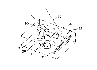
Figure 6 shows a third embodiment of the present
invention, in which an additional fla~ mirror 50 is
added to the structure of the first embodiment, after
the rotary mirror 30, for deflecting the beam reflected
by the rotary mirror 30 out of the scanner housing at a
desired angle ~, whereby the degree of freedom o
~ 9 ~ ~323~2~
machine design is enlarged.
The reflection surface of the rotary mirror may be
convex instead of concave, as described before, and in
the case of a convex reflection s~rface, thP inclination
of the scanning pattern is the reverse of that in the
case of a concave reflection surface. Also, the reflec-
tion surface may be constituted by a specific curved
surface other than a part of a circular cylinder.
As stated above, according to the present inven-
tion, a rotary mirror is provided with a plurality ofcurved reflection surfaces, each having a longitudinal
axis inclined to a rotary axis of the rotary mirror, and
thus it is unnecessary to provide a plurality of pairs
of flat mirror to obtain omni-directional scanning
patterns of the reflected beam. Accordingly, the
manufacturing cost of the beam scanner can be lowered
and the size of the scanner reduced.