Note : Les descriptions sont présentées dans la langue officielle dans laquelle elles ont été soumises.
` ~ 3 2 ~ 0 ~ ~
- 1 -
.
"AGRICULTURAL IMPLEMENT"
~ sackqround Art
: This invention relates to agricultural methods and
~ implements and is particularly concerned with an implement
,t~; 5 and method for soil amelioration.
Irrigation of clay soils presents particular problems
because of low infiltration rates. For instance
transitional red-brown earths and other heavy textured
soils give low yields of irrigated crops primarily due to
~; 10 low infiltration rates and hence reduced moisture storage.
McIntyre et al (Aust. J. Soil Res. 20, 81-90, 91-9)
have found that the rate of infiltration and increase in
~; depth of the wetting front is extremely slow in such
k soils. They suggest that this is largely due to the
15 presence of a "throttle" with very low hydraulic
~' conductively found below the soil surface. The presence
of this throttle also prevents the soil below it reaching
field capacity. In addition it creates inadequate
aeration in the upper layers.
Gypsum has been used to overcome this problem by
$ application to the surface. By this method infiltration
rates are increased as are crop yields. However regular
gypsum application is not widely used by farmers possibly
t due to the need for and cost of frequent applications,
25 which makes it uneconomic.
Furthermore it has been found that while deep tilling
can markedly increase infiltration rates and crop
productions on these soils, these effects tend to decrease
significantly over time, apparently due to repacking of
. 30 the soil under flood irrigation and tractor cultivation.
It is an objective of the present invention to
` provide an implement and method for producing deeper
wetting in clay soils during irrigation and improved
aeration in surface and subsurface layers.
It is a further objective to provide an implement and
~.~
... .
i.~
` ` 1324~3S
method which provldes longer term soil amelioration in such soil,
than has been achieved with currently available techniques.
The said invention is also used to overcome sub soil
acidity by the addition of lime and/or gypsum at rates ranging
from 2-60 tonnes per hectare in the described slots so as to
provide "zone of respite" from the high acidity. This allows
ir proliferation of healthy roots to depth, increases root length
, r
~ density, overcomes the problem of aluminium toxicity and allows
:~'
~s greater expression of the crop plants biological potential.
Disclosure of The Invention
The invention accordingly provides, in one aspect an
agricultural slotting implement for travel over a soil surface for
forming soil slots therein and comprising:
at least one rotatably driven slot forming device
mounted on said implement;
hopper means mounted on the implement and adapted to
store material to be supplied to the slot formed by each slot
~-.
~; forming device;
metering means for metering at a selected rate supplied
from said hopper means to each slot formed by the implement;
, ::
at least one shroud, each of said at least one shroud
enclosing an upper part of a respective one of said at least one
slot forming device to define an enclosing volume, characterised
in that where said implement is in operation, soil is sheared by
said rotating slot forming device and propelled upwardly to impact
the top and sides of the shroud to thereby cause working of the
., .
~; sheared soil and mixing of the sheared soil with any entrained
"
.,
~` 2
~':
~` D
,~`,.
:~:
::~
, ~ 1324035
material supplied from said hopper means, said shroud being
effective to deflect said sheared soil and any material supplied
. from said hopper means back into the formed slot.
Preferably the metering means comprises a pair of
''~''
~'
,'~
'~:
~,
~'
~i
~ r; ~
~'
'~
'~
.' ~
.~ .'
. ~''
. ~
:~'
l .
( .
. ':~
. 2a
. ~
". ~
. .,~ .
.. ,~
~- 'i;,
~ :
.
. ~
,.
~ .
` ~ 3 ~ 1~403S
contra-flighted augers located directly within the base of
the hopper with auger flights only being located above the
hopper outlets. A number of pitched elongated pegs may be
positioned on the auger bodies between the flights so as
to assist with movement of the material. We have found
that the use of small diametric pegs reduces power
~i requirements. In the case of an implement having a
single-slot forming means, a substantially vertically
disposed hopper may be used.
In a further broad aspect of the invention there is
provided a method of modifying soil drainage and/or
acidity comprising continuously mechanically shearing a
slot in the soil with a rotating rotor while supplying
preselected material, at a controlled feed rate, to the
soil and directing a mixture of soil sheared from the slot
` and the preselected material back into the slot.
The method is particularly well carried out by the
above described apparatus.
Preferably the preselected material is gypsum and/or
lime. Other organic matter such as chopped straw or rice
hulls may be added to the gypsum and/or lime so as to
assist in the stabilisation of the slot contents and hence
contribute to the longitivity of the effect.
Brief Description of ~rawin~
In order that the invention may be more readily
understood we shall describe a useful embodiment thereof
with reference to the accompanying drawings.
, Figure l is a side elevation view of an implement
according to the invention;
Figure 2 i8 a front perspective view of an implement
according to the invention;
Figure 3 i8 a rear view of an implement according to
the invention;
Figure 4 is a top plan view of the auger box used in
the apparatus of the invention;
.~
~ .A
.~
~" ~
~;
.~.
.~ .
` 3a 1324035
, . .
Figure 5 is a detailed view of a rotor used in an
:~ implement of the invention and a schematic diagram of the
process of slot formation and filling in accordance with
the invention; and
, 5 Figure 6 is a sketch of a soil profile showing gypsum
and/or lime enriched slot-~.
i
,~.
.,,
r
J
,'~
.'~ .
:,
" ,'
'~
.',~
'`"~J'
'~"
'.~
., ,
.
. g~ . !
'
`. A
'~
.~
.'
",
~ ,
,:'
.'
,_, ''
. .
.'~ ' `
~ , , .
... .
.'
1 3 2 ~ 5
. ..
; - 4 -
~est Mode of Carrvinq out the Invention
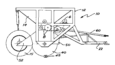
Referring initially to Figures 1 to 3, the implement
of the invention is designated generally by the
' numeral 10. It comprises frame 12 supporting a
hopper 14. Two spaced frame members 18 are pivotally
connected to the body of the frame at one end and mount a
~- wheel supporting axle 16 at the other. Wheels 15 are
^ mounted on axle 16.
~, At the front of the frame are disposed a pair of
frame members 20 which are fixed to the frame 12. Frame
members 20 are pivotally connected to a draw member 22
which can be attached to a tractor or other drawing
implement.
'~ A pair of hydraulic rams 17, located at the rear of
the frame, are pivotally connected at one end to the
~;~ frame 12 and at the other, to frame members 18.
Three slot forming rotor members 40 are supported
~ below the frame.
: ,~`
The rotor assembly consists of three lm diameter
rotors 40 mounted on a 3 metre long hollow shaft 42
supported at either end on heavy-duty roller bearings.
Rotors 40 are mounted on flanges disposed on the shaft.
. ~ Digqing blades 45 are alternately bolted (41) equally
spaced on either side of the periphery of each of the
rotors. It has been found that this arrangement provides
a maximum working depth of about 500mm. Details of this
~; rotor and blade assembly are shown in Figure 5.
.~.
Each rotor 40 is provided with a fixed shroud 50 and
an adjustable shroud 52. The adjustable shroud ensures
~, 30 deflection of the soil sheared by each rotor back into the
~:~
respective slots formed in the soil. Adjustment of the
~' shroud alters the amount of work done on the entrained
,~ soil and hence varies particle size.
The implement is driven by the power take~off
(approximately 540 r.p.m.) from the rear of a tractor via
7 -
~ ,A ~
~ 1324~3~
:
- 5 -
a splined driveshaft 60 and a multi-plate drive clutch to
a right-angle drive gearbox 65 and a heavy-duty
jackshaft 70. The jackshaft transmits power from the
gearbox to a side chain drive (30mm pitch) totally
enclosed in an oil-tight chain case 72 which may be an
inteqral part of the main frame.
Rotational speed of the rotors is varied by either
changing the two sets of pick off gears within the gearbox
or by altering the ratios between the driver and the
driven sprockets in the chain case. In this particular
example a rotor speed of 94 r.p.m. is used.
Although the power unit in this embodiment is
separate from the implement itself it will be clear to the
-, reader that the implement may include its own power
~` 15 drive. Further it will be clear an hydraulic drive system
~` or the like may be used to drive the rotor(s).
The spacing of the slots produced by the implement
can be adjusted by changing the spacing between the
~; rotors 40. The width of each slot can be adjusted by
altering the dimensions and~or configuration of the rotor
blades. For initial field testing 3 rotors spaced
`~; 1.2 metres apart and cutting a lOOmm wide slot were used.
-~ The depth of slotting can be varied by lowering or
raising the rotor assembly via hydraulic rams 17. Rams 17
may be connected via a pressure compensating valve to
ensure that the machine maintains a horizontal attitude.
~- Adjacent slots of different depths may also be created by
using rotors of different diameters.
~ Hopper 14, in this particular embodiment, is
`~ 30 dimensioned to give a pay load between 4 to 6 tonnes.
Experimentally by-product gypsum is used, althouqh other
forms of gypsum may be used. By-product gypsum is capable
of bridging over ~ gap of 480mm and thus presents problems
in achievinq a sa:isfactory feed rate. The hopper ba~e
has the dimensions of 500 x 3000mm to prevent such
.
~,
,.
/
~ 132~0~
bridging. Traditionally gypsum and/or lime hoppers have
sides sloping at 70D to decrease adhesion. As with the
auger box used in this embodiment, such a slope would have
resulted in a very high machine to achieve the design pay
5 load. Accordingly a hopper having a side wall angle of
45o was used. The hopper lining was fabricated from 306
gauge stainless steel sheets to provide smooth flow of
gypsum and/or lime. It is to be emphasised that the
hopper of the invention is not restricted to these
10 dimensions or configuration.
The physical flow properties of gypsum, particularly
} by-product gypsum are such as to create problems with
metering and distribution due to compaction and bridging.
To overcome this a gypsum and/or lime metering and
~ 15 distribution system was designed to maintain constant
,-.~, .
supply to the three rotors 1.2 metres apart at a minimum
rate of 4kg/min/rotor. This leads to application of
~- gypsum and/or lime at 4tha-l. $raditional belt and gate
gypsum and/~r lime spreaders may be used but accurate flow
20 rates at very low application may be difficult due to the
tendency for the belt to slip under the gypsum and/or lime
mass at the very small gate opening required. Screw
conveyors are traditionally used for uni-directional
transport of gypsum and~or lime for example from bulk
25 hopper to free-flow end delivery. This arrangement is
satisfactory for high-flow rate but requires complicated
speed-reduction gears for low rates.
The embodiment employs a much simpler gypsum and/or
lime distribution system which comprises two adjacent
,. :
30 250mm contra-flight augers rotating within an auger box
located directly beneath the hopper. A detailed view of
the arrangement is shown in Figure 4.
Three pairs of adjustable outlets 87 (Fig. 4) are
proviled in the bottom of the auger box, one pair over
35 each otor. The auger pitch used is 200mm but only that
i~'
'` ~'s'`
.,,
:j
.,
~ 13240~S
part of the augers 93 and 94 located directly above the
outlets are flighted. To overcome the problem of blockage
by small lumps of gypsum, a 12mm diameter rod is welded to
the auger-flight directly above the adjustable outlets to
sweep them during each rotation of the augers. A series
of 12mm pegs 97 are welded to the SOmm auger tube at a
spacing of 80mm with 200mm pitch. This peg arrangement
moves sufficient material to ensure the flighted lengths
of auger are kept full while there is gypsum and/or lime
in the auger box, but enables the auger to "slip" through
the gypsum and/or lime as the load increases. At the ends
of both augers straight flights 98 are installed to assist
' transfer of material between the augers. Immediately
~3~ after the straight flights one reverse pitch is installed
to further aid transfer of gypsum and/or lime between
augers and to counteract any tendency to pack against the
end walls.
,.,
A third agitator to prevent bridging or tunnelling is
located above the two distribution augers. This has a
~- 20 similar peg flight arrangement configured to move gypsum
and/or lime towards the three outlets. The augers and
agitator are powered hydraulically by a hydraulic motor 6
which at the maximum output of the hydraulic pump of 69
litres per minute and 175 bar on a Deutz NDX7.10 A"
~` 25 tractor, gives 94 r.p.m. This speed is mechanically
reduced via a system of chains and sprockets 8 to give an
auger speed of about 6.5 r.p.m. at full flow. Further
-, reduction is possible by means of a flow divider bypassing
the flow of oil to the return lines.
The gypsum and/or lime application rate may be
adjusted by changing the rotation speed of the augers and
the size of the openings 87.
In operation, power is supplied to the rotors from
the power take off of the tractor via the power
transmission system and rotor assembly. The frame
.
-
$
,
~'
3,
~ 132~3~
- 8 -
assembly is lowered by contracting rams 17 until the rotor
~; blades contact the soil. Thereafter the rotors are
lowered until the desired slot depth is achieved. The
implement is then pulled forward by the tractor along the
5 tract of land to be slotted. The hydraulically operated
; gypsum and/or lime system is adjusted to provide the
desired amount of gypsum and/or lime to the slots formed
in the soil. Soil scoured out by the rotors rotating in
either direction is pushed into the air however shrouds S2
10 ensure that this material, and any entrained gypsum, is
; deflected back into the slot.
Figure 5 provides a diagrammatic sketch of the
process of slot formation and refilling of the slot. The
~: thickness of cut (TC mm) is dependent on the tractor speed15 (St kmhr-1), rotor speed (S ~ rpm) and the number of
blades per rotor (N) and can be determined using the
equation
.
~'
TC - lO~St
: 60S ~ N
,
., .,
due to the forward movement of the tractor during slotting
the cutting arc of the forward rotating rotors (and hence
; 25 the slot face) will be shallower and fragment size larger
as the tractor speed increases or the rotor speed
,; decreases.
It has been found that the technique of this
invention results in soil having deeper wetting properties
30 during irrigation and improved aeration in the surface and
sub surface layers. This causes an increase in the
s phenological development, tillering, canopy closure and
yields of for example wheat crops. The rate of
~- con~olidation of the slots is likely to be slower than for35 deep tilled soils, owing to the weight of the tractor and
.
.~`
hl
r
S
~ 132403~
,5
implement during subsequent trafficking of the land, being
. largely borne by the undisturbed soil which has a higher
'f resistance to compaction.
'f Preferably the slotting mechanism creates narrow
slots with the adjacent soil undisturbed, to provide the
high bearing capacity to protect the slot from
' recompaction under the trafficking. The slot should be
- wide enough to allow rapid water entry and to provide
::s
internal drainage depending on the soil type and crops.
~ lO However it is desirable to keep the slot as narrow as
- possible to reduce power requirements and to maximise
protection of the slot from recompaction. The depth of
` the slot should be sufficient to penetrate the "throttle"
to provide water entry and aeration of the upper horizons,
where the major portion of the roots occur. A
~; diagrammatic representation of the slotted-soil profile is
~ shown in fiqure 6 in which layer A is sandy clay loam
.'''f. typically lScm deep, 8 is heavy clay sub soil, and C are
~` gypsum and/or lime enriched slots typically 15cm wide. It
is also desirable to minimise the depth to reduce power
`~-; requirements. For example a slot depth of 400mm was found
to be sufficient in field plots in sodic red brown earth
soil to cope with prolonged adverse conditions. In acid
soil conditions on the east coast of Australia a depth of
800mm has been achieved for maximum benefit.
The direction of rotation of the rotor is selectable
~, so that optimum operation may be obtained in various
situations and according to particular needs of each
individual job.
~;i 30 Although the invention has been described with
reference to a particular embodiment it will be clear that
modifications to the actual construction of the device may
be made without departing from the spirit and scope of the
invention. For example, although the invention has been
described in relation to an implement having throe slot
s,
,~
..
. ~ 132~3~
,, - 10 -
!~ '
~,. forming means it will be clear that the number of such
means can be varied. For example one, two, or more than
three slot forming means may be incorporated into the
device of the invention.
A.
~.,
.
'.
~,
~,
l .
,~,:,,
.~...
~ ,
'~'''
.~
~ .
~'
~'
~. ~..'.'r~
,",~ ~ ,j.
~, -
~, ~, . ~ ,
~,
~;,