Note : Les descriptions sont présentées dans la langue officielle dans laquelle elles ont été soumises.
f~ \ --1--
1324121
4-186 CVE-357
VALVE OVERRIDE MECHANISM
DESCRIPTXON
Backqround
The present invention relates to an improved
mechanism for connection to an actuator for a valve or a
choke which can be operated mechanically to cause the
5 reversal of the position of the valve member.
U. S. Patent No. 4,194,718 Baker et al is an example
of the prior art of such override mechanisms as applied to
a choke and which can be operated by a handwheel. It
includes means for releasably connecting the manual
10 operator to the gate to manual~ly move the gate and for
releasing the manual operator from the gate to allow such
movement.
U. S. Patent No. 3,378,224 to Boyle discloses a gate
valve which is piston actuated together with a handwheel
15 having a sleeve threaded on the shaft which extends
through the piston. Rotation of the handwheel causes
movement of both the piston and the valve member.
U. S. Patent No. 4,189,980 discloses a manual control
apparatus which has a split drive nut and a camming system
20 which coacts with the rotation system for bringing the
split drive nut into engagement with the threaded drive
screw and rotating the split nut to move the drive screw
and the valve member connected theretoO
U. S. Patent No. 3,628,397 discloses a valve member
25 having a ball nut secured to the uppPr portion of the
piston and a ball shaft secured to the top of the bonnet
and mounted so that its rotation causes movement of the
piston and valve member. During normal operation,
movement of the piston will cause rotation of the ball
30 shaft.
~ , ~' .
~P-~ 1324121
-2- 658~5-368
U~S. Patent No. 4,213,480 discloses an override
mechanism for a valve in which a nut is threaded onto the drive
stem and is engaged by a drive sleeve which telescopes onto the
nut and splines connect the sleeve to the nut. Rotation of the
sleeve rotates the nut which contacts one of the abutment surfaces
and then causes movement of the gate.
Summary
The improved override s-tructure Eor a valve includes an
override stem having means on its -Eirst end for connecting to the
valve member stem, an actuator -threaded onto the override stem for
moving the override stem axially to cause movement of the valve
member between open and closed positions, means for preventing
rotary movement of said actuator, means on the other 0nd of the
override stem for imparting rotation to the override stem within
the actuator, such rotation causing axial movement of the override
and valve member stems to move the valve member without movement ;
of the actuator. Anti-rotation pins are provided in said rotary
preventing means and to prevent relative ro-tation be-tween the
rotation imparting means and the override stem. ;~
The present invention offers the advantage of an
improved override mechanism for a valve which is easy to operate.
Another advantage is the provision of an improved
override mechanism for a valve which may be used to operate the
valve independent of the position and condi-tion of the actuator.
The invention further offers the advantage of an
improved valve with an override mechanism which does not interfere
with normal valve operations and yet is simple to use to control
the valve position.
.,, , ; ~ .
3 2 4 1 2
-2a- 65845-368
In one aspect, the invention provides a valve comprising
a body having an inlet, an outlet, a valve chamber in
communication with the inlet and the outlet, a valve member
positioned in said valve chamber Eor moving therein to open and
close flow be-tween said inlet and sald outlet, an actuator having
a moving portion and a non-moving portion, a stem connecting f:rom ~:
said valve member to said moving portion o:E said actuator, means
for preventing rotation of the moving portion of said actuator and
driving means connected to the outer end of said stem for rotating
said stem, characterised in that the stem has a portion which
extends through the moving portion, the connection between said
stem and said moving portion of said actuator is a threaded
connection, and the stem portion is arranged such that it can move
axially with the moving portion or be rotated in relation thereto
by operation of said driving means, the arrangement being such
that rotation of said stem within said moving portion of said
actuator causes axial movement oE said stem and said valve member ~:~
with said moving portion remaining in its axial position.
A further aspect of the invention provides a valve
override mechanism for a valve including a pressure responsive
actuator having a piston, an override stem having means for
connecting to a valve member stem, a driving means for rotating
the override stem, said override stem being in threaded engagement
through the piston of said actuator, and means -for preventing
rotation of the piston of said actuator whereby rotation of said ~ :
override stem by said driving means threads said stem through said
piston of said actuator and mo.ves the connection to the valve
member stem, means providing a s-top to the axial movement of said
"~
~324121
-2b- 658~5-368
override stem responsive to its rotation, a pair oE stops for
engaging with said override stem to limit the axial l~ovement
thereof responsive to its rotation, said rotation preventing means
includes said actuator having a non-rotating head, at least one
anti-rotation pin position in facing slots in the piston and the
non-rotating head of the actuator to prevent rotation of the
piston of the actuator, a shoulder on said stem, an internal
shoulder on said actuator, said stem shoulder adapted to engage
said internal actuator shoulder at the desired end of its axial
movement responsive to rotation in one direction, a stop surface
on said driving means, and means connecting said driving means to
said non-moving portion of said actuator, the end of said stem
engaging said stop surface on said driving means at the desired
end of its axial movement responsive to rotation in a direction
opposite to said one direction, rotation of said stem within said .
piston causing axial movement of said stem. -~
'; '
r !
. . ' . . , ' ~ : . .
. .;
-3-
1324121
Brief Descri~tion of the Drawings
These and other objects and advantages of the present
invention are hereinafter set forth and explained with
reference to the drawings wherein:
5FIGURE 1 is an axial sectional view of the improved
override mechanism of the present invention which is in
one position.
FIGURE 2 is another axial sectional view o~ the
override mechanism shown in FIGURE 1 but with the
10 mechanism in its opposite position to illustrate the axial
movement which may be imparted to a valve member when the
mechanism is operated independently of the actuator.
FIGURE 3 is a sectional view of the anti-rotation
pins used to prevent rotation of the actuator piston
15 responsive to rotation of the stem.
FIGURE 4 is a sectional view of the anti-rotation
pins between the drive sleeve surrounding the override
stem and such stem.
FIGURE 5 is a sectional view of a valve having the
20 improved override mechanism attached to and controlling
the operation of the valve stem.
Description of the Preferred Embodiment
Improved override mechanism 10 of the present
25 invention is shown in FIGURES 1 and 2 in its two extreme
positions. The components thereof are described with
respect to their position as shown in FIGURE 1 initially
and then their change of position is described with
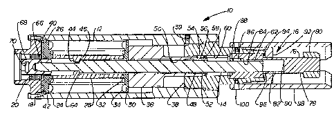
respect to FIGURE 2. Mechanism 10 includes actuator 12,
30 override stem 14, mechanical driving means 16 and lowèr
head 18 on which actuator is mounted and which includes
internal threads 20 for connecting to a valve 22 as
hereinafter described with respect to FIGURE 5.
,, . ~
-~ 4
- 132~121
Actuator 12 is shown to be a pressure responsive
actuator but may be any other type of actuator such as a
mechanical, electrical or other suitable type of actuator.
Actuator 12 includes cylinder sleeve 24 which is suitably
5 secured and sealed to the lower head 18, lower annular
spring plate 26, inner sleeve 28, upper annular spring
plate 30, springs 32 and 34, piston 36 and upper head seal
member 38 which is threaded into and sealed within the
upper interior of sleeve 240 Port 39 extends through
10 sleeve 24 into the annular space between the upper
surface of piston 36 and the lower surface of head 38.
Lower annular spring plate 26 is supported within sleeve
24 by snap ring 40 which is positioned within groove 42 on
the interior of sleeve 24. The interior of inner sleeve
15 28 includes inward projection 44 forming upwardly facing
shoulder 46. Upper annular spring plate 30 abuts against
the lower end of piston 36 so that the force of springs 32
and 34 are exerted thereon to bias piston toward its upper
position. Piston 36 includes annular upwardly extending
20 sleeve 48 which includes internal threads 50 which are in
engagement with threads 52 on the exterior of override
stem 14. Anti-rotation pins 54 are secured partially
within external axially extending slots 56 on sleeve 48 by
snap ring 58 and partially within axially extending slots
25 60 on the interior of upper head seal member 38 to prevent
rotation of piston 36 with the rotation of override
stem 14. The relationship of pins 54 with respect to
sleeve 48 and member 38 is best seen in FIGURE 3.
Override stem 14 includes threads 52 which engage
30 within threads 50 on the interior of piston sleeve 48l
upper axially extending slots 62, lower downwardly facing
shoulder 64 and lower threads 66 which engage valve member
coupler 68. Valve member coupler 68 includes lower
transverse slot 70 in which a circular T-shaped projec-
..
- ~
. : .. : ~, ; ~ , .. :
~-~ 5
~ ;~ '2 ~ 1 r~ 1
tion 72 of valve member stem 74 engages to provide the
connection between override stem 1~ and valve member
stem 74. Projection 72 and valve member stem 74 are seen
in FIGURE 5.
Mechanical driving means 16 includes driving
member 76 having outer solid portion 78 on which suitable
engaging means 80, such as a hex nut is engaged, and
sleeve portion 82 which includes inner slots 84 in which
anti-rotation pins 86 are positioned and held therein by
10 snap ring 88 and upper stop surface 90 formed by solid
portion 78 within sleeve portion 82. A handwheel or a
remote operated vehicle is slipped into enga~ement with
engaging means 80 and then driving means 16 is rotated~
With reference to the outer end of stem 14, and presuming
15 right hand thread engagement between stem 14 and piston
sleeve 48, a counter clockwise rotation will cause stem 14
to thread upwardly through piston sleeve 48 to move valve
member of valve 22 to its upper or other position without
any movement of piston 36. This movement is stopped by
20 the engagement of the outer end of stem 14 with stop
surface 90. If the movement of stem is clockwise, then it
will thread downwardly through piston sleeve 48 until stem
shoulder 64 comes into engagement with inner sleeve
shoulder 46. Cap 92 is threaded onto the outer end of
25 upper head seal member 38 and has outer inwardly extending
flange which closely surrounds the exterior of sleeve
portion 82 of driving means 1~. Suitable bearing means 94
is provided between the interior of cap 92 and outwardly
facing shoulder 96 on sleeve portion 82 of driving
30 means 160 Skirt 98 is secured to head member 38 by
threaded pins 100 and extends outwardly in surrounding
relationship to driving means 16 for protecti~n thereof
but spaced sufficiently radially outward from engaging
. . : . .
. : : . ,: . . : . - . ; :
~ 6-
132412~
means 80 to allow reasonable engagement thereof by a
handwheel hub or a remotely operated tool (nok shown).
Valve 22 includes body 102 having ports 104 and 106
defining the inlet and outlet of valve 22 and
5 communicating with valve chamber 108 in which valve
member or gate 110 is positioned between suitable sealing
bushings 112 for movement so that its port 114 either
registers with ports 104 and 106 to allow flow through
valve 22 or is out or registry with ports 104 and 106 so
10 that is blocked by valve 22. Bonnet 116 is secured to
body 102 and threads into threads 20 on the interior of
lower head 18. Valve member stem 74 is secured to
gate 110 and includes T-shaped projection 72 which
engages within slot 70 in valve coupler member 68.
During normal operations, actuator 12 functions
responsive to pressure fluid and spring force to move
gate llO to its desired position at all times. If at
anytime actuator 12 fails to function properly a handwheel
or a suitable tool of a remote operated vehicle (for
20 underwater applications) can be engaged with engaging
means 80 and then the proper rotation of driving means 16
will rotate override stem 14 to cause gate 110 to move
within valve body 102 to its desired position. The
engagement of the outer end of stem 14 with stop
25 surface 90 provides the indication that gate 110 has
completed its movement in one direction and the engagement
of stem shoulder 64 with shoulder 46 on inner sleeve 28
provides the indication that gate 110 has completed its
movement in the opposite direction. It is noted that this
30 mechanism is easy to operate and provides a positive
movement of the valve member even under conditions in
which the actuator piston has become locked in its
position. This mechanism is easy to operate under water
as a diver can readily attach a handwheel and rotate it to
. 7
` ~32~121
. :
change the valv~ position or an ROV may engage and operate
the mechanism easily and quickly.