Note : Les descriptions sont présentées dans la langue officielle dans laquelle elles ont été soumises.
~32~2~
CAMERA APPARATUS FOR MAGNETICALLY RECORDING ON EILM
CROSS REFERENCE TO RELATED APPLICATIONS
Reference is made to the following commonly
assigned copending applications:
1. U.S. Patent No. 4,947,196, entitled
CAMERA APPARATUS FOR MAGNETICALLY RECORDING ON FILM,
and issued August 7, 1990, in the names of ~ichael L.
Wash and Conrad Diehl.
2. U.S. Patent No. 4,996,546, entitled
CAMERA APPARATVS FOR MAGNETICALL~ RECORDING ON FILM,
and issued February 26, 1991, in the names of Daniel
M. Pagano and Robert P. Cloutier.
3. V.S. Patent No. 5,005,031, entitled
CAMERA APPARATUS FOR MAGNETICALLY RECORDING ON FILM,
and issued April 2, 1391, in the name of Richard R.
Relbe.
4. WO Publication No. 90/04214, entitled
FILM INFORMATION EXCHANGE SYSTEM USING DEDICATED
MAGNETIC TRACKS ON FILM and published April 19, 1990,
in the name of Robert P. Cloutier et al.
5. U.S. Patent No. 4,855,773, entitIed
MOTOR-DRIVEN FILM TRANSPORT APPARATUS, and issued
August 8, 1989 in the name of Donald M. Harvey. U.S.
Serial No. 221,955 is incorporatéd into this
application by reference.
6. WO Publication No. 89/12894, entitled,
as amended, THREE PART DECODER CIRCUITt and filed
December 18, 1989 in the name of Michael L. Wash.
7 U.S. Patent No. 4,912,467, entitled, as
amended, THREE PART ENCODER CIRCUIT, and issued March
27, 1990 in the names of Arthur Whitfield and Michael
L. Wash.
8. U.S. Patent No. 4,876,697, entitled, as
amended, THREE PART DECODER CIRCUIT, and issued
~5 October 24, 1989 in the name of Arthur Whitfield.
~32~2~
9. WO Publication No. 89/12892, entitled
METHOD FOR MODULATING A BINARY DATA STREAM, and
published December 28, 1989 in the name of Michael L.
Wash.
10. U.S. Patent No. 4,878,075, entitled
CAMERA APPARATUS FOR PREVENTING DOUBLE EXPOSURE and
issued Qctober 31, 1989, in the name of James W.
Cannon.
TECHNICAL FIELD
This invention relates to magnetic recording
apparatus for cameras and more particularly, to
magnetic recording apparatus for photographic still
cameras.
BACKGROUND ART
In commonly assigned WO Publication No.
90/0421~ entitled FILM INFORMATION EXCHANGE SYSTEM
USING DE~ICATED MAGNETIC TRACKS ON FILM, and
published April 19, 1990, in the name of Robert P.
Cloutier there i5 disclosed a photographic film
having a ~irtually transparent magnetic coating
covering the non-emulsion side of the film and
dedicated recording areas on the coating for
recording information such as film type, film speed,
film exposure information and information relevant to
the processing and subsequent use (e.g. printing) of
the film. The system thus provides for recording of
information during film manufacture, reading and/or
recordiny of information during camera use, and
reading and/or recording of printed related
information during photofinishing. In the
aforementioned copending application it is
specifically proposed that camera information be
recorded in spaced tracks preferably outside the
image area along the edge of the film.
Reading and writing information on a
132~
magnetic coating or stripe on photographic film in a
still camera requires solutions to problems different
than those encountered in other apparatus. Perhaps
the most significant problem is the space limitations
in a portable hand held still camera which
necessarily must be as compact and light as possible
to appeal to the average consumer. Perhaps equally
significant, however, is the characteristics of
photographic film relative to more common recording
mediums such as magnetic tape. Because photo~raphic
films are stiffer then magnetic tape and have varying
degrees of curl both in the longitudinal and
tranverse directions depending upon the base
materials and number and nature of sensitizing layers
and environmental conditions, they present unusual
problems in reading and writing information on a
magnetic coating or stripe. To provide a reliable
read or write signal the magnetic head must remain in
close proximity to the magnetic coating. Any
disturbances such as variations in film curl can ~ary
the relationship of the head to the coating and
decrease the reliability oE the signal.
Another problem unique to compact
photographic still cameras is that film advance
occurs in a short period of time with a limited
amount of motion and does not allow the steady state
conditions normally associated with magnetic
recording. Recording and playback must take place
during transient conditions which tend to separate
the film from the recording head. For optimum
magnetic recording during these conditions, the
magnetic head must maintain contact ~i.e. within 10
micro-inches) with the magnetic coating.
Techniyues for maintaining the desired
relationship of the head to a magnetic coating in
.
~ 32~S2~
other apparatus, are not practical for use in a
photographic still camera particularly a compact 35mm
camera. For example, in a sound movie camera, a film
having a magnetic stripe along one edge is typically
moved over a drum and information is recorded by a
magnetic head positioned in close proximity to the
drum. The drum provides a rigid support for the
film, removes film curl and assures a uniform head to
film relationship. While a fi~ed support such as a
sound drum produces satisfactory results, the space
limitations in a photographic still camera render it
impractical. Also, it is not suitable for the
transient conditions described above.
Also, in a still camera system, it is
desirable to record information pertinent to and
coincident with images because negatives are cut up
in photofinishing. In sound movie cameras, recorded
information is displaced from the image to achieve
continuous motion of the film during recording as
compared with intermittent motion during exposure.
The prior art relating to recording on
photographic film thus generally teaches providing a
support for the recording medium on the side opposite
from the recording head and continuous motion of theS recording medium to ensure reliable recording.
DISCLOSURE OF THE INVENTION
In accordance with the invention, magnetic
recording on a photographic still camera is achieved
in a simple, reliable manner by providing an opening
in a film cartridge lip in which a magnetic head is
received. Portions of the lip and light sealing
material within the lip provide a complient support
for the head and control for transient film curl to .
insure reliable magnetic coupling between the head
and magnetic surface of the film.
1324~2~
BRIEF DE:SCRIPTION OF THE DRAWINGS
Other advantages of the invention will
become apparent from the following description taken
in connection with the accompanying drawings wherein:
FIG. 1 is a cross section of a portion of a
conventional photographic still camera illustrating a
magnetic recording apparatus in accordance with the
invention;
FIG. 2 is a perspective view of the back or
10 door for the camera illustrated in FIG. l; -
FIG. 3 is a cross section taken
perpendicular to the section shown in FIG. l;
FIG. 4 is an enlarged cross section of the
film cartridge shown in FIG~ 1 illustrating the head
mounting;
FIG. 5 is an enlarged top view of the film
cartridge shown in FIG. 1 with the film partially
withdrawn;
FIGS. 6A and 6B are perspective views
showing cartridge variations;
FIG. 7 is an enlarged top view of the head
and flexure assembly;
FIG. 8 is an end view of the apparatus shown
in FIG. 7; and
FIG. 9 is a side view of the apparatus shown
in FIG. 7.
~EST MODE OF CARRYING OUT THE INVENTION
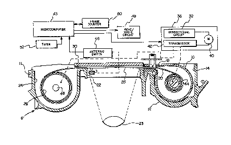
Referring to FIGS. 1, 2 and 3 of the
drawings, there is shown a portion of a typical
photographic still camera 6 having a back or rear
door 8 (FIG. 2) pivotal to an open position by means
of a pair of pins 10 one of which i5 shown in FIG.
: 2. The pins 10 are received in holes in frame 12.
Since such cameras are well known in the art,
features not necessary for an understanding of the
.~ .
:l~2~2~
--6--
present invention have been omitted or shown in block
diagram to simplify the disclosure.
The camera 6 comprises a frame or housing 12
having a chamber 14 at one end thereof for receiving
a film cartridge 16. The cartridge 16 which is shown
more clearly in FIGS. 4 and 5, preferably takes the
form of the film cartridge disclosed in the
referenced U.S. Patent No. 4,855,773 having a lip 18
from which a film 20 is removed for exposure. The
film 20 is provided with a transparent magnetic
coating 21 on its non-emulsion side, a single row of
perforations (p) along one edge and dedicated
longitudinal recording areas (r) along the edges
outside the image area (i). As disclosed in WO
Publication No. 90/04214, published April 19, 1990,
in the name of Robert P. Cloutier et al. and entitled
FILM INFORMATION EXCHANGE SYSTEM USING DEDICATED
MAGNETIC TRACKS ON FILM, the areas 23 would be
dedicated areas for recording information in the
camera, the image area being dedicated to the
recording of photofinishing information.
It will be apparent, however, that the
recording apparatus disclosed herein is equally
applicable to magnetic coatings or stripes on
conventional 35mm film, and that the camera apparatus
disclosed herein can alternatively be a conventional
35mm camera such as the commercially available KODAK*
K-14 Medalist VR 35 camera.
As shown in FIG. 4, the lip 18 comprises
upper and lower spaced flanges (a) and (b) which
serve to clamp upper and lower pieces of plush
material (c) and ~d) to opposite sides of the film.
~ s is well known in the art, the surfaces of
cartridge 16 and lip 18 engage complimental surfaces
of the chamber 14 and the camera back whereby when
* Trade-mark
132~2~
the camera back is closed, the cartridge is fi2edly
held in the orientation shown in FIG. 1. Since such
camera and cartridge interface features are well
known in the art, further description is deemed
unnecessary.
From the lip 18, the film 20 is transported
across a rectangular exposure opening 22 aligned with
a taking lens 23 to a film take-up chamber 24 where
it is wound on a take-up spool 26. Mechanisms for
accomplishing such film transport are well known in
the art. Typically, they operate to advance the film
frame by frame from the cartridge to the take-up
spool, or if the camera exposes during rewind, frame
by frame from the take-up spool to the cartridge.
lS A pair of film rails 28 are formed on
opposite sides of the rectangular exposure opening 22
to engage the longitudinal edges of the film. The
film 20 is urged toward the rails 23 by a platen 30
mounted on a leaf spring 32 on the camera back 8.
The platen 30 comprises a flat rectangular plate
having planar dimensions complimental to the
rectangular exposure opening 22 whereby upon closure
of the back, platen 30 will engage platen support
surfaces 34, engage the film 20 and urge it with
slight pressure toward rails 28 under the influence
of spring 32 as shown more clearly in FIG. 3. The
platen 30 will tend to remove longitudinal curl
resulting from film core set in the cartridge 16 and
some of the transverse curl across the film.
However, since the film is unsupported transversely
on its emulsion side, some trans~erse curl still
exists during film exposure as indicated in FIG. 3 at
areas (e) but not enough to noticeably degrade the
lmage.
In a typical still camera, the spacing
- - - ., .- . , ~ - ,
32~5~
between the platen 20 and the rails 28 is in the
range of .Z5-.45 mm as a result of manufacturing
tolerances. The photographic film used in such a
camera is typically .15 mm thick. Accordingly, as
shown in FIG. 3, the film may not actually engage the
rails. Due to the transverse film curl, the extreme
edges of the film may actually engage the camera
surfaces ~f) on the other side of the rails with the
curl bias causing most of the width of the film to
engage the platen. Bec~use of this result, the
camera lens is typically focused on a film plane next
to the platen.
FIG. 1 also depicts in a block diagram some
of the more basic central features of cameras of the
type described. Typically, a motorized film
transport means 36 comprising a conventional
bi-directional circuit 38 for reversing a drive motor
40, a drive transmission 42 and drive hubs 44 and 46
which engage the core of film cartridge 16 and the
take-up spool 26 respectively, is provided for
rotating the spool core and the take-up spool either
in the unwinding or winding directions under the
control of a micro computer 43.
Other elements of the camera include a
conventional metering switch 46, a read/write circuit
48, a shutter release mechanism 49, a conventional
digital frame counter 50 and a conventional timer
52. These components are all controlled from the
micro computer 43 in a manner well known in the art
and since they form no part of the present invention,
further description is deemed unnecessary.
As mentioned above, magnetic recording in
photographic still cameras involves unique problems.
Film advance occurs in a short period of time with a
limited amount of motion and does not allow the
- ~ . . ` : : ~ ` , . . '
1 3 ~
steady conditions normally associated with magnetic
recording to be achieved. In view of these problems,
the read/write circuit 48 preferably utilizes the
encoding and decoding techniques disclosed in the
referenced commonly assigned WO Publication NO.
89/12894, U.S. Patent No. 4,912,467, and U.S. Patent
NO. 4,376,697, and the code format preferably takes
the form of that disclosed in the referenced Wo
Publication No. 89/12892.
In accordance with the invention, the
cartridge lip 18 is pro~ided with a rectangular
opening 59 in its upper flange (a) and the upper
plush material (c) as illustrated most clearly in
FI~S. 4 and 6A. A conventional magnetic read/write
head 60 connected to the read/write circuit 48 is
mounted on an elongated fle~ure 62 having a flange 63
attached at one end to the camera back 8 by, for
example, cement. The head 60 extends through an
opening 64 in the upper flange (a) and upper plush
material (c~ of lip 18 and is positioned so that when
the camera back is closed as shown in FIG. 1, the
head will engage the transparent magnetic coating of
the film in the opening 64. The position of head 60
in the flexure 62 is adjusted so that when the camera
back is closed the head will maintain slight contact
~i.e. within 10 micro-inches) with the magnetic
coating of film 20 with a bias force in the range of
14 56 ~rams. While the flexure is disclosed as
being mounted on the camera back, it will be obvious
that it could be mounted on any movable part which
engages the cartridge when it is loaded.
The lip 18 is sized and opening 64 in the
upper lip (a) and upper plush material (c) is
preferably located such that adequate plush material
(c) remains on the supply chamber side of the opening
`` 132~2~
--10--
to provide an adequate light seal as shown most
clearly in FIG. 4. Also, it will be apparent that
the opening 6~ can be merely a rectangular recess
extending to the end of the lip.
Referring specifically to FIG. 5, the
flexure comprises a flPxure arm 68 extending from the
flange 63 along an axis perpendicular to the
longitudinal film axis. The arm 68 carries at its
movable end an integral rectangular flexure frame 70
which is connected to a head support 72 by two
inwardly extending transverse flexures 74 and 76.
The arm 68 functions as a torsion system to
permit tilting or roll of the assembly comprising
head 60 and support 72,transversely of the
longitudinal film axis to accommodate variations in
transverse film curl described above. The flexures
74 and 76 form a second independent torsion system to
permit tilting or pitching of the assembly comprising
support 72 and head 60 in the longitudinal direction
of the film to accommodate any disturbances in the
longitudinal direction. The arm 68 will allow
displacement of the head 60 in a vertical direction
substantially perpendicular to the film as shown in
FIG. 9 by the solid and dashed position of the
flexure. The flexure 62 thus allows freedom of
movement of the head 60 and its support 72 on three
axis (roll, pitch and elevation). The pitch a~is is
the axis of fle~ure arms 74 and 76 and the roll axis
is the longitudinal axis of flexure arm 68. The
elevation axis is the axis of head 60.
~, The flexure 62 is somewhat similar in
, configuration to the twin arm flexures employed in
floppy disc recorders. However, to accommodate the
more extreme disturbances encountered with
photographic film, the single flexure arm 58 is
.~
~,
.,
-- ~32~5%5
provided with more flexibility for permitting greater
accommodation to roll and eleva-tional movement.
Fle~ures 74 and 76 are also relatively more flexible
to retain the head in contact with the film during
variations in longitudinal curl. Thus, the flexure
has novel characteristics which enable it to
accommodate the disturbances in a photographic film
environment.
In operation, the lower flange (b) and the
lower plush material ~d) provide a complient support
for the film 20, the plush material providing the
compliance and the flange (b) providing the support.
This structure effectively provides a head to film
interface outside of the image area of the camera in
a space where the film is supported. ~ecause
existing cartridge parts are used to support the
film, the magnetic recording apparatus utilizes
littlP space within the camera.
FIG. 6B illustrates an additional embodiment
of the cartridge for use with multiple heads. In
this embodiment, the cartridge 16 is provided with an
elongated opening 80 adapted to receive a plurality
of heads each mounted in the same manner as head 60
or mounted on a single fle~ure of the type
illustrated in FIG. 7. Alternatively, the cartridge
16 could be provided with multiple openings for
multiple heads respectively.
To calibrate the system, the vertical
position or elevation of the head 60 is initially
adjusted in support 72 to establish a high head
contact force on the film. This force is then
reduced through adjustment of the head elevation
until it has minimum contact force on the film to
produce reliable recording and good playback. The
other two degrees of freedom (pitch and roll) are
~32~52~
-12-
relied on to maintain contact of the head with the
film durin~ film transport.
The disclosed embodiment of the invention
achieves magnetic recording on conventional
photographic film in a still camera by uniquely
utilizing camera and cartridge parts. Since the only
additional parts that need be added to a conventional
camera to achieve magnetic recording comprise a
magnetic head and flexure, the system possesses
significant advantages from a cost standpointO By
mounting the head on the camera back and using the
cartridge parts as a head support on the other side
of the film from the head, the size of the camera is
not increased. Thus the invention has significant
advantages.
Another siynificant advantage of the
flexural mounting of the recording head is that the
inherent compliance permits the magnetic head to
adjust to small transient disturbances and thus
maintain the required head to film contact.
While the invention has been shown and
described with reference to a preferred embodiment
thereof, it will be apparent that various changes may
be made without departing from the scope of the
invention as defined by the appended claims.