Note : Les descriptions sont présentées dans la langue officielle dans laquelle elles ont été soumises.
1 325048
' '
. .
.-
METHOD AND APPARATUS EOR TIRE UNIFORMITY CORREC~IION
BACKGROUND OF THE INVENTION
Field of tha !nvention
This invention relates to the processing of tires for
05. uniformity correction and, more particularly, to a method and
apparatus for tssting tires for force variations more rapidly
than previously possible and for grinding the tested tires to
eliminate such force variations. -
Descrip~ion of ~b~ Prior Art
10. In the art of manufacturing pneumatic tires, various
components such as belts, beads, liners, treads, plies of
rubberized cords, and the like are se~mentally assembled.
During the assembling, structural nonuniformities may occur.
When nonuniformities are of sufficient. magnitude, they will
15. cause force variations on a surface, such as a road, against
which the tires roll and thereby produce vibrational and
accoustical disturbances in the vehicle upon whiah the tires
are mounted.
Forcs variations in rotating tires may occur in either the
~0. radial or lateral direction. Force variations are anomalies
which result from "hard~ andlor "soft" spots in the tires caused
by struc~ural nonuniformities such as inconsistent wall
~ , .
. :
1 325048
thickness, ply turn-up variations, bead set, ply arrangement and
other deviations. Regardless of the cause of the force
variations, when such variations exceed the acceptable
miniumum level, the ride of a vehicle utilizing such tires will
05. be adversely affected.
Excessive forcs variations may be eliminated or reduced
to an acceptable level by processing on a tire uniformity
machine. Typical examples of known tire uniformity machines
are described, for example, in U.S. Patents 3,574,973 to Rader;
10. 3,725,163 to Hofert; and 4,458,451 to Rogers et al. Where the
force variations are detected, correction is effected by
removing selected portions of tread rubber with a pair of
grinders, one located in association with each shoulder of the
tire. Removal of rubber in a proper amount and at the proper
15. Iocations effects a reduction in force variations to an
acceptable level for improving the ride of the vehicle upon
which such tires are mounted.
In typical tire uniformity machines, a tire is mounted on
a rotatable axle, inflated and then rotated against a loadwheel
20. for a testing phase. During its initial revolutions, the tire is
loaded at a first predetermined load. Thereafter, the tire is
rotated under full load - for additional revolutions. These
revolutions, generally referred to as "warmup" time, are
performed to relieve any "set" in the tire that may have
25. occurred during sto!age. Detection for excessive force
variations is started after the warmup is completed.
Force variations are transmitted from the tire to the
loadwheel where such force variations are sensed by
1 3~-5~48
transducers, such as load cells. Electrical signals representing
the magnitude of the measured foree variations are generated
and sent to a microprocessor. The measurement of force
variations is generally performed during one to three
05. revolutions of the tire depending on the design of the electrical
circuitry employed. The signais are processed and compared to
predetermined upper and lower limits of correetable force
variations. In response to the signals, the eomputer makes a
grind or no-grind deeision by eomparing the aetual measured
10. force variations to the upper and lower limits. If the measured
force variations do not exeeed the lower limit, no grinding is
performed, the tire is graded as aeeeptable, and it is removed
from the machine. If the measured foree variations exeeed the
upper limit, the foree variations are considered noneorreetable,
15. no grinding is performed and the tire is also removed from the
machine.
If the measured foree variations are between the upper
and lower limits, grind instruetion si~nals are generated and
the grinding phase is initiated. Meehanisms are aetuated by the
20. grind instruction signals to move rotary grinders to the
shoulders of the tire. The grinders remove selected quantities
of rubber from selseted areas of the shoulders for redueing the
force variations to an aeceptable level at or below the lower
limit. The time required to reduee the foree variations in a tire
- 25. to an acceptable level is dependent upon the amount of rubber
to be removed and the rotational speed of the tire during
processing.
Tire uniformity machines may be rendered more effieient
~ 3~50~
by several techniques. First, the radial component of the force
variations may be detected more efficiently or more
accurately. U.S. Patents 3,754,358 to Schively et al and
4,458,451 to Rogers, for example, are related to tire
05. uniformity machines with improvements for radial correction.
Second, the lateral component of the force variations may be
detected more efficiently or more accurately. U.S. Patents
4,095,374 to Ugo and 4,112,630 to Brown, for example, are
related to tire uniformity machines with improvements for
10. Iateral correction. Third, ~he rotational speed of the tire on the
uniformity machine may be increased. While grinding may be
done at one of a plurality of slower speeds, speeds below the
testing speed, testing is typically done at a constant speed of
60 revolutions per minute (rpm), the industry standard. Note
15. U.S. Patents 3,500,681 to Shively and 3,574,973 to Rader. It
might be considered that increasing the rotational speed of a
tire on a uniformity machine might be accomplished simply as
by an increase in a mec,hanical gearing ratio or the lihe. Sùch is
not the case since the meehanically increased speed must be
20. compatible with the circuitry and mechanisms for both sensing
and grinding. No prior art patent or known commercial device
teaches or suggests the operating of tire uniformity machines
at increased s,oeeds while retaining high accuracy and
efficiency.
~5. As illustrated by the great number of prior patents and
commercial devices, efforts are continuously being made in an
attempt to more efficiently correct tire nonuniformity. None
of these prior art efforts, however, suggests the present
1 325048
inventive combination of method steps and component elements
arranged and configured for correcting tire uniformity at
increased speeds and maintained accuracy as disclosed and
claimed herein. Prior methods and apparatus do not provide the
05. benefits of the present invention which achieves its intended
purposes, objectives and advantages over the prior art devices
through a new, useful and unobvious combination of method
steps and component elements, through no increase in the
number of functioning parts, at a reduction in operational cost,
10. and through the utilization of only readily available materials
and conventional components.
Thess objects and advantages should be constrlled as
merely illustrative of some of the more prominent features and
applications of the present invention. Many other beneficial
15. results can be attained by applying the disolosed invention in a
different manner or by modifying the invention within the
scope of the disclosure. Accordingly, other objects and
advantages as well as a fuller understanding of the invention
may be had by referring to the summary and detailed
~0. description of the preferred embodiment of the invention in
addition to the scope of the invention as defined by the claims
taken in conjunction with the accompanying drawings. ^~
SU~M~Y OF I~ lVENriON
The present invention is defined by the appended claims
25. with the specific preferred embodiment shown in the attached
drawings. For the purposes of summarizing the invention, the
inventiQn may be incorporated into an improved tire uniformity
machine for processing a rubbsr pneumatic tire by sensing its
. .... . . , .. ;.. ~ , .; .; . ~ -. .. - . ..... - .. - ~.... . - ... .
1 325048
force variations while it is rotating and by then grinding rubber
therefrom in selected amounts and regions corresponding to the
sensed force variations. The tire uniformity machine
comprises a mechanical means to rotate a pneumatic tire at a
05. speed higher than the industry standard of 60 revolutions per
minute and to selectively grind rubber therefrom. The machine
also comprises a sensor means to detect force variations in the
tire while rotating at such higher speed and, in response
thereto, to produce frequency modified electrical signals
10. corresponding to the detected force variations at a frequency
higher than the industry standard of 60 cycles per minute. The
machine also comprises a rubber removal means responsive to
the produced signals for selectively removing rubber from the
rotating tire in accordance with the detected force variations
15. The machine also comprises a summer amplifier to receive and
filter the produced signals from the sensor means and forward
such filtered signals. The machine also comprises a
microprocessor to receive the forwarded filtered signals from
the summer amplifier, to interpret such filtered signals, to
20. store such interpreted signals, and then to activate the
mechanical means and rubber removal means in a programmed
manncr in accordance with such stored signals.
The summer amplifier includes an active filter and a
buffer filter with resistors and capacitors in a filter network.
25. Tha tire uniformity maohine further includes a zero
suppression network following the filter network whereby its
output varies about a zero voltage reference potential. The tire
un3formity machine further includes a second buffer amplifier
1 325048
for gain adjustment following the zero suppression network.
The machine further includes improved electronics for rotating
a tire at a predeterminer number of revolutions per minute
above 60 with higher frequeney signals generated at an equal
05. predetermined number of cycles per minute. The machine
further includes rotating a tire at about a predetermined 100
revolutions per minute. The sensing means ineludes two pairs
of load cells, one pair of load eells to deteet the radial foree
variations and the other pair of load eells to deteet the lateral
10. force variations. The maehine further ineludes a seeond summer
amplifier, one summer amplifier for reeeiving signals from one
pair of load cells and the other summer amplifier for reeeiving
signals from the other pair of load eells.
The invention may further be ineorporated into improved
15. electronie means to filter, interpret and store frequency
modified electrieal signals generated while the tire is rotated
at a higher speed in exeess of the industry standard of 60
revolutions per minute. The improved eleetronie means is for
incorporation in a tire uniformib maehine having mechanieal
2û. means to rotate a pneumatie tire and sensor means to deteet
force variations in the tire while it is rotating and to generate
frequeney modified eleetrie,al signals in response thereto
corresponding to the, deteeted foree variations. The improved
slectronic means ineludes a summer amplifier to filter the
23;r~ a,enerated electrical signals and a mieroprocessor to interpret
and stere the filtered frequeney modified eleetrieal signals
The su,mmer amplifier ineludes eomponent elements to reeeive
the unfiltered, signals from the sensor means at frequeneies
. ~
... .
1 325~48
higher than the industry standard of 60 cycles per minute, to
filter the received frequency modified signals at a frequency
correlated to the higher speed of rotation of the tire, and to
forward such filtered signals to the microprocessor for being
05. interpreted, stored and utilized.
The improved electronic means further includes a second
summer amplifier. The first summer amplifier is adapted to
receive signals generated in response to radial force variations
and the second summer amplifier is adapted to receive signals
1û. generated in response to lateral force variations. Each summer
amplifier includes a filtering network having amplifiers,
resistors and capacitors with the capacitance of the capacitors
reduced in value by a factor inversely related to the factor by
which the speed of rotation of the tire is increased above the
15. industry standard. The microprocessor includes means
responsive to the output of the second summer amplifier to
determine the conicity of the tire. A zero suppression network
is included following the filtering network whereby the output
therefrom varies about a zero volta~e reference potential. The
20. invention further includes a gain adjusting buffer amplifier
network following the zero suppression ne~work.
In addition, the invention may further be incorporated
into a method of processing a tire by sensing force variations
in ~hs tire while it is rotating and by then removing material
25. tharefrom in selected amounts and regions corresponding to the
sensed force variations. The method cornprises the step of
rotating a pneumatic tire to be processed at a prsdetermined
speed in excess of the industry standard of 60 revolutions per
~ 32504~
minute. The method further comprises the step of sensing
force variations in the rotating tire and, in response thereto,
producing frequency modified electrical signals corresponding
to the sensed force variations at a frequency higher than the
05. industry standard of 60 cycles per minute. The method further
includes the step of removing material from the rotating tire in
a programmed manner responsive to the produced electrical
signals. The method further includes the step of processing the
produced electrical signals in a summer amplifier by receiving
10. the produced signals, by filtering such produced slgnals at a
frequency higher than the industry standard frequency and
correlated to the speed of rotation of the tire, and by
forwarding such filtered higher frequency signals. The method
also includes the step of further processing the filtered higher
15. frequency signals in a microprocessor by receiving the
forwarded higher frequency filtered signals from the summer
amplifier, by interpreting such received higher frequency
filtered signals and by storing the interpreted higher frequency
filtered signals. The method further includes the step of
20. utilizing such stored signals to program the rotating of the tire
and the removing of rubber from the rotating tire.
The method also includes the sensing of both the radial
and latsral force variations in ~he tire. The method also
includes processing and further processing done in one
25. microprocessor and two summer amplifiers, one summsr
amplifier for signals generated in response to radial force
variations and one summer amplifier for signals generated in
response to lateral force variations. Each summer amplifier
1 325048
1 0
includes serially aligned amplifiers and associated resistors
and capacitors arranged to constitute a filtering network. The
method further includes the steps of suppressing the voltage
from the filtering network about a zero voltage reference
05. potential and then adjusting the gain through a buffer
amplifier. The method further includes the step of interpreting
the output of the second summer amplifier in the
microprocessor to determine the conicity of the tire. The
method results in measurements which correlate closely with
10. those obtained at 60 revolutions per minute even though the
measurements were taken at a higher number of revolutions per
minute. The hi~her number of revolutions per minute is 100
revolutions per minute.
The foregoing has outlined rather broadly the more
15. pertinent and important features of the present invention in
order that the detailed description of the invention that
follows may be better understood whereby the present
contribution to the art may be more fully appreciated
Additional features of the invention will be described
20. hereinafter which form the subject of the claims ot the present
invention. It should be appreciated by those skilled in the art
that the conception and the specific embodiment disclosed
herein may be readily utilized as a basis for modifying or
desi~ning other methods and apparatus for carrying out the
25. same purposes of the present invention. It should also be
realized by those skilled in the art that such equivalent
methods and apparatus do not depart from the splrit and scope
of the invention as set forth in the appended claims.
.
1 3250~8
1 1
BRiEF l:)ESCRIPTIQN OF THE DRA~/\lINGS
For a more complete understanding of the nature, objects
and advantages of the present invention, reference should be
had to the following detailed description taken in conjunction
05. with ths accompanying drawings in which:
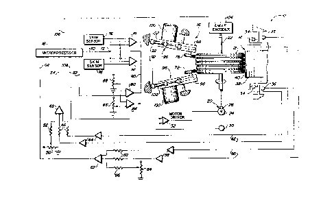
Figure 1 is a schematic illustration of a tire uniformity
machine for detecting, measuring and reducing force variations
in a pneumatic tire.
Figure 2 is a detailed electrical diagram illustrating one
10. of the summer amplifiers shown in Figure 1.
ETAILE~ DESCRIPTION OF THE INVENTIQ~I
In Figure 1 there is shown by schematic representation a
tire uniformity machine 10 which operates to reduce radial and
lateral force variations in a pneumatic tire 12 in a faster and
15. more efficient manner than was previously possible. The tire
uniformity machine 10 includes a detection assembly 14 to
sense and measure force variations In a tire, a rubber removal
assembly 16 to remove rubber from the tire 12, a
microprocessor 18 to process signals received from the
2Q. detection assembly and a motor 20 for rotating the pneumatic
- tire at various speeds.
The motor 20 includes a rim upon which the tire is
mountsd. The rim is carried on a spindle 22 turned by a
variable speed rotary drive means 24. The drive means 24 is
25. capable of rotating the tire at various speeds as between about
1 and about 200 rpm. The speed during the grinding phase of
the opsration is determined by the type of tire being processed
but seldom exceeds 15 rpm. The speed during the sensing phase
1 32504~
12
of the operation has heretofore been a standard 60 rpm but, in
accordance with the present invention is signifieantly higher,
100 rpm in accordance with the preferred embodiment as
disclosed herein for accellerating the tire uniformity
05. correction process. The drive means 24 has the capacity to
rapidly change from the grind speed to the nongrind speed and
from the nongrind speed to the grind speed in less than one
second and more preferably in less than about l/4 seeond.
The grind speed and nongrind speed ean be aehieved by a
1~. drive means such as an AC motor with suitable gearing and
clutching or can be aehieved with a DC motor. It has been
found, however, that a low inertia DG motor and a 10:1 gear
reducer 28 can achieve the various rotating speeds as well as
the speed changes. Sueh a low inertia DC motor has a rating of
15. about 5 horsepower and ineludes a motor shaft to whieh is
attaehed a taehome~er 30 for providing feedbaek to a motor
driver 32 for eontrolling the motor speed. The preeise speed
control of the low inertia DC motor is faeilitated by the motor
driver 32 and, more preferably, by a single-phase adjustable
20. spe~d regenerative DC motor driver. There are a number of
servo meehanism motion eontrol motors and drives whieh are
available to the de~igner to perform this funetion.
The means 14 to deteet and measure radial foree
variations in the tire ineludes pairs of load eells 34 and 36 and
25. a loadwheel 38. The loadwheel has a eylindrieal surfaee 40
upon which the tire 12 rotates for imparting rotation to the
loadwheel. The loadwheel is adapted for free rotation about a
non-rotating axle spaeed from, but parallel with, the axis of
' ' : ~ ' .: ' . ' ' - ' . . ' . '.''.. : ' ' " ' . .: ' ', ' ' ', ' : . ,
1 325048
1 3
rotation of the tire. The axle upon which the loadwheel 38
rotates is adjustably mounted so that it may be positioned
closer to, or farther from, the axis of rotation of the tire. In
this manner, a predetermined deflecting load may be set up
05. against the tire 12 by the surface 40 of the loadwheel 38.
Operatively coupled to the loadwheel 38 are two pairs of
load cells 34 and 36 whieh eontain sensors sueh as strain
gauges for measuring the forces exerted on the loadwheel by
the rotating tire in both the radial and lateral direetions. The
10. Ioad cells 34 convert the radial force variation measurements
to electrical signals sueh as voltage level signals which are
fed via lines 42 through instrumantal amplifiers 44 and series
resistors 46 before being eombined in a summer amplifier 48.
In addition to the inputs from lines 42, the summer amplifier
15. receives a predetermined load signal command from a load
potentiometer 50 whieh is passed through a resistor 52. The
output from the summer amplifier 48 passes through line 54
into the microproeessor 18.
Also operatively eoupled to the loadwheel 38 are the
20. second pair of load eells 36 whieh contain sensors such as
strain gauges for measuring forces exerted on the loadwheel by
the rotating tire in the lateral direction. In a manner similar
to load eells 36, the load cells 34 convert the lateral force
variation measurernents to voltage level electrical signals
25. which are fed by lines 56 through amplifiers 58 and series
resistors 60 and are then combined in the summer amplifier 62.
The summer amplifier 62 also reeeives a predetermined load
signal command from a load potentiometer 64 whieh is fed
. ~ . ,: . .. .. , . . - . . . .
': ,: ,:. , . '., '.. . ' ' i,'. .', ' ' _ .'' ' '', :, " ' ' ' ' . , .
1 325~8 ~:
14
through a resistor 66. The output from the summer amplifier
62 passes through line 68 into the microprocessor 18. In this
manner, the microprocessor 18 receives variable inputs from
both the radial load cells 34 and lateral load cells 36 in
05. addition to the input from the angle encoder as will be
described later.
During the testing phase, the microproaessor 18
receives, processes and interprets the radial and lateral force
variation signal, and stores the interpreted signals in its
10. memory. Later, during the grinding phase, the microprocessor
18 produces a control signal for controlling the grinding of the
tire as a function of the stored radial and lateral force
variation signals. The microprocessor will be described in
greater detail hereinafter.
15 . The output of the microprocessor 1 8 includes a control
signal on line 70 which is sent to a nodal point 72. There the
signal is divided into two control signals. The two control
signals are fed into servo amplifièrs 74 wherein they are each
summed with signals from skim sensors 76 which measure and
20. control the nongrinding distance between the grinding wheels
78 and the shoulders of the tire 12.
The skim sensors are simpiy conventional paddles which
push against the tire during the sensing phase. When the tire
gets larger in diameter due to excessive force variations, the
25. tire pushes out the adjacent paddle which, in turn, generates a
signal to servo amplifiers 74 to move the grinders to positions
toward or away fom the tire being ground. The paddles are
located on the shoulders of the tire immediately in front of the
''':
. - , ; . - - ~ . , . .. ~ .. ; . . . -
1 325048
1 5
grinders.
A signal from the microprocessor 18 also passes through
line 82 to a grind classifier 80 and to a scrap classifier 84. A
scrap limit potentiometer 86 establishes a preselected value
05. for a maximum limit detection so that if the microprocessor
signal exceeds the preselected value, the tire will be
considered non-correctable, no grinding will occur and the tire
will be dismounted from the tire uniformity machine 10. If the
tire is not non-correctable, the grind classifier 80 will
10. compare the signal with a voltage from a grind limit
potentiometer 88 to determine whether additional grinding is
required. If the tire is at or below the minimum level and no
additional grinding is required, the signal of line 90 is summed
in the servo amplifiers 74 effecting retraction of the grinding
15. wheels 78. If the tire is between the upper and lower limits,
the signal summed in the servo amplifiers 74 is converted to a
hydraulic control signal. Such hydraulic control signal is
passed through lines 92 to the rubber removing means 16 which
is comprised of the two grinders 96.
20. The two grinders 96 include frames 98 which support
electric motors 100, hydraulic systems 102 and grinding
wheels 78. The frames 98 are pivotably mounted on the fixed
portions of the rnachine 10 with suitable devices such as pins
to ailow for each grinder 96 to pivot toward or away from the
25. shouldsr of the tire 10.
The microprocessor 18 also has an input signal from the
angla encoder 104 along a line 106. The angle encoder is
suitably attached ~o the spindle 22 for determining the angular
'- . ' '
,:.
''', ~,
1 325048
16
position of the tire. The signal from the angle encoder 104 to
the microprocessor 18 coordinates the location of the grinding
of the tire taking into account the angle difference between the
loadwheel 38 and the grinders 96~ The angle encoder also
05. adjusts for sufficient lead in time between the tire and the
grinders when required.
The method of the present invention involves rotating the
pneumatic tires at a nongrind speed and a grind speed wherein
operations such as loading, warmup and testing can be done as
10. quickly as possible at a nongrind speed of about 100 rpm, well
above the industry standard of 60 rpm. Thereafter the rotating
tire is slowed to a grind speed in less than l/4 second. The
actual rpm for grind speed is determinad based on the design of
the tire and on desired productivity and appearance constraints
15 for the tire.
The tire 12 is initially chucked up on the rim and inflated
whereafter the tire is rotated at a selected speed, preferably
at about 100 rpm. The loadwheel 38 is advanced against the
tire so that the tire is loaded to a predetermined load within
20. about 2 revolutions. Thereafter the tire is rotated for
additional revolutions under the predetermined load.
The tire 12 is then tested for radial and lateral force
variations. The magnitude of the force variations is detected
and measurad, preferably within a single revolution. Thereafter
25. the microprocessor will compare the magnitude of force
variations with a predetermined magnitude. The microprocessor
will then decide whether a grind is necessary. If a grind is
r6quired, the microprocessor will signal the motor driver 32 to
1 325048
1 7
reduce the rotational speed of the tire. A signal will also be
sent to the rubber removal means 16 to remove selected
amounts of rubber from selected regions of the tire in a
programmed manner.
05 . The electrical signals provided to the microprocessor 1 8
include data samples for each test revolution of the tire with
each sample representing a separate measurement of the force
variation at the different angles. A measurement ot the force
variation at each degree increment of the tire is thereby
10. specifically referenced to an angle location by the angle
encoder 104. The above described samples psr revolution are
processed and fed into the microprocessor where a Fourier
analysis calculation of a cyclic function is performed. The
harmonic high point of force is calculated therefrom. The
15. composite peak to peak force is also caleulated by comparison
of the sequential force measurements obtained during the
single test revolution.
The mieroproeessor 18 eompares the harmonie peak to
peak and the composite peak to peak values ealeulated from a
20. test cycle with a predetermined aeceptable grind range If the
radial harmonie peak to peak and the radial eomposite peak to
peak are less than the aceeptable ran~e, no correction is
needed. The tire is satisfactory and ready for use, and it is
removed frem the maehine 10. If either or both the harmonie
25. peak to peak and eomposite peak to peak exeeed the acceptable
range as determined by the scrap classifier 84 and the scrap
limit potentiometer 86, the tire has force variations that
cannot be corrected by grinding to bring either the radial
1 32504~ :
1 8
harmonic peak to peak or the radial composite peak to peak
force variations within the predetermined acceptable range. If
tha radial harmonic peak to peak force variation and radial
composite peak to peak force variation fall within the
05. acceptable grindable range of either or both without either
exc~eding the second limit, the grinding procedure is performed
to reduce the radial force variations.
The microprocessor 18 also utilizes a grinder
displacement angle which is the difference in degrees between
10. the loadwheel 38 and the location of the grinders 96 and 98. In
addition to the grinder displacement angle, a fixed number of
milliseconds prior to the grind is set which allows for the
reduction of the speed of the rotating tire while the
microprocessor receives the signal along line 106 from the
15. angle encoder 104. Also, a signal is sent from the
microprocessor 18 along line 108 to the motor driver 32 which,
in turn, will slow the motor 24 down to allow for the grinder to
be located at the leading edge of the desired grind patch at the
time the spindle speed is reduced to the desired grind speed.
20. A grind signal is sent from the microprocessor 18 along
the line 70 to a nodal point 72 wherein the signal is divided
into two signals. Each of the signals passes through a servo
amplifier 74 wherein the signal is converted to a hydraulic
signal which is passed through lines 92 to bring the two
25. grinding wheels 78 into grinding engagement with the leading
edge of ths grind patch of the tire after the tire has slowed
dewn to a predetermined speed. In a first mode of grinding,
which may be termed ~composite grinding", the grind patch
1 325048 ~:
1 9
consists of all parts of the tire corresponding to angles of the
tire which contain force variation values greater than a
constant value of a calculated limit which is a praportionate
part of the difference between the measured peak value of
05. force variation and a discrete force level which is generally
termed the "suppressed limit." The tire is ground when the
value of the measured tire force variation as referenced to its
soft spot is greater than the suppresssed limit.
The microprocessor 18 is programmed to determine a
10. grind patch which corresponds to the minimum angle of tire
rotation during grind. One means used to attain the minimum
angle of rotation is to start at the calculated radial soft spot
and compare sequential force variations with the suppressed
limit as measured both in a clockwise and a counterclockwise
15. direction from the soft spot. The total angle subtended before
exceeding the suppressed limit in both directions is termed the
no-grind portion of the tire. The remaining angu!ar portion of
the tire correspond to the desired grind patch which is
normally 180 degrees or less. Generally, the grind patch is
20. Ionger as greater force removal is required. When the peak to
peak force only exceeds the suppressed limit by 5 pounds, the
grind patch may be as small as 20 degrees.
Upon complstion of grinding the grind patchi the grinder
is disengaged from the tire. The microprocessor then sends a
25. signal to the motor driver 32 to speed up the rotating tire to
the nongrind speed to about 100 rpm whereupon the tire is again
tested for force variations. A determination as to any further
grinding is again made. If no further grinding is required, the
. .
1 325048
rotating tire is stopped and the tire is ejeeted from the tire
uniformity machine 10.
In an alternate rnethod of grinding, generally termed
~harmonic grinding," the grind output for harmonie correetion is
0~. constructed in the microprocessor and is the real time
difference between the ~synthesized harmonic function" and a
"harmonic suppressed limit." The sythesized harmonic function
is calculated from the magnitude of the harmonie peak to peak
force and the phase of the harmonic foree as ealeulated by the
10. Fourier methods referenced above. The grind output determines
a grind patch which is of equal lengths on both sides of the
harmonic high point. The grind patch is normally less than or
equal to 180 degrees.
Prior art tire uniformity machines traditionally utilize
15. 60 rpm, the industry standard speed, when sensing foree
variations in tires. While sueh referenee speed eould,
theoretieally, be inereased by various meehanieal or eleetrieal
teehniques, the present tire uniformity maehine employs analog
electrical signals at frequeneies ,higher than the industry
20. standard of 60 eycles per minute as the detected signals from
the load cells. Such deteeted signals are sent to improved
summer amplifiers 48 and 62 in order to ereate a filtered, high
frequency signal for being fed to the microproeessor. This has
proven to be the prefsrred technique for inereasing the
25. rotational speed of the tire during testing and thereby speeding
up the entire uniformity eorreetion proeess. Exeept for the
details of the increased speed, the summer amplifiers and the
el0ctrical components to effeet sueh inereased speed, the
1 325O48 21 ;
~bove described apparatus is essentially the same as ~;
~hat descri~ed in Canadian Patent Application Serial
Number 521,~69, filed October 31, 1986, C.L. Rogers, - .
Jr., entitled Tire Uniformlty Correction~ as assigned
05. to the same assignee as the instant invention of which
this application is an improvement. . ; .
The two summer amplifiers 48 and 62 are preferably of ::
identical construction. As a result, only one of such summer -
amplifiers will be described. Each of the summer an p!ifiers
lO. includes a pair of series amplifiers 112 and 114. The first -
series amplifier 112 is an operational amplifier which receives
its signal at its inverting input. Series resistors 116 and 118, :
having values of 50,000 and 19,100 ohms, respectively, are
located in series with the inverting input of the first series -`
15- amplifier. Coupléd with the output of the first series
.
amplifier, and feeding back to its negative gate, is a capacitor
120 having a value of 0.1 microfarads. Also coupled with the
output of the first series amplifier is resistor 122. This
resistor has a valus of 50,000 ohms and feeds back to a node
20- between the series resistors 116 and 118. The non-inverting
input of series amplifier 112 is grounded through resistor 124
having a value of 43,000 ohms. The input to the invertlng input
has further connections between the series resistors 116 and
118 which is grounded through a capacitor 126 having a value
25- of 0.1 microfarads. The output of the first series amplifier
1 12 is fed through a series resistor 128 of 107,000 ohms to
the second series amplifier 114.
The second series amplifier 114 is a buffer amplifier.
Its input from the first series amplifier 112 is to its
1 3250~8
22
non-inverting input. The output from the second series
amplifier is fed back to its inverting input through a resistor
132 having a value of 110,000 ohms. The non-inverting input of
the second series amplifier is grounded through capacitor 134
05. having a value of 0.1 microfarads.
The first two series amplifiers, along with their
associated resistors and capacitors as described above,
constitute a three corner filter network 138, the equivalent of
a third order Butterworth filter. Resistor 116 and capacitor
1 0. 126 constitute one corner filter. Resistor 118 and capacitor
120 constitute a second corner filter; and resistor 128 and
capacitor 134 constitute a third corner filter.
Thesa two series amplifiers with their associated
resistors and capacitors constitute networks for filtering and
15. correcting the higher frequency electrical signals received
from the load cells. Prior to the output of the series
amplifiers being fed to the microprocessor, the output of the
second series amplifier is fed to zero suppression network
circuitry 140 wherein a DC component of about 2.00 volts is
20. removed so that variations in the detected and processed
signals will vary about a zero volt reference potential. Lastly
within tha summer amplifier, is gain adjustment circuitry 142
including a buffer amplifier. Consequently, the outputs of the
summer amplifiers 48 and 62, as shown schematically in Figure
25. 1, are really the output of the buffer amplifier having been fed
through the two series amplifiers of the filter network
circuitry and the zero suppression network.
As the frequency to a capacitor increases, the
.. . .. . . .. ... ... .. . ... . .. . . . . . .. .... . .
1 325048
23
capacitor's reactance decreases proportionately. Because of
this relationship, the values of capacitors 120, 126 and 134 of
the summer amplifiers, in the preferred embodiment of the
present invention, are decreased to 0.6 times the values they
- ~5. would have been if the present machine were to be operated at
the conventional industry standard frequency of 60 cpm and the
conventional industry standard rotational speed of 60 rpm. In
other words, by converting a prior art, conventional slower tire
uniformity machine with its 60 cpm frequency and its 60 rpm
10. tire rotational speed to the faster machine with its 100 cpm
frequency and its 100 rpm tire rotational speed, 1.67 times its
original spsed, the capacitor values in the summer amplifiers
are decreased to the reciprocal of 1.67 or 0.6. It should be
appreciated, however, that the values of the various electrical
15. components as disclosed herein are for describing the preferred
embodiment of the invention and are provided fcr illustrative
purposes only. As can be understood, the present invention
could be readily practiced within a wide range cf opera~ing
parameters. It could also be practiced by a wide ranse of means
20. including digital filterin~ methods as attainable with suitable
algorithms and encoding in a microprocessor or
micro-computer.
The electrical input to filtering summer amplifiers in
prior art tire uniformity machines running at the industry
25. standard speed of revolution, 60 rpm, are signals generated
with industry standard fundamental frequencies, 60 cpm. Such
prior art signals are not modified in frequency content as are
the signals generated when such machines run at higher speeds
.
1 3250~8
24
of rotation as disclosed herein. Such signal modification in
signal content is directly proportional to the increased speed
of revolution. When the input signals to the summer amplifiers
are filtered, whether in the prior art devices or in accordance
05. with the present invention, the filtering is effected in
accordance with the filter characteristics of the summer
amplifier. In the present invention, the summer amplifier
modifies by either modification or attenuation each individual
harmonic of the received frequency modified signal from the
10. first harmonic up to and including the sixteenth harmonic. All
subsequent, higher harmonics are filtered out as being
unnecessary for a proper interpretation of force variations for
the subsequent corrective grinding. In the present filtering
network, however, the summer amplifier must have its
15. component elements selected so as to attenuate
proportionately each harmonic o~ the received signal by a
factor identical with that factor which corresponds to the
attenuation of each harmonie as contained in the original
summer amplifier designed for 60 rpm operation of the spindle.
2~. Thu~, the output to the microprocessor for interpretation,
storaye and subsequent grinding will be the same as if the load
sensor signals had been generated and processed at the
conventional industry standard speeds. ~
Between the output of the lateral summer amplifier 62
25. and tha microprocessor 18, there could be provided additional
circuitry to detect for conicity of the tire being tested. It is
preferred, howaver, to feed the output of the laterai summer
amplifier 62 directly to the microprocessor wherein
~., .',
.
: . - - -, - -. ,, .. . - . - ., - , . . , - . . . . .
': ' - .-: .:. :' '':-. .'..., ' ::-: .... ' ::: -': ..: ' '', ,.. .: .: ': . ': ' : '- '- :
1 325048 ~ :
programmed software is employed to interrogate the output of
the lateral summer amplifier for determinations of conicity.
Two signals are connected to the microprocessor. One is the
lateral composite and the second is the radial composite signal.
05. These signals are composite signals which vary as a function of
the force variations in the tire and are cyclic, once per tire
revoiution. The fundamental component of each signal is the
radial first harmonic signal and the lateral first harmonic
signal. These are determined in the microprocessor from the
10. composite signals. This is accomplished by a special software
digital process within the microprocessor through a Fourier
analyses. The microprocessor also takes the lateral composite
signal and integrates its value when measured during tire
rotation in the clockwise direction to determine its DC
15. component. The tire is then rotated in the opposite or
counterclockwise direction. The microprocessor then
de~ermine the DC component of the lateral component in the
opposite direction. These two DC components and subtracted,
one from the other, to determine the difference which is
20. divided by two. This value is the factor representing the
conicity of the tire. It should be understood that the conicity
determination may or may not be utilized in association with
the tirs uniformity machine of the present invention and has no
bearing on the overall, efficient, high speed operation of the
25. machine as described herein.
The present disclosure includes that information
contained in the appended claims as well as that in the
foregoing description. Although the invention has been
1 325048
26
described in its preferred form or embodiment with a certain
degree of particularity, it is ùnderstood that the present
disclosure of the preferred form has been made only by way of
example and that numerous changes in the details of
05. construction, fabrication and use, including the combination
and arrangement of parts and method steps, may be resorted to
without departing from the spirit and scope of the invention. ` ::
~ .
.'..::.:.
: ~.
;''""'
. -:~..' :.
,.~.:',.,.'-.