Note : Les descriptions sont présentées dans la langue officielle dans laquelle elles ont été soumises.
t~`. 13257~ 0
-- 1 --
The present invention, in one embodiment, relates
to seals of the type which may be used for closing
flexible containers such as mail bags. This invention
also relates, in another embodiment, to seals which may
5 be used for locking other types of containers such as
tote boxes for jewelry, zipper openings in flexible bags
such as are used for carrying payrolls, cash drawers in
bank vaults, etc.
More particularly, one embodiment of this invention
relates to a seal which can close the open mouth or neck
of a bag, and in one particularly preferred embodiment,
provides means for attachment of identification or
destination labels to the seal itself.
In another embodiment, a seal is provided which can
be used for locking other types of containers such as
those mentioned above and in which the seal has an
adjustable feature.
Typical of seals used for closing bags are
illustrated in U.S. 3,371,949 (March 5, 1968); 2,77~,909
2Q ~December 4, 1956); 2,669,476 (February 16, 1954);
2,983,539 (May 9, 1961). All of these seals, however,
re~uire the use of a plurality of separate parts for
closing the bag. Thus, the bag encircling member is
usually in the form of a rope or cord; a separate piece
for gripping the neck of the bag is provid~d; and still
further a deformable sealing element, usually of metal,
holds the rope or cord about the neck of the bag. In
addition, it is necessary to have a separate tool for
deformation of the sealing element once the structure
has been placed around a bag to be closed.
- . . .
.
. .
- . . .
132~710
-- 2
The prior art also discloses various types of seals
suitable for closing other types of containers. For
example, UOS. Patent 3,290,080 (December 6, 1966) is a
"padlock" type seal in which a shaft is inserted into
the body of the seal. A series of barbs provided on the
shaft engage with a cooperating configuration inside the
body of the seal.
U.S. Patent 4,059,300 (November 22, 1977) employs a
latch which is inserted into a housing for engagement
with fingers therein.
U.S. Patent 4,~29,031 (October 21, 1980) and U.S.
Patent 3,46~,077 (September 9, 1969) also have a similar
structure where a latch engages fingers inside a
housing.
These types of seals are generally used for locking
truck containers, freight cars, etc.
British Application 2,115,35~ published September
7, 1983, illustrates a type of security seal for locking
a zip fastener in postal envelopes.
Typical of seals currently used for locking, e.g.,
cash drawers, are padlock type seals ("Chicago" locks).
None of the above prior art seals, however, provide
any adjustability; in other words, the seals are only in
a locked state at a certain point when the latch has
been appropriately positioned to mate with its
cooperating component. In addition, some types of
padlock seals currently in use require a key to open the
lock. This obviously causes problems in that keys are
easily lost; in addition, these types of locks are very
e~pensive.
.
", . ,
132~7~
It is a feature of one embodiment of the present
invention to provide a seal for flexible containers such as
bags and which provides both a gripping and locking
function in a one-piece structure.
It is a feature of another embodiment of the
present invention to provide a seal which provides
adjustability, which does not require the use of a key to
open the same, and which is relatively inexpensive to
manufacture relative to a metal padlock type of seal.
In accordance with an embodiment of the present
invention there is provided a one-piece gripping and
locking seal. The seal comprises: a socket member having
first and second open ends communicating with a passageway
through the socket and at least one locking means in the
socket member, the locking means comprising at least two
deflectable fingers extending in opposition from opposite
walls of the passageway into the passageway; and a latch
member having opposed surfaces. The latch member comprises
a first flexible extension member integral with the socket
member and extending laterally therefrom; a second
extension member for insertion into the first end of the
sockat member and extending from the first flexible
extension member and being integrally connected thereto,
the second extension member having opposed surfaces; and a
plurality of engagement members extending from each surface
of the second extension member and normal thereto, for
progressive engagement by the deflectable fingers. Each
engagement member has a flat engagement surface acing
towards the socket member, whereby upon insertion of the
second extension member into the first end of the socket
member, the deflectable fingers engage the engagement
: :
. ~
~' 132~710
-- 4 --
members of the second extension member and the latch member
can thereafter only be pulled towards the second end. The
socket member is further provided with a plurality of
deflectors extending into the passageway, the plurality of
deflectors adapted to deflect any tool which may be used in
trying to disengage the deflectable fingers from the
engagement members.
In accordance with another embodiment of the
present invention there is provided a one piece gripping
and locking seal for closure of flexible containers. The
seal comprising: a socket member having first and second
open ends communicating with a passageway through the
socket and at least one locking means in the socket member,
the locking means comprising at lest two deflectable
fingers extending in opposition from opposite walls of the
passageway into the passageway; and a latch member having
opposed surfaces. The latch member includes a first
flexible extension member integral with the socket member
and extending laterally therefrom and having container
gripping and engaging means on one of the opposed surfaces
adapted to encircle and grip a neck of a flexible
container; a second extension member for inser$ion into the
first end of the socket member, extending from the first
flexible ex~ension member and being integrally connected
thereto, the second extension member having opposed
surfaces; and a plurality of engagement members extending
from each surface of the second extension member and normal
thereto, for progressive engagement by the deflectable
fingers. Each engagement member has a flat engagement
surface facing towards the socket member, whereby upon
insertion of the second extension member into
,~
.
1 3 2 5 7 1 0
the first end of the socket member, the deflectable Eingers
engage the engagement members of the second extension
member and the latch member can thereafter only be pulled
towards the second end. The socket member further includes
a plurality of deflectors extending into the passageway,
the plurality of deflectors adapted to deflect any tool
which may be used in trying to disengage the fingers from
the engagement members.
lQ In accordance with a further embodiment of the
present invention there is provided a seal for providing a
security closure. The seal comprising: a socket member
having first and second open ends communicating with a
passageway through the socket member, and at least one
locking means within the passageway spaced from both the
first and second open ends, the locking means comprising at
least two deflectable fingers extending in opposition from
opposite walls of the passageway into the passageway: and
a latch member. The latch member includes an encircling
member in the form of a first flexibla extension member
integral with the socket member and extending laterally
therefrom, the encircling member having a center portion
and a pair of outer edge portions, the center portion being
thicker than the outer edge portions; and a second
extension member extending from the first flexible
extension member and being integrally attached thereto, the
second extension member having opposed surfaces.
plurality of engagement members extend from each surface of
the second extension member and are normal thereto, for
progressive engagement by the deflectable fingers. Each
engagement member has a flat engagement surface facing
towards the socket member,
. .
~ 132571~
-- 6 --
whereby when the second extension member is inserted into
the first end of the socket member, the engagement member
is engaged by the locking means. The socket member further
includes a plurality of deflectors extending into the
passageway, the plurality of deflectors adapted to deflect
any tool which may be used in trying to disengage the
deflectable fingers from the engagement members.
In accordance with a still further embodiment of
the present invention there is provided a seal for closure
of the mouth of flexible containers comprising: a socket
member having first and second open ends communicating with
a passageway through the socket member, and at least one
locking means comprising at least two deflectable fingers
extending in opposition from opposite walls of the
passageway into the passageway; and a latch member integral
with the socket member. The latch member includes a first
flexible extension member extending laterally from the
socket member, having container gripping and engaging
members on a surface, adapted to encircle and grip a neck
of a flexible container; and a second flexible extension
member having opposed surfaces for insertion into the first
end of the socket member and extension therethrough, the
second extension member extending from the first extension
member and having a plurality of engagement members spaced
apart along each of the opposed surfaces for sequential
engagement hy the deflectable fingers. Each of the
engagement members includes a shoulder defined by a tapered
recess in the opposed surfaces and having a flat engagement
surface facing toward the socket member, whereby when the
second extension member is inserted into the first end of
L~
. ' . . ~ ..................... ,
. . . . . . - .
. . , , ~, ,
~ 132~710
- 6a -
the socket member, progressive engagement of the engagement
members enables cinching of the seal around a neck of a
container. A plurality of deflectors are provided in the
socket member, the deflectors extending into the
passageway, and adapted to deflect any tool which may be
used in trying to disengage the deflectable fingers from
the engagement members .
In accordance with yet another embodiment of the
present invention there is provided a seal for providing a
security closure, comprising: a ~ocket member having first
and second open ends communicating with a passageway
through the socket member, and at least one locking means
within the passageway spaced from both the first and second
open ends, the locking means comprising at least two
deflectable fingers extending in opposition from opposite
wall~ of the passageway into the passageway; a latch member
integral with the socket member and comprising a first
flexible extension member extending laterally from the
2n socket member, and a second flexible extension member for
insertion into the first end of the socket member, the
second extension member extending from the first extension
member and having opposed surfaces, at least one engagement
member on each of the opposed surfaces for engagement by
the deflectable fingers, each the engagement member
comprising a shoulder defined by a tapered recess in the
vpposed surfaces and having a flat engagement surface
facing toward the socket member, whereby when the second
extension member is inserted into the first end of the
socket member, engagement occurs between the locking means
and the engagement member. The socket member further
includes a plurality of deflectors
.
' ' ~: ' ~ '' :
. .
1 3 2 ~ 7 1 0
- 6b -
extending into the passageway, the plurality of deflectors
adapted to deflect any tool which may be used in trying to
disengage the deflectable finyers from the engagement
members.
In a preferred form of the flexible container
seal, the first extension member includes gripping and
engaging means which take the form of a plurality of
spaced-apart projections extending from the first flexible
extension member. Generally, it is desirable to provide
such projections with relatively pointed ends so as to
enable a good gripping action around tha neck of a bag or
flexible container. Also, the first flexible extension
member may be of a thicker construction so that a thicker
central strip is provided on the surface opposed to that
from which the projections extend so as to improve the
strength thareof. As such, a central strip of a greater
thickness may be provided along the length of the first
flexible extension member.
In the flexible contain~r seal, it is also
preferred that a plurality of socket engaging members be
provided on the second extension member so that the seal is
adjustable to different sizes about the neck of a flexible
container. Thus, upon insertion into tha socket member,
the socket engaging members progressively engage the
cooperating loc~ing means to thereby permit the required
adjustment.
In a preferred form of the seals of the
invention, the length of the first extPnsion member and the
socket member are such that upon insertion of the second
extension member into the first end of the socket member,
the last one of the socket engaging members to enter the
-.~
, : ,-,' ,
~ 132~ 0
- 6c -
socket member cannot exit the second end of the socket
member.
In preferred embodiments of the seal, a preferred
feature is that of the provision of a third flexible
extension member extending from the second extension
member. This extension member is integrally attached to
the second extension member and is useful in guiding the
second extension member into the socket and to pull it
10therethrough. In a particularly preferred form, the third
extension member takes the form of label retaining means.
The label retaining means of the third flexible
extension member preferably takes the form of a strap
member having an aperture at one end and an enlarged head
at the other end. In use, the enlarged head is moved
towards the aperture at the other end, creating a circular
outline for retaining a label attached to the seal. The
enlarged head has shoulders which seat on the outer
periphery of the aperture, thus holding th~ head in the
20aperture. Small sloks may be provided at opposed sides of
the aperture so as to aid in insertion of the enlarged head
therethrough.
The seals can be formed of any suitable plastic
material such as polyolefins, e.g. polyethylene,
polypropylene, copolymers of these materials, and the like.
While the first extension member requires
flexibility, it may also be possible that the second and
third extension members be formed of a relatively more
rigid material, although for ease of construction and use,
30it is preferred that the whole seal be formed of the same
material.
1:~
, ~ ~
:~ . ,, : :, . :
: , ~ .:
~3~7~
-- 7
It will be appreciated that the seal can be
appropriately sized for the particular application. Any
number of socket engaging members can be provided
depending on the desired degree of versatility and
adjustability. In a preferred form, from 3 to 15 socket
engaging members are provided to give a relatively large
degree of adjustability; however, the seal would also be
adjustable with 2 socket engaging members and in some
cases, it may be desired to have more than 15 socket
engaging members.
The lengths of the various sections of the latch
member will also depend on the particular application.
In one form, the length of the first extension member is
such that upon insertion of the second extension member
into the socket, the last one of the socket en~aging
members to enter the socket cannot exit the second end
thereof.
Having thus generally described the invention,
reference will now be made to the accompanying drawings,
illustrated preferred embodiments of the invention, and
in which:
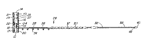
FIGURE 1 is a side e]evational view of a seal
according to one embodiment of the present invention;
FIGURE 2 is a bottom view of a seal;
FIGURE 3 is a side elevational view of a seal in a
locked position;
FIGURE 4 is a view similar to Figure 3 with parts
broken away.
FIGURES 5 and 6 are perspective views of another
3~ embodiment of the present invention; and
', , , :'~ '
,
`` 132~71~
-- 8
FIGURE 7 illustrates a socke-t member in accordance
with Figures 5 and 60
In greater detail, a one-piece seal for closing
flexible containers according to an embodiment of the
present invention comprises a socket 10 of a cylindrical
or tubular configuration. Socket 10 has opposed open
ends 12 and 14 communicating with a passage 16 extending
through socket 10. As illustrated, open end 12 of
socket 10 has a smaller opening than opposed open end
14. Thus opposed inner walls 18 and 20 form a
substantially rectangularly shaped opening of reduced
size in end 12 of socket 10. Located within socket 10,
and extending from walls 18 and 20 is a pair of opposed,
spaced apart7 resilient fingers 22 and 24. As seen from
Figure 1, fingers 22 and 24 extend toward open end 14
and are directed inwardly somewhat leaving a space
between the fingers of reduced size relative to the size
of the remainder of passageway 16. Fingers 22 and 24
are relatively resilient in that they can be urged
further apart, however, upon release of any tension
thereon, fingers 22 and 24 flex back to their original
position.
Also provided within passageway 16 are ribs 17 and
19 on opposed sides in staggered relationship to each
other. Towards end 14, a pair of deflectors 21, 23 and
25, 27 are also provided on opposed sides within socket
10 .
The seal of the present invention further comprises
a latch member indicated generally by reference numeral
:
: ., . . . . , .
~, ' , - ~ : '
: . :: . . ,
~ 132~71~
26. Latch member comprises an extension extending
laterally from socket member lO and integrally connected
thereto at a point spaced from end 12. In the
illustrated embodiment, latch member 26 comprises three
sections 28, 30 and 32. Section 28 is the gripping
portion oE the latch member and comprises a relatively
thin, flat and planar extension of the same or similar
width as socket member lO tFigure 2). As shown in
Figures l and 2, gripping portion 28 has a plurality of
longitudinally spaced apart projections 34 which act as
gripping means, as discussed hereinafter in greater
detail. It will be noted from Figure l that gripping
section 2~ may have a thickened area 36 along the length
of projections 34 on the surface opposed to the
projections 34 to provide greater strength to this
portion. There is thus a thickened central strip 36
with the outer side edges oE the gripping section 28
being of a thinner nature to provide ease of flexibility
and aid in forming itself around the neck of a bag.
~0 A small slot 35 adjacent the point where latch
member 26 adjoins socket member lO is provided as a
point of weakness where the seal can be cut or bent and
broken off when it is desired to remove the seal from a
containerO
Section 30 of latch member 26 is a continuation of
the gripping portion 28 and comprises a "Christmas-tree"
configuration having a plurality of shoulders adapted
for cooperation with fingers 22 and 24 of socket member
lO. Thus, section 30 comprises a socket engaging
3Q section having a plurality of tapering sections forming
shoulders 37 spaced along the length of section 30~
: ~' ' ' ' ''' "''` '
.
132~710
-- 10 --
Secticn 32 is a strap-like member extending from
soc~et engaging section 30, and has a plu~ality of
spaced apart ridges 38, an enlarged head 40 and an
aperture 42. Ridges 38 provide for easy gripping of the
seal. Enlarged head 40 is adapted for insertion into
aperture 42. Aperture 42 is of a size so that enlarged
head 40 can be pushed therethrough; in this respect,
slots 44 and 46 on either side of aperture 42 aid in
permitting passage of enlarged head 40 through aperture
42. Ribs 43 may be provided on the outer edges of
section 32 adjacent aperture 42 to provide
reinforcement. Shoulders 48 of enlar~ed head 40 sit on
the outer perimeter of aperture 42, and thus, the
enlarged head 40 is held in the aperture 42 and cannot
be removed without excess pressure being exerted.
Figures 3 and 4 of the drawings illustrate the seal
in its locked position. Thus, it will be seen that the
gripping portion 28 has been curved down and around with
the latch member 26 being inserted through open end 12
of socket 10. Thus, gripping portion 28 creates a
circular inner configuration adapted for encirclement
of, e.g., the neck of a mail bag. The projections 34
thereby grip the neck of the-bag.
As the latch member 26 is~being pulled through the -
socket member and the portion 32 has passed through the
socket and out through end 14, shoulders 37
progressively engage fingers 22 and 24 inside the
socket, with the fingers flexing further apar-t as the
shoulders 37 pass therebetween. Depending on the size of
3a the neck of the bag to be closed, the latch member 26
C
;, ~, ,: ; . .,
132~71Q
-- 11 --
can be pulled through the socket member until a tight
fit of the gripping portion 28 around the neck of the
bag is achieved. At this point, the fingers 22 and 24
are in engagement with one set of shoulders 37 creating
a locking action; it will be understood that the latch
member cannot be pulled back out of the socket due to
the engagement of the fingers 22 and 24 with shoulders
36; on the other hand, the latch member can be pulled
further into socket whereby a greater tightening of the
gripping portion 28 around the neck of the bag is
provided.
In the locked position, the opening of reduced size
in end 12 of socket 10 is substantially closed off by
the tapering portions of second extension member 30 and
thus, access to within the socket is minimized.
Ribs 17 and 19 with their staggered positioning
permit easy insertion of the latch member into the
socket. Thus, with their staggered relationship, ribs
17 and 19 permit second extension member 30 to move from
side to side in insertion into the socket 10. These
ribs, as well as deflectors 21, 23 and 25, 27 serve also
to deflect any tool which may be used in trying to
disengage the fingers 22 and 24 from shoulders 37.
Once the seal has been locked around the neck of a
bag, the portion 32 may then be curved around and the
enlarged head 40 inserted in the aperture 42. The
portion 32 may be curved around either in a downward
direction relative to Figure 3, or on the other hand,
may be curved upwardly and around. The ridges 38 aid in
: . . ~ . -
:~.
: - ' . .
3257~0
- 12 -
gripping the latch member and the enlarged head inserted
in aperture 42, creates a circular outline. This
circular outline can be used for attachment of, e.g.,
identification labels, destination labels, etc. Thus,
for example, if the seal is being used with mail bags, a
destination label could be attached by virtue of label
retaining section 32. As the enlarged head is somewhat
difficult to remove from the aperture, the label will
not become detached from the seal and mail bag, until
such time as some one purposefully removes the enlarged
head from the aperture. It should also be noted that,
e.g., a label can be detached and a new label attached
to the seal, without the necessity of unlocking the seal
or of tearing the label.
It will be noted that the fingers 22 and 24 are
spaced from ends 12 and 14 and are provided
approximately mid-way in the length of socket 10. This
positioning creates the locking action away from the
ends 12 and 14 so that anyone tampering with the seal
would require a longer tool to attempt to disengage the
fingers. The longer the tool, the more flexible it
would be and therefore, it would be difficult to gain
access to the ~ingers, past the deflectors 21, 23, 25
and 27 from one end or past the ribs 17 and 19 from the
other end.
Turning now to Figures 5 to 7, a seal is
illustrated which can be used in cases where other types
of locking requirements are necessary. The Figure 5 to
- ~32~710
7 embodiment can be used in locking a zippered pouch,
cash drawers, jewelry tote boxes, etc.
Figures 5 to 7 will not be described in detail
herein, apart from those features which differ from the
Figure 1 to 4 embodiment. In Figures 5 to 7, like
reference numerals correspond to like components in the
Figures 1 to 4 embodiment, and accordingly, a detailed
description of these like parts is not included
herewith.
Socket 10' is similar to socket 10. However,
instead of thickened walls 18, 20, socket 10' has a
reduced outer diameter with flat walls 18', 20',
creating the smaller opening at end 12'. Latch member
26' is comprised of first extension 28', second
extension 30' and third extension 32'. First extension
28' is merely a flat extension adapted for insertion
through and encircling of, appropriate means on the
container to be locked. Such means may be for example,
a staple and hasp as conventionally used in containers
adapted for locking with a padlock, means provided on a
zipper fastener, etc.
Figure 5 illustrates extension 28' as a flat strap;
Figure 6 illustrates extension 28' with a thicker
central strip 36' as a strengthening feature.
Second extension 30' has locking shoulders 37'
similar to those of Figure 1.
Third extension 32' acts as a guiding section to
aid in insertion into the socket. ~ripping ridges 38'
,,
; '
. , : '
~ 32~i7~0
- 14 -
are provided to aid in insertion. Section 32' may also
be used for placement of indicia such as numbering or
lettering so that such indicia would be easily readable
once the seal is in use.
End 40' of Figures 5 and 6 are appropriately
configured for insertion into the socket 10'. The seals
of Figures 5-7 are employed in a similar manner to that
of Figure 1, that is, latch 26' is placed through
appropriate clasps or hooks on a container to be locked
and is then inserted into end 12'. As extension member
30' passes through the socket, shoulders 37'
progressively engage fingers 22', 24', until the point
where the desired size has been reached.
Although in both of the illustrated embodiments,
the latch member 26 has been shown as extending
laterally from the socket member 10 at a point spaced
from the end 12, it will be appreciated that the latch
member could extend from the socket at various points
thereon, for example, the latch member 26 could extend
directly from the first end of the socket.
In addition, while the extension members have been
shown having diminishing widths (Figures 1-5), e.g.,
extension member 28 being the widest, with extension
member 30 being narrower, and extension member 32 being
narrower still, it will be appreciated that various
widths or the same widths could be utilized for all of
the members, with the socket member being suitably
configured to accommodate the latch member, such as
illustrated in Figure 6.
'' :
.. - . . ..
~32~71~
- 15 -
In cases where no third extension member or label
retaining means are required, it will be appreciated
that the third extension member could be eliminated.
It will also be appreciated that the features
illustrated in Figures 1 to 4 can be interchanged with
those illustrated in Figures 5 to 7 and vice versa, the
specific features being selected so as to provide the
appropriate ones required for the specific applica~ion.
Although the invention has been described with
reference to the specifics illustrated in the drawings,
it will be appreciated that various modifications and
changes may be made thereto, without departing from the
spirit and scope of the inventionO
,. ~ .':,- : ' '
:, ' ~' `