Note : Les descriptions sont présentées dans la langue officielle dans laquelle elles ont été soumises.
~- ~ 132~7~1
10530-16F/Kll
INFRARED FILTER USING CHOLESTERIC LI~UIDS
BACKGROUND OF THE INVENTION
This invention relates to an optical filter system
and more particularly to a sharp transition, high precision
cholesteric liquid crystal combination filter for blocking
the transmission of spurious, nearly visible infrared emis-
sions in a night vision system.
It is well known that a pilot in an attack
aircraft uses night vision goggles that permit the pilot to
see infrared radiation from targets or other objects outside
the aircraft.
Unfortunately, useful equipment within the
cockpit may emit spurious infrared light at levels sig-
nificant enough to cause problems for the pilot. For
example, displays located in the cockpit area for generating
red colored symbology also emit spurious infrared light at
levels high enough to blind the pilot s night vision goggles
to low level infrared sources o interest. In many cases,
the spurious infrared light has a wavelength that is almost
in the visible region. Thus, it is highly desirable in
night vision applications to provide a simple means for
blocking spurious, nearly visible infrared emissions while
permitting the maximum transmission of visible light at
adjacent wavelengths.
Conventional infrared filters are known which
block the transmission o light at infrared wavelengths.
However9 these filters lack the sharp transmission step
characteristic needed to block transmission of nearly
visible infrared light while also permitting maximum
transmission of all visible light up to the infrared range.
Conventional head-up displays, night vision
systems, and known optical devices do not teach or suggest
any arrangement for achieving such a sharp transition high
precision filter.
I ~
,
-
,~
- . .
~ 32~7~1 ~
64157-2~
~ or example, Jacobs, et al~ U.S. Patent No.
4,679,911, teaches the use of cholesteric liquid cry~tal
materials to sllape the profile of an optical beam, e.g., a
la~er. U.S. Patent No. 4,679,91~ to Afron, et al teaches
5 conver~ion o visible images to infrared ~l~ing liquid
cr~stal light valves. U.S. Patent No. 4,4~3,927 to Bly
de~cribe3 a bandpass filter ~Ising twisted nematic liquid
cry~tal devices havillg different time response6 and opposite
rotary direction llalldedlless. V.S. Patent ~lo. 4,39~,069 to
Kay describes a liquid crystal tuned filter using zero-twist
liquid crystal cells to obtain a narrow band transmis~ion
characteristic. U.S. Patents No. 4,232,948 and 4,416,514,
although pertaining to optical systems, do not teach or
suggest any optical filter system capable of transmitting
light up to an abrupt wavelength.
It is known that cholesteric .liquid crystal
optical filter3 are capable of tran~mitting light at
substantially all wavelength~ while reflecting light over a
~ingle, generally narrow,'wavelength band. ~or example,
U.S. Patent No. 3,679,290 to ~dams et ~l discus3e~ the u~e
of a matched pair of cholesteric liquid cry.stal elements to
form all optical llOtCIl filter. ~he notcll Elltel collslst~ of
one element that reflects right-hand circularly p~o~r-
i7ed light n~ar a qiven wav~length and transmit~ l~ft-h~nd
circularly polarized light, and a second film that reflects
left-hand circularly polarized light wavelength and
transmits right-hand circularly polarized light. The two
elements are arranged in series ~uch that the filter
efEectively transmits all incident light with the exception
of the wavelength band centered around that nominal
wavelength. See al~o, U.S. Patent No. 3,711,181 to Adams et
al.
It is also knowll that the unique optical prop-
ertie3 of chole3teric liquid crystal elements can be ex-
3S ploited to provide a wide variety of narrow band fiiteringfunctions extending over A wide wavelength range from the
near ultraviolet to the far infrared. ~or example, atl
.,~
, . . .
:, .. ,.- : .,:. , .: :.
- . . . : ~ ., . ., .:: .
... . .. ,, .. ~ , , .
~ 132~
3 64157-288
article by Adams, et al entitled "Cholesteric Films as Opt:ieal
F.ilters," Journal of Appliecl Physics, Vol. ~2, No. 10, Septemhe.r
1971, discloses several cholesteric element configurations ~7hich
provi.de a notch filter function.
Although the foregoing Aclams references discuss the
general properties of cholesteric liquid crystal -filters, these
references are largely theoretical in nature and do not teach or
sugyest the use of the discussed cholesteric liquid crystal
filters in sophisticated, practical applications. t~
Moreover, it is known that liquid crystal filters suffer
from a number of limitations. First, it is known that the
performance of eholesteric liquid crystal filters drifts over
temperature. Therefore, if two elements are matched at one
temperature, they may drift apart in performance at another
temperature. Moreover, cholesteric liquid crystal filters have
been previously used in essentially narrow band filtering
applications.
Thus, although the use of cholesteric liquid crystal
filters is known, the use of these filters in high precision,
~O night vision, or in wideband filtering applications is neither
taught nor suggested by the art.
SUMMARY OF THE INVENTION
The invention provides a high precision optical filter
system for use in night vision display applications. In
particular, the invention provides a precision optieal filter for
blocking infrared radiation while transmitting visible light. The
optical filter is mechanically simple and easy to fahricate.
Broadly, the optical filter of the present invention
includes a wideband optical filter having a corner wavelength, and
a cholesteric liquid crystal notch filter with the notch including
the quarter wavelength, thereby forming a high-precision wideband
optical filter. In an implementation of the invention,
.
. ..
- ~ - .
:,: :.
~ 13257~
3c~ 64157-~88
an infrared optical filter is formed, comprising an infrared
filter for blocking transmission of light over a wide infrared
hand, the infrared filter having a nearly visible corner
wavelength, and a cholesteric liquid crystal filter for blocking
transmi.ssion of infrared light in a narrow band, the narrow band
including the corner wavelength.
Optical filter formed according to the present invention
comprise an infrared absorptive filter and a cholesteric li~uid
filter which are used in combination to block transmission of
light at infrared wavelengths while transmitting visible light up
to a precisely defined wavelength. The infrared absorptive filter
blocks infrared light over a wideband beginning at a first nearly
visible corner wavelength. The
., .
- ' - :. ` '` : ' `: :' ,: ::' ` : i, ,
.. .. . .. . .
-~ t 13257~1
4 64157-288
cholesteric liquid crystal filter bloc]cs transmission of infrared
wavelengths in a precise narrow band that incluc1es the nearly
visihle corner wavelength. The cholesteric filter ~an include a
combination of cholesteric and nematic liquid crystal material,
with the amount and nature of the nematic component determining
the wideband for the liquid crystal cholesteric filter and the t
precision of the combination optical filter.
In one embodiment, the liquid crystal filter includes
polymer cholesteric films for maintaining stable performance
characteristics over a wide operating temperature range.
The invention may be fabricated by depositing a matched
pair of liquid crystal polymer cholesteric films on a glass
infrared absorptive filter element.
In another embodiment, the comblned optical filter may
be included in an eyepiece. In another embodiment, the eyepiece
may be mounted in a goggles frame to form a goggles assembly for
use, for example, in night vision applications.
The filter may also be used as an adapter which is
mounted, for example, on a display device to block the
transmission of undesirable wavelengths of light at the source.
The invention will be more fully understood and
appreciated from the following detailed description of various
embodiments and when read in conjunction with the accompanying
drawings and claims.
BRIEF DESCRIPTION OF THE DRAWINGS
Figure lA is a cross-sectional view of an optical fil~er
according to one embodiment of the invention.
Figure lB is a cross-sectlonal view of an optical filter
according to another embodiment of the invention.
Figure 2A is an illustration of a goggles assembly
including an eyepiece according to the invention.
Figure 2B is a cross-sectional view of an eyepiece
according to one embodiment of the invention.
`~3
- .
., .
... . .
. . .. ` ~ ~; ~ . .
~. . - . - ~
.. . .
.. ..
- .- . .
~ ~32~
Figure 3 is a pictorial illustration of a cockpit
environment employing optical filters to block infrared
emissions from a cathode display device according to the
invention.
Figures 4-9 are graphs which illustrate the
optical output of a display system and the performance and
characteristics of various filters according to the prior
art and the invention.
DETAILFD DESCRIPTION OF THE PREFERRED EMBODIMENTS
The invention will now be described first by
reference-to specific embodiments and then by reference to
graphs which illustrate the operation, characteristics, and
performance of the invention.
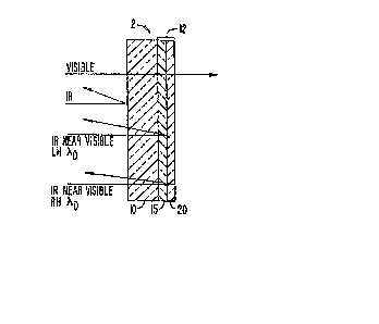
Refer now to Figure lA, which discloses an optical
filter according to the invention. The optical filter 2
includes an infrared absorptive filter element 10 and a
cholesteric liquid crystal filter element 12. Although the
invention is shown in Figure lA as including an infrared
element 10 in combination with a cholesteric element 12, it
should be understood that other filter elements may be
substituted for the infrared element and combined with the
cholesteric filter within the scope of the in~ention. The
physical arrangement of the filter elements may be modified,
for example as shown in Figure lB, within the scope of the
invention.
Infrared filter element 10 may be made, for
example, o~ glass, and may be a CM 500 infrared absorptive
filter, available commercially from Hoya, Inc. of Fremont,
California.
The cholesteric liquid crystal filter 12 includes
a first cholesteric liquid crystal element 15 and a second
cholesteric liquid crystal element 20. Elements 15 and 20
are disposed on infrared filter element 10 in a series
relationship. As an alternative, liquid crystal elements 15
and 20 may be disposed on opposing sides of infrared filter
element 10, as shown in the embodiment of Figure lB. Films
,; ; - . . - ~
:.
.
:
~ i32574~
15 and 20 are matched pairs of cholesteric films that
reflect left and right handed circularly polarized light
respective, over a precise bandwidth.
As further shown in Figures lA and lB, panchro-
matic light from a source (not shown) impinges opticalfilter 2 during use of filter 2. The light includes visible
light and infrared light, and in particular includes nearly
visible infrared light at a wavelength ~ 0.
Infrared filter element 10 blocks transmission of
1~ light over most of the infrared spectrum and begins to block
transmission of infrared light at a corner wavelength
slightly above ~0. "Corner wavelength" as used herein means
a wavelength at which an optical filter begins to block
transmission of light.
The cholesteric liquid crystal element 15 is ieft-
hand circularly polarized and reflects left-hand circularly
polarized infrared light in a defined band that includes
wavelength ~0.
Cholesteric element 20 is right-hand circularly
polarized and reflects infrared radiation of right-hand
circular polarity in the same band about wavelength ~ 0.
The cholesteric films may be made for example of
cholesteryl chloride (CC) and N-p-ethyotybenzlidene-p-n-
butyl aniline (EBBA) liquid crystals. The CC is a
cholesteric liquid crystal and the EBBA liquid is a nematic
liquid crystal. The ratio o~ the CC to the EBBA may be
70:30 by weight.
The cholesteric elements are designed such that
the reflective band about ~O has a bandwidth that does not
extend into the visible region. Thus, the embodiments of
the invention shown in Figures lA and lB transmit visible
light but completely reflect infrared light according to the
characteristics of infrared filter element 10 and the
reflection characteristics of the cholesteric elements about
wavelength ~0.
Refer now to Figures 2A and 2B.
, .,.. , ,: - , ~:
. .: . .
; , ,, . :
~ 1~2~7~
Figure 2A shows a goggles assembly according to
one embodiment of the invention. The goggles assembly 30
includes a frame 34, an eyepiece 32 and a band 36. The
goggles assembly may be, for example, night vision goggles
used to block visible light while transmitting infrared
emissions. In this emhodiment, eyepiece 32 includes a
cholesteric liquid crystal filter in combination with a
visible light filter element for blocking visible light and
only transmitting light in the inrared region.
Figure 2B shows an eyepiece 32 according to one
embodiment of the invention. The eyepiece 32 includes an
infrared filter element 10 which is composed of gl~ss. The
cholesteric elements 15 and 20 are deposited on infrared
filter element 10 in series to form eyepiece 32.
It should be understood that eyepiece 32 may be
formed as a lens element and thereby possess additional
optical faatures.
Refer now to Figure 3. Figure 3 shows a cockpit
40 which includes a plurality of light emission sources 55
and 65. Light emission sources 55 and 65 may be, for
e~ample, display systems which provide visible red light
output and spurious near visible infrared light output. A
viewer 70 in cockpit 40 may wear special goggles that are
designed to read data or symbology generated by displays 55
and 65 in cockpit 40. Unfortunately, spurious infrared
light from sources 55 and 65 may provide a false reading or
effectively blind viewer 70 to outside low level infrared
sources. According to the invention, high precision optical
filters 50 and 60 may be placed over sources 55 and 65,
respectively, to block transmission of infrared wavelengths
to viewer 70, thereby providing a cockpit having controlled
infrared emissions.
The invention will now be further explained by
reference to graphs which illustrate the optical output of a
typical color display and the performance and
characteristics of an optical filter system according to the
invention.
P~7' 132~741
.. ~
Refer now to Figure 4 which shows percent
transmission versus wavelength curves 100, llO and 120 for
an ideal infrared filter, a type 1 infrared filter, and a
type 2 infrared filter, respectively.
Also shown superimposed in Figure 4 is a spectral
output curve 200 for a display system which displays red
symbology. As shown in Figure 4, spectral output curve 200
includes a first peak 215 near 550 nanometers, a second peak
220 near 620 nanometers, and a third peak 225 near 700
nanometers. Peak 215 represents green light output, peak
220 represents the desired visible red light output, and
peak 225 represents nearly visible infrared light output.
Sinc~ peak 225 falls within the sensitivity range of typical
conventional night vision goggles, this infrared output may
blind or light up conventional night vision goggles. Thus,
it is desirable to eliminate peak 225.
One way to reduce the transmission of the infrared
light represented by peak 225 is to use a filter. An ideal
filter for this application would transmit visible light up
to the wavelength represented by peak 220 and would block
transmission of the nearly visible infrared light at the
wavelength represented by peak 225. Thus, the ideal filter
would have a corner wavelength between peaks 220 and 225 and
would have a transmissivity curve that transitions from just
below 100% transmission at the corner wavelength to 0%
transmission at peak 225. A performance curve 100 for such
an ideal filter is shown in Figure 4. Such a filter would
completely eliminate the nearly visible infrared light and
yet would not reduce the desired red light output from the
display. Unfortunately, such an ideal filter is not
obtainable in practice.
Performance curves 110 and 120, for type 1 and
type 2 infrared filters respectively, are also pictured in
Figure 4. As shown by curve 110, the type 1 filter
eliminates the nearly visible infrared peaks but has the
undesirable side effect of greatly reducing the intensity of
the red light output. As also shown by curve 120, the type
;';
.::
- . . .
:- ,. . : . . -
-` ' 132~7~
9 6~157-288
2 filter does not reduce the intensity of the red light in peak
220 but does not completely eliminate the undesirable infrared
light represented by peak 225.
Refer now to Figure 5. Figure 5 is a graph which
depicts the percent transmission versus wavelength for several
cholesteric liquid crystal filters. Curve 130 represents the
percentaye transmission for a right tor matched left-handed)
cholesteric liquid crystal filter. As shown in Figure 5, curve
1~0 has a transmission minimum at wavelength ~o. This minimum
corresponds to 50~ transmission, which indicates for a right-
handed cholesteric filter that right-handed circularly polarized
light will be reflected, and for a left-handed cholesteric filter
that left-handed circularly polarized light will be reflected.
~ urve 140 shows the performance for a matched pair of
right and left-handed cholesteric liquid crystal filters in
series. Curve 140 has a minimum transmissivity of O at frequency
~, which indicates that all light at this wavelength will be
reflected by each pair of cholesteric filters. Curve 150
illustrates the percent transmission versus wavelength for another
pair of matched right and left-handed cholesteric liquid crystal
filters.
The curves in Figure 5 illustrate the known propensity
of cholesteric liquid crystal elements to reflect 100% of
circularly polarized light of a yiven handedness near a nominal
wavelength, and to transmit the other handed circularly polarized
light w~thout attenuation near that same wavelength. The
cholesteric elements also have the useful property that their
transmissivity curves could be expected to transition very rapidly
from 100% transmission at a corner wavelength to their maximum
reflectivity within a relatively short bandwidth.
It is also known that such liquid crystal notch filters
may be made of a combination of cholesteric and nematic materials.
One method for determining the bandwidth of maximum reflectivity
is by controlling the amount of nematic material included in the
liquid crystal filter.
1: '
, . - . -: - . ... ~: -
: . . - . , -: :- . .
- : ~ . ,.. .. - : ... . . ~ , .: -
~, . . . ~ .
132~i74~ 64157-2n8
~igure 7 is a graph which illustrates the relationship
between percent nematic and cholesteric composition and the
wavelength of maximum reflectivlty (~n) .
Figure 5 al~o illustratec~ as shown by curves 14
alld 150, that differiny bandwidt1l~ can be achieved for the
cholesteric liquid crystal filter elements according to the
following formu~la:
DEL~A~ \ = DELTA N/N
where
DELTA ~ is the bandwidth,
N is the average index of refraction of the
liquid crystal film,
DELT~ N is the average birefringence of the
liquid crystal film, and
~0 is the wavelength chosen for maximum reflect-
ivity.
A typical value of N is 1.5. Delta N is typically
in the range of 0.05 to 0.25. Therefore, at a wavelength of
maximum reflectivity of 700 nallometer~, the bandwidth could
vary between 23 nanometer~ and 117 nanometer~ for thQse
sample value~ of DELTA N and ~. DELT~ N may ~e varied by
varying the proportion of nematic material included with the
cholesteric material in the liquid crystal film.
Refer now to Figure 6. Figure 6 is a graph
showing the spect~al output of the red, color display
3ystem, the transmissivity curve 120 for a type ~ infrared
- filter, and the transmis~ivity curve 150 for a cholesteric
filter superimposed thereon according to the invention. As
shown in Figure 6, the transmissivity curve 120 for the type
2 filter transmits all visible light and blocks lfght at
infrared wavelengths except for the nearby visible
wavelength represented by peak 225.
According to one particular embodiment of the
invention, a cholesteric filter is used in combination with
a type 2 filter. The type 2 filter blocks infrared light
except for infrared in the light range around visible and
peak 225. The cholesteric filter is designed to have a
~:
.
;, . : : ;
.: : ' '' '~`' ', ;~ ,
: . . - . : ,.. ,., . :.. . .
~ 132~7~1
11
maximum reflectivity around the wavelength represented by
peak 225, i.e., near 700 nanometers. The cholesteric filter
substantially blocks all wavelengths in the band roughly
from 660 nanometers up to approximately 740 nanometers,
i.e., over an 80-nanometer bandwidth. The cholesteric
filter transmits light at all other wavelengths outside this
band essentially unattenuated. Thus, the combination filter
provides a wideband flter having a precision not heretofore
available.
10Refer now to Figure 9. Figure 9 is a graph
depicting transmissivity curves for a number of liquid
crystal filters having a number of bandwidths as determined
by various of DELTA N values (i.e., birefringence values).
Transmissivity curve 180 is for a DELTA N of 0.5, trans-
15missivity curve 190 represents a DELTA N of 0.10, and
transmissivity curve 195 is for a DELTA N of 0.25. As DELTA
N increases the bandwidth increases, as is clearly shown in
Fig. 9.
One limitation of conventional cholesteric liquid
crystal filter elements is the tendency for the wavelength
of maximum reflectivity (~) to shift with temperature.
Figure 8 is a graph which depicts the wavelength of maximum
re1ectivity, ~O~ versus temperature. As can be seen from
Figura 8, as temperature increases, the wavelength of
maximum reflectivity for a given cholestericliquid crystal
filter decreases.
One reason for this unwanted shift in ~O is the
changing fluid properties of the cholesteric li~uid crystal
filter over temperature. According to one embodiment of the
invention, a polymeric cholesteric liquid crystal as
described in Patent 4,637,896 by Shannon, may be used to
stabilize the wavelength of maximum reflectivity over tem-
perature.
According to another embodiment of the invention,
another solution for resolving the problem of the shift in
~O for the liquid crystal filter is to make the bandwidth as
wide as possible while making sure that the bandwidth does
'` ' - ,' ': ' . . ' ' ' :: ~
- . ' ' ' ". . ' :
~ ~325~41
12
not overlap any wavelength for which transmis~ion is desired
as the bandwidth shifts over temperature. ~ccording to
another embodiment, ~0 may be shifted away from the spurious
wavelength by design to compensate for anticipated shifts in
S ~0 caused by operating temperatures.
It should be understood that the invention has
been described in detail with respect to various specific
embodiments. It should be recognized, however, that the
invention is not limited to the embodiments or applications
described herein, but rather that modifications, variations,
and other applications can be made in practice which are
within the scope of the invention. For example, some color
displays also output an infrared spike which is far out in
the infrared region, far past the nearly visible infrared
peak. Known filters for removing this far out peak would
also greatly reduce the entire range of infrared input. It
is possible according to the invention to overlay a
cholesteric li~uid crystal filter over a visible light
filter or use a single cholesteric liquid crystal filter
element for blocking this far out wavelength without
degrading the overall sensitivity of the night vision
goggles. Thus, according to the invention, it may be
desirable to emplo~ single or multiple cholesteric liquid
crystal filters, either alone or in combination with other
filter elements, as part of an eyepiece for night vision ap-
plications.
It is also within the scope of the inven~ion for
the wavelength of maximum reflectivity of the cholesteric
filter to be located either at, above, or below a corner
wavelength of a companion filter element within the scope of
the invention depending on design considerations, choice of
materials, sensitivity of the bandwidth to shifting
temperature, or the precision of the filter companion.
In some applications~ the use of a single
cholesteric film (rather than a matched pair) in combination
with a conventional wideband filter element may be adequate
,. ~:- . :
~ -: .
~ i32~7~1
13
for providing the required filtering precision i.e.,
transition from transmission to nontransmission.
In other applications, a single film or multiple
cholesteric liquid crystal films may be deposited on a lens
or other conventional eyepiece to form an eyepiece having
high precision optical filtering characteristics within the
scope of the invention.
Accordingly, it should be understood that the
invention is limited only by the appended claims.
,,
. -
,
. ,