Note : Les descriptions sont présentées dans la langue officielle dans laquelle elles ont été soumises.
1 325888
LIFT SYSTEM FOR VEHICLE-MOUNTED IMPLEMENTS
Background of the Invention
The present invention relates to an improved work vehicle
and more specifically relates to lift systems for vehicle-
mounted implements.
Typically, a work vehicle such as a tractor is provided
with a lift system that is adapted for connection to an
implement mounted to the tractor frame for the purpose of
raising a lowering the implement between working and transport
positions. it is well known to embody helper springs in such
lift systems in order to keep the lift effort at a reasonable
amount. These helper springs are often adjustable to
accommodate for different types of implements having different
weights or mounting structure geometries, but some are not
easily adjustable and others are not arranged so as to effect
; a near constant lifting force throughout the range of movement
of the particular implement being raised and lowered, as is
desirable when the implement is relatively heavy, a rear-
mounted tiller or a front-mounted snowblower being examples of
such implements.
Summary of the Invention
According to the present invention there is provided a
vehicle in the form of a lawn and garden tractor having an
implement lift system for raising and lowering various types
of tractor-mounted implements between working and transport
. positlons.
An object of the invention is to provide a work vehicle
having a lift system adapted for raising and lowering front-
rear- or mid-mounted implements, the lift system incorporating
a lift assist including an easily adjustable lift assist
spring the effects of which may be locked out to permit the
entire weight of attached implements to bias them downwardly.
Another object of the invention s to provide a lift
assist, as set forth in the immediately preceding object,
which further includes an optional lift assist kit useable,
for example, when a snowblower is mounted to the work vehicle,
2 ~
1 325888
the lift assist kit including a gas spring arranged such that
the lifting force exerted by an operator when raising the
snow-blower from its lowered working position to its raised
transport position remains substantially constant.
These and other objects will become apparent from a
reading of the ensuing description together with the appended
drawings.
Brief Description of the Drawinqs
FIG. 1 is a right front perspective view of a tractor
embodying the present invention.
FIG. 2 is a right front perspective view showing the
improved lift system mounted to the tractor main frame.
FIG. 3 is a left rear perspective view of the improved
lift system of FIG. 2, but for the sake of clarity, showing
the tractor main frame in dashed lines and with portions
omitted.
FIG. 4 is a right side elevational view of the lift
system of FIG. 2 but further showing the lift system coupled
to a partially shown, rear-mounted rotary tiller.
FIG. 5 is an exploded, left rear perspective view
showing a portion of the improved lift system of the tractor.
FIG. 6 is a right front exploded view of a gas spring
lift assist which optionally may be incorporated in and form
part of the lift system shown in FIG. 2.
FIG. 6a is a partial schematic view of the gas spring
shown in FIG. 6, with the gas spring being shown in its
maximum assist position corresponding to a raised position of
a front-mounted implement.
FIG. 6b is a view like 6a, but showing the gas spring in
its minimum assist position corresponding to a lowered
position of a front-mounted implement.
FIGS. 6c-6e respectively show graphs of the tension
spring assist force versus implement position, the gas spring
assist force versus implement position and of the combined or
resultant tension and gas spring forces versus implement
position.
Description of the Preferred Embodiment
Referring now to FIGS. 1 and 2 of the drawings, there is
shown a work vehicle in the form of a tractor 20 having a
longitudinally extending main frame 22 including transversely
spaced, longitudinally extending right and left side frame
members 24 and 26, respectively, joined together by a
plurality of cross frame members including a u-shaped rear
cross frame member 80 and having right and left crankshaft
; supports 102 and 104 welded to outer locations thereof just
forwardly of the cross frame member 80.
The main frame 22 is supported on a pair of front
steerable wheels 30 and 32 and a pair of rear drive wheels 46
- and 48. An engine (not visible) is supported on a forward
portion of the frame 22 in a compartment defined in part by a
hood 50.
Mounted to the frame 22 rearwardly of the hood 50 is a
combined operator platform and fender deck structure 68. A
seat assembly 76 is mounted to the structure 68 so as to
position an operator within easy reach of various controls
including a steering wheel 38 located forwardly of the seat
and a lift lever 100 projecting through a right hand fender of
the structure 68 and forming part of an implement lift system
40.
Referring now also to FIGS. 3-6, it can be seen that the
lift system 40 is mounted on the vehicle frame 22 for raising
and lowering implements carried by the frame. The details of
the different implements and their connections to the frame 22
are the subject of co-pending Canadian application Ser. No.
559,480 filed on 22 February 1988. Specifically, the lift
system 40 comprises a plurality of horizontal, transverse
rockshafts including a rear rockshaft 108, a mid-mounted set
of rockshafts 117 and 118 and a forward rockshaft 150. The
rear rockshaft 108 is journalled in the left upright support
104 and in a bracket 103 fixed to an upper rear location of
the right upright support 102.
The mid-mounted rockshaft 117 has opposite end portions
journalled in the side members 24 and 26 while the rockshaft
1 325888
118 is tubular and is received over the rockshaft 117 for
oscillating thereabout. Support plates are secured to and
depend from outer forward surface locations of the frame side
members 24 and 26 and the forward rockshaft 150 is journalled
in the support plates. A plate-like crank arm 116 is fixed to
the rockshaft 108 at a location just inside the support 102.
As can best be seen in FIG. 5, right and left hand arms
127 and 129, respectively, are fixed to the rockshaft 117
adjacent opposite ends of the outer rockshaft 118, the arm 127
being in substantial fore-and-aft alignment with the arm 116.
Oscillating motion of the rear rockshaft 108 is transferred to
the inner mid-mounted rockshaft 117 by a link 122 having its
rear end pivotally connected to the arm 116 by a pin 124 and
having its forward end pivotally connected to the arm 127 by a
pin 126. Respectively fixed to the right- and left-hand ends
of the outer mid-mounted rockshaft 118 are a bell crank 120
and a crankarm 134, the bell crank 120 being coupled for being
moved by motion of the link 122 by the pin 126 which projects
into an arcuate lost-motion slot 128 provided in the crank
120. The bell crank 120 includes a forwardly projecting leg
130 having an inwardly projecting pin or stud 132 connected
thereto. The crank arm 134 is in the form of a triangular
;; plate and an inwardly projecting pin or stud 136 is connected
to a corner of the arm in axial alignment with the pin 132 and
cooperates with the latter for receiving respective ends of
implement lift links (not shown) associated with a mid-mounted
implement such as a mower, for example.
Fixed to the front rockshaft 150 at respective locations
inboard of the frame side members 24 and 26 are a crankarm
152, in the form of a triangular plate, and a crank arm 156,
in the form of a strap, the arms 152 and 156 being provided
with respective axially aligned apertures 158 for cooperative
attachment to respective lift links (not shown) of a front-
mounted implement such as a blade or snowblower, for example.
Motion of the outer mid-mounted rockshaft 118 is transferred
to the rockshaft 150 by a link 153 having its rear end coupled
to the arm 134, by a pin 138 received in an arcuate slot 139
,
.
1 325888
provided in the arm, and having its forward end coupled to one
corner of the arm 152 by a pin 154.
The lift handle 100 is provided for controlling the
raising and lowering of implements carried by the vehicle and
for controlling the operation of a latch mechanism 106' that
operates to selectively lock the handle in a lowered, lift
assist lockout position or a raised transport position.
Specifically, the handle 100 includes a handle frame 110
fixed, as at 111, to a right hand end of the rear rockshaft
108 and projecting upwardly through an opening provided in the
right hand fender of the combined operator station and fender
deck 68 of the vehicle. The handle frame 110 includes a
channel portion slidably supporting a rod 107 having a forward
end carrying a button 103 that is received in and projects
from a hand grip 101 that is fixed to a forward end of the
channel portion. A spring 105 is received on the rod 107 and
is compressed between the button 103 and a washer received on
the rod and captured by the frame 110 so as to bias the button
outwardly from the grip. The rear end of the rod is provided
with an in-turned end 107' located for engaging a tab 114' of
a latch-operating arm 114 that is mounted for rotating freely
about the shaft 108 with an inner end thereof bridging the
support bracket 103. Positioned adjacent the inner end of the
arm 114 and forming part of the latch mechanism 106' is a
latch 106 in the form of an upright plate having a
substantially semicircular clearance notch provided in a rear
edge thereof with the shaft 108 passing freely through the
notch. An arcuately shaped forward edge of the latch 106 is
interrupted by a dove tail shaped projection 112 which
cooperates with the arcuately shaped edge to define forward
and rearward notches 113' and 113. A latch strike or bar 109
is bolted to an inner surface of the support 102 and has an
upper arcuate surface 121 against which the projection 112
moves when passing between a transport latch position wherein
the rearward notch 113 is engaged with a forward end of the
strike 109 and an assist lock-out latch position wherein the
forward notch 113' is engaged with a rearward end of the
,~
1 325888
strike lO9. Motion of the arm 114 is transferred to the latch
106 by a link 115, the forward end of the link carrying a pin
received in an aperture provided in an upper forward location
of the latch 106 and a mid location of the link being pinned
to the arm 114.
An adjustable lift assist 140' is provided for
counterbalancing the weight of either mid- or rear-mounted
implements that are coupled for being raised and lowered in
response to rocking the rockshaft 118. Specifically, the
assist 140' includes a coil tension spring 140 having a hook
at its forward end connected to the arm 129 carried by the
left end of the inner mid-mounted rockshaft 117. The rear end
of the spring 140 has a spring retainer 142 secured thereto,
the retainer being provided with a threaded hole receiving a
threaded end of a manually operable screw crank 144 that is
rotatably mounted in a tab 146 connected to and projecting
upwardly from an upper left hand portion of the web of the
rear cross frame member 80. An abutment 148 is fixed to the
screw crank 144 and engages the tab 146 so as to prevent the
crank from shifting forwardly in the tab. Thus, the spring
140 exerts a pulling force on the arm 129 which, by virtue of
the shaft 117, arm 127 and pin 126, results in a lifting force
being applied to the bell crank 130 and, by virtue of the
shaft 118, results in a lifting force being applied to the
crank arm 134.
It is desireable that some implements, a tiller for
example, operate with the full weight thereof biasing them
toward the ground. This result is accomplished in the present
invention by locking out the lift assist 140' by rotating the
lift handle 100 downwardly sufficiently far that the latch
projection 112 moves past the rear end of the strike 109
whereupon the latch notch 113 becomes engaged with the end of
the strike. Release of the latch 106 is effected by pushing
down on the handle 100 to release the tension on the latch and
then by depressing the button 103 to cause the rod end 107' to
rotate the arm 114 and disengage the latch notch 113 from the
strike 109.
~.
1 325888
When a relatively heavy forward-mounted implement such as
a snow blower, for example, is coupled to the vehicle, it may
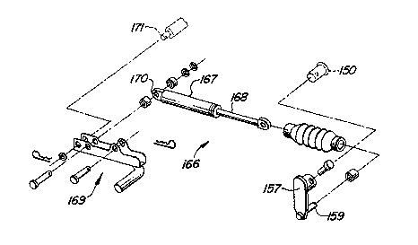
be desirable to provide an auxiliary lift assist 166, as shown
in FIGS. 6-6b. Specifically, the lift assist 166 comprises a
gas spring including a cylinder 167 and a piston rod 168, the
latter being pivotally received on a stud 159 carried by a
crank arm 157 that is removably pinned to the right hand end
of the rockshaft 150. The cylinder 167 is received within a
channel shaped frame 169 and has an apertured connector 170
joined to its rear end and pinned to the frame. The rear end
of the frame 169 is in turn pivotally received on a stud 171
projecting rightwardly from a frame (not shown) forming part
of the forwardly attached implement, the latter being latched
to out-turned implement attachment studs or pins 119 carried
by supports fixed to outer surface portions of the vehicle
frame side members 24 and 26 at a location spaced forwardly of
the mid-mounted rockshafts 117 and 118. The geometrical
relationship of the crank arm 157 to the crank arms 152 and
158, to which lift links of a forwardly mounted implement
would be attached, is such that when the implement is in a
lowered position (FIG. 6b) the gas spring is in substantial
alignment with the rockshaft 150 and thus does not exert much
lifting force. As rockshaft 150 is rocked to raise the arms
152 and 158, the assist force increases. The graph depicted
in FIG. 6d shows this increase in force as an implement is
raised. This arrangement of the gas spring is important when
operating a snowblower, for example, since it is desired that
the full weight of the snowblower act to aid in snow being
scraped from a driveway or sidewalk, for example. Of course,
the lift assist 140' will be locked out at this time. When it
is desired to raise the snowblower for transport, the lift
handle 100 is operated to place the lift assist 140' into
operation. It will be appreciated that the spring 140 is at
its maximum stretch and hence exerts maximum lift assist when
an implement is completely lowered and that this assist
decreases as an implement is raised. This operation is
graphically depicted in FIG. 6c. FIG. 6e graphically shows
,o~
~ 1 325888
that the resultant of the lift assist force provided by the
spring 140 and the gas spring 167,168 over the lift range is a
constant force thereby making it possible for an operator to
lift a relatively heavy implement by exerting only a
relatively moderate constant effort.
An adjustable depth stop 160 is incorporated into the
lift system 40 for the purpose of controlling the height of
cut of a mid-mounted mower, for example, and includes a knob
161 fixed to the upper end of a threaded rod 162 extending
vertically through an aperture provided in a support plate 163
which extends between and is fixed to upper surface portions
of the frame side members 24, 26. Fixed on the rod 162 is a
collar which prevents the rod from shifting downwardly through
the aperture. A yoke 164 is adjustably threaded onto the
lower portion of the rod 162 and has opposite legs located on
opposite sides of the bell crank 120 and joined together by a
pin 165' that is received in an upright lost-motion slot 165
provided in the bell crank 120. Thus, it will be appreciated
that maximum depth will be provided by turning the knob to
dispose the pin 165' in the bottom of the slot 165 when the
hand lever 100 is in the raised position, this condition being
shown in FIG. 3. Lesser depths can, of course, be established
by positioning the pin 165' at other locations within the slot
165.