Note : Les descriptions sont présentées dans la langue officielle dans laquelle elles ont été soumises.
-1l 325889
Gas Resonance_Device
In an oscillating column of gas a small region of
the gas is initially displaced in one direction, is
compressed, moves back in the opposite direction, and
expands. During compression the gas is heated and,
i during expansion, is cooled. When such an oscillating
column of gas is brought into contact with a stationary
solid medium, heat transfer takes place between the gas
and the medium. When the medium has a high effective
heat capacity compared with that of the gas and a low
thermal conductivity in the direction of advancement of
oscillations of the gas, it stores heat acquired as a
result of the adiabatic compression of the gas and then,
returns this stored heat to the gas after its expansion.
Whilst this is true for regions of gas which are always
located adjacent the medium a different situation exists
at the ends of the medium. At the downstream end of the
medium, when considered in the direction of advancement
of the oscillation, a region of gas which is in thermal
contact with the ends of the medium is moved in the one
direction away from the medium and compressed during
oscillation. The gas is heated upon compression. Upon
subsequently moving in the other direction and expanding
it returns to its position adjacent the end of the
medium. Here, since it cools during expansion, it once
again accepts heat from the medium. This gives rise to a
region of heated gas downstream from the downstream end
of the medium. Conversely, at the upstream end of the
medium particles of gas which are not normally in contact
with the medium move forward in the one direction during
the oscillation are compressed and heated and then in
~ their forwards position are in thermal contact with the
-~ medium so giving heat to the medium. As this region of
gas moves backwards in the opposite direction to r ~ rn
, .
- 1 325889
--2--
to its initial position, it expands and cools. Since in
their initial position the particles of gas are out of
thermal contact with the medium this gives rise to a cold
region upstream from the upstream end of the medium.
Such a medium located in an oscillating gas column
is usually referred to as a regenerator and is often used
with Stirling cycle engines. Typically such a
regenerator must have as large a surface area as
possible, a high effective heat capacity compared with
that of the gas and a low thermal conductivity along the
direction of gas motion. Conventionally pads of randomly
close-packed metallic wire have been used as a
regenerator but it is also possible to use closely packed
stacks of non-metallic plates and these are more
efficient with regard to gas friction losses and heat
transfer. Thus, the use of a regenerator enables a
temperature difference to be established from an
oscillating gas flow. Conversely, it is also known that
if a temperature difference of sufficient magnitude is
applied across such a regenerator oscillations are
spontaneously induced in gas surrounding such a
regenerator.
It is also known that oscillations can be
established in a column of gas located in a resonance
chamber by simply applying heat to one end of the chamber
if a sufficiently high temperature differential is
established. As examples of this gas in an organ pipe
can be made to resonate by a hydrogen flame in the base
of the pipe as described by Higgins as long ago as 1777,
and the Taconis oscillations reported in 1949 experienced
when placing a tube at room temperature into a cryogenic
storage vessel.
A reasoned discussion of these effects is given in
an article by Wheatley, Hofler, Swift and Migliori
entitled "An intrinsically irreversible thermoacoustic
-3- 1 325889
engine" published in the American Journal of Physics
Volume 53 ~2) February 1985, at page 147.
According to this invention a thermally driven gas
resonance device comprises a resonance tube which expands
in cross-section along its length from one end to the
other, a heat source located at the one end of the
- resonance tube, and means to trigger oscillations in a
gas in the resonance tube.
The heat source may be formed by a simple, indirect
heater in which the source of the heat such as an
electrical heating element or a gas or oil burner
assembly is used to heat a plate forming or located in
the one end of the gas resonance tube. Preferably the
heated plate is finned to improve the heat transfer from
it to the gas at the one end of the resonance tube. A
regenerator may be located in the resonance tube close to
but out of contact with the heated plate and from the
means to trigger the oscillations. The regenerator
consists of a material having a large surface area, a
high effective heat capacity compared with that of the
~`~ gas in the resonance tube and a low thermal conductivity
along the length of the resonance tube, the arrangement
being such that, in use, the heat source sets up a
temperature gradient along the regenerator which triggers
the oscillations of the gas in the resonance tube.
However, it is very much preferred that the heat
source and the means to trigger the oscillations in the
gas in the resonance tube are both formed by a pulsed
heat source having a pulse repetition frequency
corresponding to a resonant frequency of the gas
resonance tube. Such a pulsed heat source may comprise a
pulsed combustor or a resonant flame fed with a premixed
supply of inflammable gas or vapour and air through a
; valve, followed by a flame trap, and an ignitor intially
to ignite the mixture in the one end of the resonance
1 325889
-4-
tube or in a combustion chamber leading into the
resonance tube. Preferably the valve to admit the
mixture is formed by a tuned non-return valve which, in
response to the pulsed combustion, oscillates between its
open and closed states to admit bursts of mixture into
the one end of the resonance tube or combustion chamber
for subsequent ignition. The use of the pulsed heat
source to trigger the oscillations in the gas in the
resonance tube provides easy starting under wide range of
conditions, followed by stable resonant operation. The
ignitor may be formed by a sparking plug to cause initial
ignition of the pulsed heat source but, once ignited the
pulsed heat source is preferably self-sustaining. This
may be as a result of subsequent bursts of mixture being
ignited by the fading flame from a preceding combustion
pulse, by spontaneous ignition as a result of a
compression wave or by the ignitor having the form of a
glow plug which provides a local hot spot to cause
ignition.
The pulsed heat source may also include an indirect
heater located at the one end of the resonance tube. The
indirect heater may be formed by a heat exchange surface
heated by the pulsed heat source to spread the heat of
combusion substantially uniformly over the
cross-sectional area of the one end of the resonance
tube. Preferably when the gas resonance device includes
a pulsed combustor the one end of the resonance tube is
formed as a parabolic reflector which spreads the effect
of the pulsed combustion more uniformly over the one end
of the resonance tube. In this case the pulsed
combustion is arranged to take place substantially at the
focus of the parabolic reflector. When the gas resonance
device includes a pulsed heat source it may also include
a regenerator which co-operates with a temperature
~ 5 l 325889
..
gradient subsisting across it to amplify the oscillations
induced by the pulsed heat source.
With all of these arrangements to generate
oscillations in the gas it is necessary to arrange the
shape of the resonance tube both to provide the required
relative pressure and adiabatic temperature amplitudes of
the two ends of the tube and to minimise gas wall
friction losses which tend to inhibit the resonant
oscillations of the gas. By having the resonance tube
expanding in cross-section from its one end to its other
larger pressure and adiabatic amplitudes are developed at
` the small relative to large end and this is discussed in
detail dynamical subsequently. Preferably the resonance
tube is generally frustoconical in shape with the ratio
of base diameter to height approximately equal to 1:3.
Firstly this provides a diameter to length ratio for the
-~ longitudinal oscillation which can be thought of as a gas
piston to be as large as practical thereby minimising
wall friction losses. The resonant frequency of the
resonance tube depends mainly upon its length and is
independent of its shape. By making the resonance tube
increase in cross-sectional area from its one end to its
other end it is possible to increase the mass of gas
which oscillates and thereby decrease its velocity for a
given volume compression ratio. Friction losses are
proportional to the cube of the gas velocity and
consequently this reduces the friction losses
considerably to enhance the performance of the resonance
device. Preferably the resonance tube has a
frusto-ogival shape in longitudinal-section so that, when
seen in cross-section, its side walls are curved. This
provides a further increase in the mass of oscillating
gas closer to the one end and so enhances the reduction
in friction losses still further.
- 1 325889
--6--
The mechanical energy produced in the oscillating
gas in the gas resonance device may be used to operate a
pressure swing gas separator with a molecular sieve
material. One of the most straightforward arrangements
is to use the gas resonance device in an apparatus for
the pressure swing separation of oxygen from air. In
this case the other end of the resonance tube contains a
molecular sieve material, a gas exchange port is provided
on the side of the molecular sieve material towards the
heat source, and a gas outlet is provided upon the side
of the molecular sieve material remote from the heat
source. During oscillation as air moves forwards through
the bed of molecular sieve material nitrogen is
preferentially adsorbed by the molecular sieve material.
As the air moves backwards a reduced pressure is created
- and gases adsorbed onto the surface of the molecular
sieve material are desorbed. Thus, when the molecular
sieve material is subjected to the oscillations generated
in the resonance tube nitrogen, which is preferentially
adsorbed by the molecular sieve material tends to return
to the inside of the resonance tube and hence out of the
gas exchange port, whereas oxygen, which is less adsorbed
by the molecular sieve material, tends to be driven
through the bed of the molecular sieve material and out
of the gas outlet at the downstream side of the molecular
sieve material. The finite displacements of the gas that
occur during oscillation create a mean pressure slightly
above ambient in the resonance tube so that a continuous
flow of separated oxygen emerges below the bed of
molecular sieve material.
Typically the molecular sieve material is an
expanded zeolite but actuve carbon may also be used. The
molecular sieve material preferably has sufficient
surface area to permit a high nitrogen adsorbtion rate
and it has been found that the cumulative rate of
.
I 32588~
--7--
adsorbtion and desorbtion is proportional to pressure
swing and nearly independent of cycle rate.
In an alternative configuration the mechanical
energy produced in the oscillating gas in the resonance
tube is used to drive a heat pump. In this case the gas
resonance device includes a heat sink located at its
other end, a regenerator located adjacent the other end,
and means on the side of the regenerator towards the heat
source to effect heat exchange between the gas in the
; 10 resonance tube and a source of low grade heat.
With this arrangement the effects discussed earlier
are used to provide a heat engine driven heat pump. Thus
the oscillations in the gas in the resonance tube are
applied to the regenerator to produce a temperature
differential across it with the gas downstream of the
regenerator at the other end of the resonance tube being
heated and with the gas upstream from the regenerator
being cooled. The heat exchange that takes place
upstream of the regenerator prGvides the heat for the
expansion of the gas upstream from the regenerator and
provides the source of the heat which is pumped to
provide part of the heat removed by the heat sink at the
other end of the resonance tube. In addition to this the
heat sink at the other end of the resonance tube also
receives heat provided by the heat source. The applicant
has coined the acronym HASER to describe this type of
heat engine driven heat pump with the acronym standing
for "Heat Amplification by Stimulated Emission of
- Radiation" by analogy with the acronyms laser and maser.
When the source of low grade heat is the atmosphere,
it is preferred that a direct heat exchange takes place
; between the atmosphere and gas in a region upstream of
the regenerator. To provide this gas exchange ports are
~- provided in the wall of the resonance tube at the
position of a pressure null point. As the longitudinal
; -8- 5 1 325889
vibrations pass down the resonance tube the atmosphere
tends to be drawn into the resonance tube through the
ports after the compression oscillation has passed the
ports. The gas that is drawn into the resonance tube
from the atmosphere then mixes with the gas in the
resonance tube with a resulting heat exchange taking
place between the gas from the atmosphere and the gas
already in the resonance tube. The next oscillation then
tends to drive the now cooled atmospheric air out of the
ports.
Preferably however the haser also includes a fan to
drive air from the atmosphere through the gas exchange
ports into the resonance tube. Preferably an outer
chamber surrounds the resonance tube with the fan located
lS at the top, that is the end of the resonance tube with
the heat source, and a corrugated annular baffle adjacent
the gas exchange ports to direct air blown by the fan
through half of the ports and allow cooled air to leave
from the other half of the ports and flow through the
lower portion of the outer chamber. The air flowing
through the outer chamber absorbs heat given off from the
heat source and upper part of the gas resonance tube and
this heat is re-introduced into the system as part of the
low grade heat so further improving the heat output of
the haser.
The expansion of the cross-section of the resonance
; tube from the one end of the other has further advantages
in a haser. The relative cross-sectional areas of the
two ends determine the compression ratio developed at
them. A small cross-section leads to a high compression
ratio and vice versa. The effect of this can be derived
from acoustic theory of small displacements and is
developed for the particular example subsequently. The
expanding cross-section of the resonance tube from the
one end to the other leads to a high compression ratio
1 32588~
g
for the driving end and a low compression ratio at the
pump end and this provides the optimum thermal
efficiency.
The heat sink at the other end of the resonance tube
may comprise a shallow pool of water and, in this case,
; it is preferred that fins of a good thermal conductor
such as metal are in thermal contact with the pool of
water and extend in the space between the pool of water
and the downstream side of the regenerator. Such a heat
~` 10 sink has a good thermal contact with the hot gas
downstream of the regenerator. The water in the pool is
circulated around a system to carry the heat away from
the other end of the resonance tube and this circulation
system may include non-return valves on both sides of the
pool so that the water is driven around the system by the
pressure fluctuations inside the resonance tube acting on
the surface of the water in the pool.
Such a haser has particular application as a hot
water generator for use in heating and cooling a
residential building. The haser is typically located in
' the roof space of a building and, in winter, the roof
;` space is ventilated or air from outside ducted to it so
that air provides the source of low grade heat. The heat
sink at the other end of the resonance tube is used to
heat water to a temperature of say 40C and this water is
" used for domestic hot water requirements and is
circulated around a central heating system of the
building. During summer the haser is used to provide
cooling for the building by closing the ventilation of
;, 30 the roof space and opening cooling vents in ceilings of
the rooms below the roof space or ducting the air leaving
the haser to the rooms. Water from the heat sink at the
other end of the resonance chamber is used for domestic
hot water requirements and also is led away to a heat
exchanger outside the building where it is cooled. The
1 325889
--10--
resulting cool air discharged from the resonance tube
cools the roof space and, in turn, through the cooling
vents in the ceilings, or via the ducting cools the
building.
A pressure swing gas separator may be combined with
a haser by placing molecular sieve material in the
resonance cavity above the regenerator. With this
combination the output from the outlet ports is cool and
rich in nitrogen. Such an output is good for preserving
perishables and such a combined device provides a readily
portable, self-contained source of nitrogen enriched cold
alr .
A particular example of a haser in accordance with
this invention will now be described with reference to
the accompanying drawings, in which:-
Figure 1 is a partly sectioned side elevation of a
pressure swing gas separator;
Figure 2 is a partly sectioned side elevation of a
haser;
Figure 3 is a cross-section throùgh a heat source;
Figure 4 is a diagram illustrating the dimensions of
the resonance tube and the gas displacements;
Figure 5 is a graph showing the characteristics of
- the resonance tube;
Figure 6 is another graph illustating how
displacement and density amplitudes vary with respect to
time over the length of the resonance tube;
Figure 7 is a further graph illustrating the effect
of ogival correction; and,
Figure 8 is a temperature against position diagram
- to illustrate the operation of the regenerator.
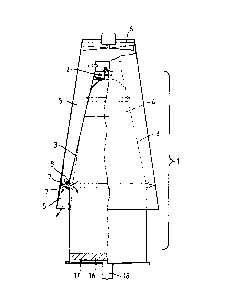
Both the pressure swing gas separator shown in
Figure 1 and the haser shown in Figure 2 include a heat
engine 1 formed by a pulsed heat source 2 mounted at one
end of a resonance tube 3 which is ogival in longitudinal
.,
t 325889
--11--
section. The overall dimensions of the resonance tube 3
are such that its height is about three times its base
diameter. A regenerator 4 may be included towards the
top of the resonance tube and this is made from a
non-metallic honeycomb which is typically made from glass
or a glass-like material. An outer concentric annular
chamber 5 surrounds the resonance tube 3 and an
electrically driven fan 6 is mounted at the top to blow
air downwards through the chamber 5. A corrungated
annular baffle 7 directs the flow of air through
alternate open ports 8 provided in the side wall of the
resonance tube 3 at a pressure null point. Air is
discharged through the other ports 8 and a lower portion
of the outer chamber 5. The open ports 8 produce orifice
flow and therefore inwards air flow through alternate
ports 8 is strongly converging which ensures that charge
~,and discharge through the ports 8 is not unduly mixed.
-The pulsed heat source 2 is shown in more detail in
Figure 3 and comprises a gas mixing space 9 to which gas
and air are supplied and in which they are mixed, a
resonant non-return valve 10 of similar resonant
frequency to that of the resonance tube 3, and a flame
trap 11. ~he resonance non-return valve 10 may be
similar to those fitted to two-stroke engines and
comprise an open port 12 covered by a springy plate 13
which is fixed along one edge to the port 12. ln
-response to the instantaneous pressure in the resonance
tube 3being greater than that in the gas mixing space 9
the valve is held closed with the springy plate 13
forming a seal against the edges of the port 12, and in
response to an instantaneous reduction in pressure in the
resonance tube 3 with respect to that in the gas mixing
space 9, the springy plate 13 bends to allow the gas and
air mixture to pass through the port 12 and into the
resonance tube 3. In a preferred configuration which leads
.~
1 325889
-llA-
to gas mixture delivery more clo6ely in phase with the
resonance chamber compres8ion pul6e, thus to concomitant
improvement in pulsed combustion, the resonance
non-return valve con6ists of a metal disc of relativelY
lacge diameter, placed co-axially with the combustion
chamber, clamped at its edges to a slightly concave
bedplate in which the flame trap is centrally located.
Gas mixture is introduced at low pres6ure to an internal
annulus close to the clamped edges, and i8 thereby fed
radially inward6 in pulses towards the flame trap. The
disc is of such thickness that its natural frequency of
axial oscillation is lower than that of the resonance
cavity 80 that the combined effect of the gas damping
and the cavity pressure pulses is to produce
substantially antiphase oscillations of the disc at the
resonant frequency of the cavity. These oscillations
introduce gas mixture through the flame trap to the
combustion chamber at the time of pressure rise instead
of the time of maximum suction, and the former
diminishes the extent of premature combustion, which i~
inefficient with regard to heat engine operation.
The pulsed heat source 2 also includes
~,'
` 1 325889
a sparking plug 14 and the top of the resonance tube 3 is
formed as a parabolic reflector 15 which spreads the
effect of the pulsed heat source substantially uniformly
over the end of the resonance tube 3.
The heat engine 1 drives a gas oscillation down the
resonance tube 3 and the vertically oscillating mass of
gas functions as a piston producing pressure and
adiabatic temperature fluctuations at top and bottom of
the tube 3. The oscillations are tirggered by the
sparking plug 14 initially igniting the gas and air
mixture introduced into the top of the resonance tube 3
and then, as the gas in the tube 3 begins to resonate and
the valve 10 introduces successive bursts of mixture
these are ignited by the fading flame from the previous
ignition. This produces a pulsed combustion which, in a
device having a resonance tube of length about 1 m has a
repetition frequency of around 200 Hz. The regenerator 4
increases the efficiency of the heat engine 1 by
increasing the temperature of the top end of the
resonance tube 3 and increasing the amplitude of the
socillations produced.
The heat engine 1 just described may be used to
provide the mechanical energy input for a pressure swing
gas separator and, in this case, as shown in Figure 1 a
shallow bed 16 of a zeolite which preferentially adsorbs
nitrogen is placed towards the lower end of the resonance
tube 3 and the base of the resonance tube is closed by a
plate 17 including a gas outlet 18. During resonant
oscillation in the resonance tube 3 as the air moves
forwards into the zeolite bed 16 nitrogen is
preferentially adsorbed by the zeolite. As the air moves
backwards a reduced pressure is created and the gases
adsorbed onto the surface of the zeolite are desorbed so
that air rich in nitrogen is desorbed. As a result of
the finite displacements of gas that occur during
-13- 1 325889
oscillation the average pressure inside the resonance
tube 3 is greater than atmospheric so that a flow of gas
passes through the zeolite bed 16 resulting in a flow of
gas out of the output 18 which is rich in oxygen whilst
the flow of gas out of the ports 8 and through the lower
part of the chamber 5 is rich in nitrogen.
The heat engine 1 may alternatively be used to
provide the mechanical energy to drive a heat pump 19. A
heat engine driven heat pump has an overall
coefficient of performance (COP) where
low qrade heat out
COP = high grade heat in
in excess of unity, provided that the adiabatic
~` temperature ratio of the former significantly exceeds
:~ that of the latter. The heat output may also be directly
supplemented by heat rejected from the heat engine 1.
The heat pump part 19 of the apparatus comprises a
regenerator 20 which is made from a non-metallic
honeycomb which is typically made of glass or glass-like
material and a heat sink 21. The heat sink 21 is formed
by a shallow pool of water 22 in the large diameter end
of the resonance tube 3 and metallic fins 23 in thermal
contact with the shallow pool of water 22 extend into the
resonance tube 3 towards the regenerator 20. Air, which
in this case provides the low grade source of heat enters
and leaves through the ports 8 and heat is extracted from
this air by the heat pump 19 and transferred to the water
22 in the heat sink 21.
Thus, in operation, gas oscillations are induced by
. the heat engine 1 inside the resonance tube 3. These
: 30 oscillations provide the driving power for the heat pump
19 including the regenerator 20. As the gas oscillates
around the regenerator 20 the space beneath the
regenerator 20 is heated and the space above the
regenerator 20 cooled. Air flow through the ports 8
mixes with the gas in the resonance tube 3 and gives heat
~14- ~ 325889
to the gas in the resonance tube 3 above the regenerator
20. The heat sink 21 removes the build up of heat
beneath the regenerator 20.
Typically the level of the shallow pool 22 of
circulating water in the heat-sink 21 is controlled by a
float valve (not shown). A water inlet and outlet for
the pool 22 includes non-return valves (not shown) and
the gas oscillations set up in the resonance tube 3 act
on the surface of the water in the pool 22 and cause
i10 circulation of the water through the inlet and outlet
non-return valves. Typically the water outlet
temperature is about 40C and this can be used as a
source of domestic hot water or a source of hot water for
driving a central heating system. Typically a haser as
~-15 shown in this example is mounted in the roof space of a
;house which is ventilated in the winter to allGw air from
the atmosphere to provide the source of low grade heat
entering and leaving the ports 8. If desired to cool the
~;jbuilding during the summer months, ventilators for the
roof space would be closed and ceiling louvres opened to
allow the cold air generated by the haser to gravitate
'into the house. In this case the hot water discharged
-from the heat sink 21 is, after the needs for domestic
~`hot water have been supplied, passed to an atmospheric
heat exchanger out of doors to dissipate the heat
generated in the haser before being recirculated. The
target value of the COP for such a haser would be 2 in
the heating mode.
The details of the gas resonance dynamics, the
desirability of the ogival shape of the resonance
chamber, a discussion on the wall friction losses, and a
discussion on the characteristics of the regenerator 20
will now be provided.
:,. .
- 15 ~ 1 3258 8 9
The Dynamics of Gas Resonance
It is necessary to develop a quantitative treatment of
gas motions in order to design a haser. Linear elastic
displacements of a uniform solid or fluid in a parallel
configuration (Figure 3a) are governed by the well-known
equation:
~2a a2
at2 = C2aX2 (1)
where a is displacement at reference distance x, t is time
. lapse and c is velocity of sound. For a standing wave in a
tube with closed ends where cross-section is also uniform,
a is proportional to:
~X . ~Ct
sin i sln
The corresponding governing equation for spherical
symmetry, applicable to oscillatory flow in a truncated
cone, has been known since the times of Cauchy and Poisson,
and is:
r)~ = C2aa(r~) ~2)
where r is defined as in Figure 4b. In both cases
/ - Po
. c - ~ p
where y is the ratio of specific heat and pO is the mean
pressure at which density is pO~ When the cone is
truncated at the radii b and a it may readily be verified
that a standing wave solution with arbitrary constant A is:
r~ = A SiD 1 (r-b) ~in
,
so that:
sin ~ (r-b)
a = A ~r sin ~1 (3)
1 325889
-16-
which becomes zero both at r=b, and r=a since a-b=1. It
is convenient in the following to put:
lrr 3 1 90~ 1 = 9, 1 = 1~ ~ and 1 = 1I~, 90 th~t'
`: 5
9 = U 8i D (9--90) ~1D ~t
a~ ~
~' iæ a maximum when a ~ = o, hence when a = tan ~-60),
which can be solved in terms of 60 for particular values
of 6, as in Figure 5, noting that
.. b 60 9- 6
a ~ ~ 9 and d = O
where d is the distance of the maximum position from the
small end.
Neglecting second order small quantities it may be
shown that the instantaneous density ratio is:
~' -1
2 0 P = [ 1 , 2~ 1 a
gin (6- 9 ) ~~
~ cos wt icos (9- 60) i e ~ (5)
which is unity when 6 = - tan (6-60), and is solved in
the same way to calculate dl with results plotted in
- Figure 5. It is seen that maximum displacement and
~; velocity occur at a position displaced from the midpoint
towards the small end of the cone, and the density and
pressure null point is displaced by a corresponding
distance towards the large end.
The extreme values of o from equation 5 are
obtained when cos ~t and cos (~-60) are both +1, so that
volume compression ratios mO and ml may be defined,
relating to the small and large ends respectively. Then:
-17- 1 325889
b 1 + A
m = _ m = -- (6)
If mO and ba are specified, A may be eliminated by the
deduction from equation 6 that:
A o
: b m I 1 -
o
Then~
m - 1
1 + a~
~ ml = 1 b o
; 15 a-m + 1 (7)
Furthermore, it may be deduced from equations 3 or 4, in
combination with Figure 5, for any point distance x from
the small end that:
. 20
25 In particular, x = d for maximum displacement or
velocity, and x = d' for the corresponding displacement
or velocity at the null point of density or pressure
change. However, when taking into account the finite
displacements as in the plot of extreme values of P
x po
against 1 shown in Figure 6, it is seen that the actual
value of Po at the null point is proportionally reduced
relative to the unit reference value. The value of this
proportional reduction ~Po may be calculated from the
slope of the curves derived from equation 5, referred to
` 1 325889
-18-
the null point and multiplied by the relevant
displacement. Thus:
Po (1 )
obtained from equation 8 with x = d'. It may be noted
from this that there is an equivalent excess mean density
and pressure for open cycle applications, since inflow
~` and outflow must be balanced.
The preceding analysis is based as stated upon
linear-elastic relationships, which are realised with
gases only for small displacements. Adiabatic behaviour
is non-linear, but the effects of the non-linearity have
been extensively studied for free piston applications,
and found to be significant only for high compression
ratios, which are themselves marginally increased from
values calculated by linear elastic methods, and time
rates of change are momentarily increased, so that
frequencies are somewhat higher than calculated. The
linear theory successfully predicts the location of the
pressure null point in experiments with the oscillating
haser, but observed resonant frequncies are higher than
predicted values, consistent both with the aforementioned
non-linearity of adiabatic gas compression, and the
increase of sonic velocity with temperature in the upper
part of the resonance tube. It may therefore be claimed
$ that the theory as presented is sufficiently accurate to
be used with confidence, and that corresponding
proportional adiabatic excursions of pressure and
absolute temperature may be obtained from the
proportional density excursions by raising the latter to
the powers y and y-l, respectively.
-19- 1 325889
Coefficient of Performance
. _ .
Since the Carnot thermal efficiency at the heated
end, determined from the ratio of absolute temperatures
in the cycle, is:
mOy 1 -1
Y-1
and the corresponding heat pump gain, determined from the
ratio of absolute temperatures in the cycle at the
absorber end, is:
mlr
r,
~: 1
:
,
it follows that the idealised coefficient of performance
is:
:
mO ~ 1 ~ y- 1
COP = Y-l y-l ~ (10)
mO
With r = 1.4 for air, this value for the example of
Figure 6 is 2.77, but it will be modified by several
; factors.
Firstly, it can be argued that heat is not rejected
at the low temperature corresponding with expansion at
the heated end, nor is it absorbed at a temperature
. corresponding with full compression at the absorber end,
- This is considered later with reference to the
regenerators where it is demonstrated that the function
of the regenerators is to lift the average temperatures
-20- 1 325889
at both ends, so that the ideal is more closely
approached.
- Secondly, although a proportion of the wall friction
;heat could be recovered with a water jacket, as in the
case with heat rejected at the heat engine end, the
former has to be provided as mechanical power subject to
the limited thermal efficiency of the heat engine
function, and is subject thereby to substantial leverage.
Mechanical power is also dissipated in the air entry and
discharge through the ports 7 and 8 but a proportion of
this is common to wall friction loss, since both are
concerned with the boundary layer.
The Ogival Shape Modification
The purpose of this for given end diameters is to
increase the mass of oscillating gas, thereby to decrease
its velocity for given volume compression ratios. The
effect is worth incorporation since friction loss is
proportional to the cube of velocity. A full numerical
analysis would be feasible, but the effect is likely to
be contained adequately within a correction.
The key to the correction procedure is found in the
first order dependence of natural frequency f on length
1, irrespective of shape, whether parallel, conical or
ogival, such that:
f = c
Angular frequency ~ for an oscillating system is also
k
~ = ~ m
where k is stiffness and m is mass so that, in the ogival
case, stiffness must be considered to be increased by the
same proportion as mass. The consequence of this is seen
in Figure 7, where there are three notional concentric
cones OA, OB and OC. OA is that which contains the
diameters of the two ends, and OB circumscribes the
- 1 325889
-21-
ogival curve. OC is an interpolation. It will be
recognised that the preceding theory is unchanged in
relation to the three cones, since all have the same
ratio ab. Cone OC intercepts the ogival curve to define a
5 mass zone and two stiffness zones. If the diameter ratio
between OA and oC is 1 + e, it follows from
considerations of volume and cross-setion area that the
stiffnesses are also increased by the ratio 1 + e.
However, irrespective of the definition of e the enclosed
volume designated as mass is increased by a ratio in
excess of 1 + 2e, and this anomaly can be explained in
terms of the hydrodynamic concept of virtual mass, which
`~ in this case is negative because of velocities which are
lower within the enlarged cross-section. Since stiffness
can be calculated without ambiguity it is appropriate to
consider that both stiffness and apparent mass are
increased by 1 + e, and that OC is defined as the neutral
axis of the ogival curve between the two ends (equal
surface area), such that BC = 2e. Then the ogival shape
behaves in relation to friction loss but not to
compression ratio or output as though it is a cone with
diameters increased in the ratio 1 + e, but with peak
velocities decreased in the ratio
The effect of the ogival shape shown in Figures 1 and 2
is to reduce friction loss by 50% for circumstances which
are otherwise equivalent.
Wall Friction Losses
In the absence of specific data fGr oscillatory flow
in cones, it is appropriate to consider steady state
boundary layer friction in a parallel pipe of equivalent
length and diameter. The friction coefficient c~ depends
upon Reynold's number and proportional surface roughness,
and is given by the standard data of Nikuradse. For the
I 325889
-22-
Reynold's numbers >106 and surface roughness <50 micron,
a suitable value for Cf would be 0.0035.
If the axial displacement in a cylindrical tube of
: radius R and half wavelength l is given by:
cos 1 cos ~t
the axial velocity u = ~ , the wall shear stress Cf P2 and the local
instantaneous work rate Cf P2 ~he sverage work rate ~, lntegrated
over the length of the tube and wlth respect to tlme, ls~
W ~c5pRI~ 1O [- ~ ~S dP._ ¦ DlD ~ ]
Noting that the b-acketed quantlt9 18 ~ (r 2 ))) and evaluatlng the
Gamma functlons, ( '5
~ = 0.566 cfPR1
-~ 3
Pul .
::.'., 20 CrA 2 , where ul = 0.565uo, (11)
uO is the amplitude of axial velocity and A is total area
of wall.
Expressed as a fraction n of the maximum kinetic
energy of the gas in the tube, the accumulation of
friction work over a half stroke is:
0.72 ~c~ (12)
n =
These considerations show that, although wall friction
losses are a significant fraction of the developed
mechanical power, they are containable particularly if
the ogival shape is incorporated.
Characteristics of Regenerators
Regenerators have been used since Stirling cycle
1 325889
-23-
engines were first constructed, and it is accepted that
they confer large increases of efficiency. Their
function as thermal filters is to store heat acquired at
one part of a reciprocating cycle as gas is passed during
an adiabatic volume change, and to return it to the gas
as the cycle is reversed. Their two essential properties
are thus a large surface area exposed to the gas, coupled
with a small thermal conductivity in the direction of gas
motion. Typically they have the form of stacks of spaced
non-metallic plates since these are efficient with regard
to gas friction losses and heat transfer.
The beneficial use of regeneration in the present
case may be seen from a plot of extreme values of
adiabatic temperature change (Figure 7) developed from
-~15 the corresponding plot of density ratios in Figure 5.
The sloping lines in Figure 7 quantitatively depict the
paths taken by packets of gas undergoing adiabatic
temperature changes, but in a reversible manner for
`simplicity, since in practice the lines would be loops
acounting for heat transfer. The positions of
regenerators 3 and 4 are shown, and it may be noted that
these do not extend to the ends of the resonance tube
where the heat transfer surfaces are placed. The gaps
between are sufficient to avoid thermal contact.
The lines BB' and EE' represent gas packets which
always remain within the regenerators. These packets
pump heat against a temperature gradient by acquiring it
when expanded and cold at positions towards the centre of
the cavity, and releasing it by heat exchange when
compressed and hot at positions towards the end of the
cavity. Thus, there are temperature gradients within the
regenerators, which slope up towards the ends of the
cavity. The mean temperatures of the regenerators are
also above ambient because heat exchange from compressed
gas is more effective than from rarefied gas.
/
1 325889
-24-
The most profound effect of the regenerators occurs
at their ends near to the ends of the cavity, because in
these positions gas enters when expanded and cold and
receives heat. It leaves as it becomes compressed and
hot, so that the mean temperature at the ends of the
cavity is significantly raised. The effect may be traced
with lines AA' and FF'. The reverse effect occurs at the
inner ends of the regenerators, as seen from lines CC'
and DD'. The overall effect is that mean temperatures
are significantly raised by as much as half the
temperature amplitude outboard of the regenerators, and
lowered by a smaller amount over a larger volume inboard
of the regenerators.
The regenerator length should exceed the gross
displacement at the preferred location, and the gap
between the lower regenerator and the heat absorber
should be the practical minimum. An optimal criterion
for the regenerator material is that the conductive heat
penetration depth for each cycle should not exceed the
strip thickness, and this is stated from the relevant
transient heat flow treatment as:
t ~ 2 ~ (13)
~o ~
For t = 0.1 mm and ~ = 817tsec, this indicates a
preferred thermal diffusivity ~ approximately equal to
cm /sec, which would be satisfied by glassy
materials. Metals are too conductive.
, .