Note : Les descriptions sont présentées dans la langue officielle dans laquelle elles ont été soumises.
13261 18
The invention relates to apparatus for molding
thermoplastic tubing, especially ribbed and double walled
thermoplastic tubing in which the ribs may be of helical
or annular configuration, or indeed any other
configuration.
The apparatus may be of the type in which tubing of
thermoplastic material is continuously extruded into a
travelling tubular mold tunnel about a mandrel and is
confined to the shape of the pipe by a sizing plug
downstream of the mandrel. Such a plug may on some
occasions, when extrudate does not easily flow fully into
the mold, be heated to increase the fluidity of the
extrudate so that it may more easily flow into recesses of
the mold, for example under the influence of suction from
the bases of the recesses. However, more usually the
extrudate is provided in sufficiently molten condition to
flow fully into the mold. In this case it is necessary to
provide a sizing plug to define the inner wall of the pipe
so as to confine the extrudate in an appropriate casting
cavity.
A simple follower plug defining the inner wall of a tube
is described by Chaplain in U.S. Patent No. 4,365,948
issued December 28, 1982. Usually some temperature
control is desirable in a sizing plug and Lupke in U.S~
Patent No. 4,545,751 issued October 8, 1985 describes a
more sophisticated arrangement. In that arrangement the
sizing plug does not define an inner wall of the pipe but
is used to distribute air into the inside of corrugated
tubing. Pressured air is delivered through a central core
coaxial with an extrusion nozzle. Hot peripheral air is
drawn off and central cool air is permitted to leave the
plug to contact the inside of corrguated pipe, the plug
.;~ ~ .
. .
:~ '
:`,' : '
.
.- . , .
- 2 - 1326118
being inwardly spaced from the inner pipe wall. Such
arrangement is suitable for use where corrugated tubing is
involved but the range of temperature in cooling may be
limited. The arrangement is less suitable where ribbed
- 5 tubing is to be produced since the plug, in that case,
should be a plug contacting the inside wall of the pipe to
confine it into a casting region. When this is the case,
air cannot be released between the plug wall and the inner
pipe wall for cooling. A cooling plug suitable for use in
the formulation of ribbed pipe is disclosed by Lupke in
- hi later U.S. Patent No. 4,555,230 issued N~vember 26,
1985. In that patent Lupke does not attempt to use
released cooling air but provides within and near the
surface of a follower plug, a helical coil of tubing
through which cooling fluid may be passed.
Whether the plug is a cooling plug or a heating plug, the
passage of the extruded pipe may be eased by lubricating
the plug. The provision of suitable amounts of suitably
distributed lubricant has presented problems and is
presently the subject of varying techniques.
~ .
However the cooling of the plug has been achieved, there
have been certain problems in fine control of the cooling
to provide optimum ef$ect at the inner surface of the
pipe. Thus, it would be advantageous to provide the high
degree of cooling so that the speed of the travelling mold
tunnel may be increased with resultant improvement in
~ output.
`~ It has now surprisingly been found that an isentropic
expansion of compressed gas may be used to cool a cooling
~- 30 follower plug more efficiently and controllably.
::~
.
-
~ 3 ~ 1326118
Thus according to the inventiGn there is provided in
apparatus for forming seamless thermoplastic pipe in a
travelling mold tunnel, a cooling system comprising:
a cooling plug located in the mold tunnel for
cooling extruded pipe, the plug being having a surface
adapted to contact an inner wall of formed pipe in the
mold tunnel, and the plug having a cooling channel therein
for passage of a fluid therethrough;
a source of compressed gas;
a passage for said gas between said source and said
channel;
a throttle expansion valve located for isentropic
cooling expansion of said gas into said channel; and
adjustment means to adjust the throttling effected
lS by said valve.
Also according to the invention is provided a method for
forming seamless thermoplastic pipe in a travelling mold
tunnel, comprising extruding a parison into the tunnel to
form a pipe in a mold face of the tunnel, and cooling the
thus formed pipe by a cooling plug located within the mold
t~nnel, said plug having a surface contacting an inner
wall of the formed pipe~ in which the plug is cooled by
isentropically expanding pressurized gas through a
throttle expansion valve into the plug and adjusting the
opening of the throttle valve to control the flow of gas
and hence the degree of cooling.
Embodiments of the invention will now be described by way
of example with reference to the accompanying drawings in
which:
`:
Figure 1 is a sectional view of an extrusion nozzle of
apparatus for molding thermoplastic pipe, showing part of
,!
`~., . . ~ . ' '``` ,
;~'; ''' . . ` ~ .
. ;. ' ' ' ' . '
.~: . ' ,.` ~ ' . . '
~`' ' ' '
-` 13261 18
-- 4
- the mold tunnel and the cooling plug;
Figure 2 is a plan of one cooling system for the cooling
plug;
Figure 3 shows the configuration of one cooling plug and
throttle valve which ma~ be used in the invention;
Figure 4 shows another configuration of cooling plug and
throttle valve which may be used in the invention; and
Figure 5 shows an arrangement using consecutive cooling
plugs~
:
Referring to the drawings and more particularly to Figure 1
thereof, the apparatus comprises a pair of complementary
upper and lower mold assemblies. Each mold assembly
compri~es an endless chain of articulately interconnected
~ mold blocks 16
- 20
The mold blocks 16 may be such as to mold pipe of any
desired configuration. For example, mold blocks 16 may be
such as to mold annularly ribbed pipe or helically ribbed
- pipe, double walled pipe, or other configuration.
Generally, however, the inner wall of the pipe will be
smooth.
The mold assemblies may be operatively positioned to locate
an extrusion head being operatively coupled to the nozzle
of an extrusion machine, which may be of conventional form.
If required, the mold assemblies can be moved away from the
extrusion head to provide access to the extrusion head.
. .
, .
",
,,. ' '- ' ~ .
.
~ 5 ~ 1326118
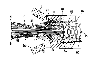
The extrusion head ~ comprises an axially extending
tubular portion 26 which is surrounded in spaced
relationship thereto by a tubular member 27, one end
portion of which screw-threadedly supports an outer member
28 of an corrugate annular extrusion nozzle 24. The
tubular portion 26 carries an inner member 29 of the
extrusion head having a frusto-conical form which
terminates in annular orifice 31 and which communicates
with the annular space 32 between the pipe 27 and the
; 10 p~rtion 26. This annular space 32, in turn, communicates
with the output of the extrusion machine (not shown)
passing the thermoplastic material, such as PVC to the
extrusion nozzle 24.
Downstream of the extrusion nozzle 24 the extrusion head
23 carries, on an extension of tubular portion 26, a
generally cylindrical forming plug 46. The plug 46 is
effective to define the inner wall of pipe formed by
thermoplastic material leaving the extrusion nozzle 24 to
be molded by mold blocks 16. In particular, plug 46 holds
thermoplastic material in troughs 36 of the mold blocks 16
to form annular ribs on the outer surface of the resulting
pipe.
Cooling of plug 46 may be by isentropic expansion of
compressed gas, for example, carbon dioxide, from a source
~ through a supply line 52 which extends through a
central core 53 of tubular portion 26. The supply line 52
leads into a throttle expansion valve 54 which may be of
. any suitable type to allow the gas to expand therethrough
. to cool plug 46. For example, throttle valve 54 may be a
needle valve or a plunger valve or any other suitable type
of valve.
~ `
:
.
- 6 - 13261 18
Adjustment means may be provided to adjust the opening of
valve 54. These adjustment means may be manual screw down
means such as tap 56 for the plunger valve shown in Figure
2. More conveniently however the adjustment means may be
thermostatically controlled in response to the temperature
at the surface of plug 46. Thus, when plug 46 is too cool
for optimum cooling of the inner surface of the pipe, the
adjustment means will tend to close throttle valve 54 and
when the temperature of plug 46 rises the valve 54 will
be correspondingly opened.
~;-`. The interior of the cooling plug ~ should have at least a
channel for expanded cooled gas near its surface or it may
be hollow~ Suitably baffles 57 are arranged to enhance
cooling or, helical coil 60 or other channels may be used.
When the gas to be expanded to cool plug 46 is carbon
dioxide, it is possible to vent the gas directly to the
atmosphere as, for example, at vent 55. It may be
convenient to provide some fan fed chimney or other
venting arrangement to inhibit build up of carbon dioxide
in the work place but such arrangement will be dependent
upon the concentration of carbon dioxide produced or any
regulations concerning its dispersal. In many cases it
may be convenient to use a recirculation system such as
` that illustrated in Figure 2. In this case, expanded gas
from cooling plug 46 is returned through return line 66
through core 53 of tubular portion 26. The expanded gas
is then passed to a compressor 65 before return to a
- holding tank 64. An additional control on the cooling
expansion of gas into plug 46 may be through automatic or
manual adjustment of an exhsust v~lve 61.
.
,
' ~ ' '
- 13261 18
This method also is very advantageous for small diameter
rib or double wall pipe as this system does not require
insulated cooling pipes through the extruder die which
will free~e-up and stop flowing. The duct 52 conveying
the compressed gas to ~he cooling plug may be of the same
temperature of the die, because only at the point of the
gas expansion will it create the temperature drop.
It is conventional to lubricate the surface of at least
cooling plug 46 allow for easy travel of the formed pipe
thereover.
The improvements to the cooling plug makes it more and
more important to also improve the friction co-efficient.
It has previously been suggested to cover a sizing plug
with polytetraflouroethylene as, for example, Teflon
(Trade Mark), chrome plating it, tapering it to a smaller
diameter towards the downstream end so as to avoid
shrinkage of the pipe on to the plug. None of these
methods is wholly satisfactory.
Lubrication may, however, be led in through lubricant
line 62 through core 53 of tubular portion 26.
` Conveniently as shown in Figure 1, the plug 46 is
provided with a porous portion 63, at least at or near
its upstream end but preferably covering the entire
. surface of plug 46 as shown. The porous material may
~ 25 suitably be sintered material allowing seepage of oil or- other lubricant therethrough. Lubricant supply line 62
may open through an annular or other shape accumulator
chamber 48. This lubricant has the additional benefit
that it will enhance the conductivity and therefore
increase the production speed into this porous region 63
which extends around the surface of plug 46 and into the
`:
- 8 - ' 13261 18
-~ body thereof to allow even distribution of lubricant
throughout the region 48 and at the surface thereof.
Figure 5 shows a modification in which two plugs are used.
; Pressurized gas in line 52 is isentropically partially
~ 5 expanded into plug 46 through throttle valve 54. As it
- passes through plug 46, it heats up and may be further
isentropically expanded by throttle valve 59 into plug 47.
Thereafter, it is vented to atmoshpere ~as shown) by valve
61. Alternatively, it may be recycled by a return line
~` 10 and compressor as shown in Figure 2.
,~
: . . : . . : ~:
. ~ . .. .
: :,. ' . . . ~ . ' , :
: ~ . . . .
,: . ' ' ' ' ' . -