Note : Les descriptions sont présentées dans la langue officielle dans laquelle elles ont été soumises.
--` 1 326255
This invention relates to a hydraulic control
valve for controlling the parking brakes of a vehicle
hydraulic braking system having mechanically applied
parking brakes which are released by fluid pressure.
Many medium duty trucks, buses, motorhomes,
etc. are equipped with hydraulic braking systems,,~but
are too large to be parked by using the manually
applied parking mechanism used on smaller vehicles,
such as passenger cars. Accordingly, it has become
common to equip such vehicles with parking actuators
which are mechanically applied by a relatively iarge
spring. When the brake is to be released so~the
vehicle can be moved, hydraulic fluid under pre~fure
opposes the spring, thereby releasing the brake. The
present invention relates to a valve for controlling
the system. A prior art system and valve are discllosed
in U.S. patent 4,072,360. ~1
Such prior art systems use a valve in which
an operator actuated control valve is located onlthe
vehicle dash, and the main system control valve is
located on a different part of the vehicle. The system
control valve includes a valve member which is actuated
by hydraulic pressure supplied from the operator
actuated control valve. Accordingly, the valves taken
together require nine or more separate hydraulic
connections. The valve according to the present
invention is directly actuated by the vehicle operator
to eliminate all but three of these connections, to
thereby provide better performance, and better
reliability.
Generally speaking, the present invention may
be considered to provide a control valve for
controlling the parking brakes of a vehicle braking
system having a source of fluid pressure, a reservoir,
''~; "
- ~ i
~:
-
~: ,
~` 1 326255
- la -
and mechanically applied parking brakes which are
released by fluid pressure, the control valve
comprising a housing having an inlet port communicated
to a fluid pressure source, a return port communicated
to the reservoir, and a delivery port communicated to
the parking brakes, a diverter assembly within the
housing responsive to fluid communication through the
inlet port to establish a fluid pressure level
communicated through the delivery port to the parking
brakes for releasing the latter, a diverter passage
communicating the inlet port with the diverter
assembly, a system bypass passage communicating the
inlet port with the return port bypassing the diverter
~ assembly, and valve means in the housing movable from a
first position closing the diverter passage and opening
the bypass passage to a second condition closing the
bypass passage and opening the diverter passage.
This and other advantages of the present
invention will become apparent from the following
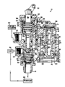
~ 20 specification, with reference to the accompanying
S drawing, the sole figure of which is a cross-sectional
view of a hydraulic control valve made pursuant to the
teachings of the present invention.
. Referring now to the drawing, the hydraulic
control valve generally indicated by the numeral 10
includes a housing 12 having an inlet or supply port
14, a return or drain port 16, and a delivery port 18.
The
sd/sp
fJ
, ,, , : ~ . :
- 2 _ 1 32625
delivery port 18 is communicated with the vehicle spring
apply hydraulic release parking brake chambers generally
indicated by the numeral 20. Parking brake chambers 20
are conventional, and, since they form no part of the
05 present invention, will not be disclosed in detail. Inlet
port 14 is connected to the outlet of a conventional
hydraulic pump 22, the inlet of which is connected to a
reservoir 2g. The return or drain port 16 is communicated
to the inlet of the reservoir 24.
Housing 12 defines a bore 26 therewithin which
slidably receives an elongated spool valve assembly 28.
Spool valve assembly 28 includes a spool 29 and a portion
30 which e~tends through the end of bore 26 and which
engages a mechanical actuator 32. Portion 30 is connected
to spool 29 through a lost motion spring loaded connection
comprising a spring 34 which urges circumferentially
extending member 36 against stop ring 38. The mechanical
actuator 32 may be connected to a standard push-pull knob
on the vehicle dashboard, or may be connected to the
vehicle automatic transmission lever so that the spool
valve assembly 28 is automatically actuated when the
vehicle operator moves the automatic transmission into the
"parked" condition. The mechanical actuator 32 may also
be connected to a solenoid actuator.
A first set of circumferentially extending,
cooperating valve elements 40, 42 are defined on the wall
of the bore 26 and on the spool 29 respectively. The
valve elements 40, 42 cooperate to control communication
between the delivery port 18 and a circumferentially
extending chamber 44 defined between the spool 29 and the
wall of the bore 26. A second set of cooperating valve
elements 46, 48 are defined respectively on the spool 29
and on an annular member 50 which is slidably mounted
within the bore 26. The annular member 50 is urged into
the position illustrated in the drawing by a spring 52.
It will be noted that a limited degree of sliding
movement, indicated by the distance D, is allowed the
annular member 50. A spring 54 urges the spool valve
assembly 28 into the
~ 1 326255
- 3 -
position illustrated in the drawing. The limited degree
; of axial movement permitted the annular member 50 permits
the valve seat 46 to sealing engage the valve seat 48,
while simultaneously permitting the valve members 40, 42
05 to engage one another. The valve elements 46, 48 control
; communication between the inlet port 14 and an annular
chamber 56 defined between the spool 29 and the wall of
the bore 26 and between the inlet port 14 and the return
or drain port 16.
Valve 10 further includes a diverter assembly
î generally indicated by the numeral 58. Diverter assembly
58 includes a differential area piston assembly 60. One
end 62 of piston 60 is slidably received in bore 64
defined within the housing 12 and cooperates with the end
thereof to define a chamber 66 which is vented to the
return or drain port 16 through passage 68, drain chamber
70, and an opening 72 in the annular member 50. The
opposite end 74 of piston 60 is slidably received in bore
~ 76 defined within the housing 12. Fluid pressure
r' 20 communicated into annular chamber 78 through a diverter
passage 80 from annular chamber 56 acts on projecting
~ portion 82 of the piston 60 to oppose the force exerted on
i~ end 74 by fluid pressure in chamber 84 defined between the
end 74 of the piston 60 and the corresponding end of the
housing 12. Fluid pressure in chamber 84 communicates
with the delivery port 18 through delivery passage 86. A
relief valve 88 communicates chamber 84 with annular
chamber 44 when the pressure level in chamber 84 (and
therefore at delivery port 18) exceeds a predetermined
' 30 pressure level.
Fluid communicates into the chamber 84 from
chamber 78 through a passage 90 defined within the piston
60. An inlet check valve 92 carried by the piston 60
permits communication from chamber 78 into chamber 84, but
prevents communication the reverse direction. When check
valve 92 is open, fluid communicates through passages
defined between circumferentially spaced splines 94 on the
check valve 92. A spring 96 yieldably urges check valve
1 326255
-- 4 ~
92 into sealing engagement with the valve seat 98 defined
on the passage 90.
A spring 100 yieldably urges the piston 60
upwardly viewing the Figure, thereby yieldably urging
05 valve member 102 on the piston 60 into engagement with
valve member 104 on the housing 12. As will be described
hereinafter, equal pressures acting in the chamber 78 and
84, due to the differential in the effective areas of the
piston 60 exposed to these pressures, will create a force
differential across the piston 60 sufficient to overcome
j the spring 100 at a predetermined pressure level, thereby
opening the valve members 102, 104. A diverter bypass
passage 106 communicates with annular chamber 108 with a
drain passage 110, which communicates with drain chamber
70 which, as discussed hereinabove, communicates with
drain return port 16 through the opening 72. Drain
passage 110 includes a branch 112 which communicates with
annular chamber 44. A check valve 114 is provided in the
branch 112 to prevent fluid from diverter bypass passage
106 from communicating into the annular chamber 44, but
permitting fluid pressure in annular chamber 44 to drain
into the drain chamber 70.
In operation, the valve 10 as illustrated in the
Figure with the components thereof in the positions which
they assume in which the vehicle is parked. In this
condition, parking brake chambers 20 are vented through
delivery port 18 to return port 16 through the drain
passage 110 and drain cavity 70. Since the pressure level
at delivery port 18 is then at substantially the
atmospheric pressure of the reservoir, the spring parking
brake actuator effects a mechanical applied parking brake
application. Although pump 22 is running at all times
that the vehicle engine is running, fluid communicated
into inlet port 14 is communicated directly to the drain
or return port 16, and therefore back to the reservoir
24. Communication between the inlet port 14 and annular
chamber 56 is shut off.
. . . .
1 326255
-- 5 --
When the vehicle is to be moved, mechanical
actuator 32 is operated to force the spool valve assembly
28 downwardly viewing the Figure, to bring the valve
elements 40, 42 into engagement with one another, thereby
05 cuttin~ off cor~munication between the parking brake
chambers 20 and the drain passage 110. At the same time,
valve element 46 moves into engagement with valve element
48, to thereby cut off communication between inlet port 14
and drain or return port 16, and to simultaneously
initiate communication between the inlet port 14 and
annular chamber 56. Fluid communicated to inlet port 14
communicates into chamber 56, and thereafter communicates
into chamber 78 through diverter passage 80. Fluid in
chamber 78 communicates into chamber 84 through passage 90
and the check valve 92. As discussed hereinabove,
- although the pressures in chamber 78 and 84 will be
substantially equal due to communication through the
passage 90, the force acting on the piston 60 will be
unequal due to the differential in the effective areas
exposed to the fluid pressure level in chamber 78 and
chamber 84.
Fluid communicates from chamber 84 to the brake
chambers 20 through passage 86 and delivery port 18. As
fluid continues to communicate into chamber 84, the
pressure in chambers 84 and 78 gradually increases, since
additional fluid is continually being communicated into
the chamber 78. This increase in fluid pressure overcomes
the mechanical or spring forces used to apply the parking
brake chambers 20, thereby releasing the parking brakes
and permitting the vehicle to be moved. When a
predetermined pressure level is attained in the chambers
78 and 84, the force of spring 100 acting on piston 60 is
overcome due to the aforementioned force differential.
When this occurs, valve elements 102, 104 open to permit
fluid to bypass the piston 60 through diverter bypass
passage 106 into the drain passage 110. Accordingly,
fluid pressure in chamber 84 is maintained at a
predetermined level. Of course, should the pressure
- ; 1 326255
: - 6 -
levels in chambers 78 or 84 be reduced, due to leakage,
- change in temperature, or for any other reason, a force
differential is created on piston 60 causing the valve
elements 102, 104 to reclose, thereby diverting additional
05 fluid into chamber 84 to increase the pressure level
` therein. If the pressure level in the parking brake
chambers 20 and chamber 84 increases above the working
~ level due to, for example, changes in ambient temperature
causing expansion of the hydraulic fluid, excessive
i 10 pressure above a predetermined pressure level is vented
through relief valve 88 into annular chamber 44, and from
' there through drain passage 110 and drain chamber 70 to
the return or drain port 16.
When the vehicle is parked and the parking brakes
15 are to be applied, the spool valve assembly 28 is mo~ved to
. the position illustrated in the drawing, thereby cutting
off communication into the chamber 78 and permitting
/ delivery port 18 to be vented into annular chamber 44 and
; drain passage 110 into drain chamber 70, thereby
, 20 permitting the aforementioned spring brake actuator to be
r applied.
-
~ 25
" .
"
~ . . ,,, . ~
~' , . - , :
-