Note : Les descriptions sont présentées dans la langue officielle dans laquelle elles ont été soumises.
~ 32~73
VhHICLl~ DC)OR--TO--DOOR SUNROOF ASSEMBLY
TE:CHNICAL FIELD
This invention relates to a sunroof assembly
for a vehicle body.
BACKGROUND ART
Vehicle body sunroof assemblies have been
used for quite some time to provide partial opening of
vehicle body roofs in order to increase ventilation and
to also provide the roof with a somewhat convertible-
like capability of opening the vehicle occupantcompartment. With some sunroof assemblies, the sunroof
has a front edgo that is secured to the roof and a rear
edge that is movable upwardly from a closed position to
an open position under the control of a latch mechan-
ism. With other sunroof assemblies, the ~unroof ismounted for longitudinal movement between a forward
position closing the roof opening and a rearwardly
retracted position below the roof to the rear of the
roof opening such that the roof opening is partially
opened to the environment. Examples of these two types
of sunroof assemblies are disclosed by United States
Patents: 4jO05,901; 4,038,910; 4,085,965; 4,103,962;
4,126,352; 4,350,385; 4,403,805; 4,523,785; and
4,541,665.
In some roof constructions, there is
insufficient room for a sunroof assembly of the
rearwardly retractably type to have its sunroof stored
belo~ the roof in the rearwardly retracted position.
To overcome this problem, it has previously been
... .
', ~
13~87~
proposed to have the sunroof stored externally at a
location above the roof in the rearwardly retracted
position. Examples of such externally retracted
sunroof assemblies are disclosed by United states
Patents: 3,993,348; 4,005,900; 4,043,590; 4,407,541;
4,426,112; 4,463,983; and 4,475,767.
Vehicle sunroof assemblies as described above
are conventionally mounted on a vehicle roof by cutting
an opening through the outer roof panel over the front
seat area that is selectively opened and closed by the
sunroof. The lateral dimension of such sunroof
assemblies is limited by the fact that the roof opening
cut has to be located at each lateral side inboard from
the adjacent side rail that defines the edge of the
roof. Such side rails are conventionally defined by
the adjacent side edge of the outer roof panel and by
an inner rail that cooperates with the side edge to
provide a hollow side rail for rigidifying the roof in
order to provide the vehicle with structural integrity.
The limitation on lateral width of sunroof assemblies
is a particular problem with a recently introduced type
of vehicle body wherein side door window frames have
outer members that continue the contour of the outer
roof panels at their side edges rather than being
2S located below drip rails at the side edges of the roof.
With this type of vehicle body construction, the side
rails are located farther inboard than with the drip
rail type of roof construction and there is thus less
lateral space for the sunroof assembly to by mounted
within an opening through the outer roof panel. An
externally retractable sunroof assembly having a
sunroof panel that extends between the doors is
disclosed by United States Patent 4,695,090.
.
.: ~
, . i . .
.
1326873
--3--
In order to overcome storage problems
associated with single panel vehicle sunroof assemblies,
prior vehicles have included sunroof assemblies with
multiple panels. See, for example, United states
Patents: 1,826,871; 1,839,727; 2,115,432; 2,861,836;
4,157,845; and 4,474,405. However, such multiple panel
sunroof assemblies require seals at the junctions of the
panel in order to seal the vehicle occupant compartment
from the environment.
Other vehicle body tops that can be opened in
a convertible like manner have included a flexible cover
associated with one or more panels or bows in order to
provide sealing in the closed position. See, for
example, United states Patents: 2,947,570; 3,658,378;
and 3,720,440.
~SCLOSURE OF INVENTION
An ob~ect of the present invention i5 to
provide an improved vehicle sunroof assembly that
extends between the upper edges of a~sociated side doors
and has multiple panels and a sheet-like cover that
cooperate to selectively provide either closing of a
roof opening between the side doors or opening thereof
with the panels stored in a stacked relationship and the
sheet-like cover folded between the panels.
In accordance with one broad objective of the
invention, a vehicle body in which the sunroof assembly
is incorporated includes an outer roof panel having side
edges and also has inner rails that cooperate with the
side edges of the outer roof panel to provide a pair of
hollow side rails. The vehicle body also includes side
doors having upper edges located adjacent the side edges
of the outer roof panel. The sunroof assembly includes
`
.
. .
- . . : . ~
.
~ .
,
1~2687~
-4-
a roof opening formed in the outer roof panel with
forward and rearward edqes and with side edges exposing
the interior of the side rails of the roof. A pair of
tracks of the sunroof assembly are also provided with
one of the tracks mounted within one of the side rails
and with the other track mounted within the other side
rail. Each track includes a plurality of inclined ramps
and horizontally extending portions connecting the
ramps. Each ramp extends downwardly in a forward
direction. The sunroof assembly also has a sunroof
including a plurality of panels having elongated shapes
extending laterally with respect to the vehicle body.
Each panel has opposite ends one of which has a front
portion mounted by one track in one of the side rails
and the other of which has a front portion mounted by
the other track in the other side rail. These tracks
cooperate to support the panels for forward and rearward
movement with respect to the vehicle body. The panel
ends are located generally adjacent the upper edges of
the closed side doors to provide a generally continuous
door-to-door construction. The sunroof also includes a
flexible sheet-like cover that extends between the
panels and has connections to the panels. These
connections to adjacent panels are spaced along the
cover with greater spacings than the front-to-rear
dimensions of the panels. The sunroof is movable
between a closed position with respect to the roof
opening where the panels are spaced from each other with
the cover extending therebetween and an open position
where the panels are positioned adjacent the rear edge
of the roof opening in a partially overlapping
relationship with the cover stored therebetween in a
folded condition.
Each track in the preferred construction of
the sunroof assembly has inboard and outboard flanges
'
.
. .
. .
1326873
secured to the associated roof side rail. A track
portion of each track is located laterally intermediate
its inboard and outboard flanges. This track portion of
each track preferably projects upwardly and has a track
groove. Each opposite end of each sunroof panel has a
support element of the support thereof received by the
track portion groove of the associated track to provide
mounting thereof on the track.
In the preferred sunroof assembly
construction, each track portion has its groove provided
with a horizontally opening configuration and each
sunroof panel end has a downwardly projecting front
support on which its support element is mounted. The
support elements of the sunroof panels are preferably
rollers that are received within the groove of the
associated track portion in order to facilitate the
panel movement. The groove of each track portion most
preferably opens in an inboard direction with respect to
the vehicle body with the associated panel support
located inboard therefrom and supporting the roller that
is received within the track groove. Each track also
preferably includes an upwardly projecting guide that
opposes the horizontally opening groove with the
downwardly projecting front portion therebetween in a
captured relationship.
,
In its preferred construction, the sunroof
assembly also has each track provided with at least one
water outlet through which rain and other moisture
accumulation can drain. Each track preferably has at
least one end at which its water outlet is located and
most preferably has both front and rear ends that each
have an associated water outlet for drainage of
moisture.
'
.. . . . . . . . .
1326~73
In accordance with another broad objective of
the invention, a vehicle body including an outer roof
panel having side edges and also having inner rails that
cooperate with the side edges of the outer roof panel to
provide a pair of hollow side rails, and side doors
having upper edges located adjacent the side edges of
the outer roof panel, a sunroof assembly of the
invention comprises: a roof opening in the outer roof
panel; said roof opening having forward and rearward
edges and having side edges exposing the interior of the
side rails of the roof; a pair of tracks each of which
includes a plurality of inclined ramps and horizontally
extending portions connecting the ramps; each ramp
extending downwardly in a forward direction; one of the
tracks being mounted within one of the side rails and
the other track being mounted within the other side
rail; each track including a track portion having a
groove; a sunroof including a plurality of panels having
elongated shapes extending laterally with respect to the
vehicle body; each panel having opposite ends one of
which has a front support having a support element
received by the track portion groove of one track in one
of the side rails and the other of which has a front
support having a support element received by the track
portion groove of the other track in the other side
rail; said tracks cooperating with the support elements
to support the panels for forward and rearward movement
with respect to the vehicle body; said panel ends being
located generally adjacent the upper edges of the closed
side doors to provide a generally continuous door-to-
door construction; said sunroof also including a
flexible sheet-like cover that extends between the
panels and has connections to the panels; said
connections to adjacent panels being spaced along the
cover with greater spacings than the front-to-rear
dimensions of the panels; and said sunroof being movable
,
: , ~ : - -: .
~: ' '
1~26873
~ -6a-
between a closed position with respect to the roof
opening where the panels are spaced from each other with
the cover extending therebetween and an open position
where the panels are positioned adjacent the rear edge
of the roof opening in a partially overlapping
relationship with the cover stored therebetween in a
folded condition.
In accordance with another broad objective of
the invention, a vehicle body including an outer roof
panel having side edges and also having inner rails that
cooperate with the side edges of the outer roof panel to
provide a pair of hollow side rails, and side doors
having upper edges located adjacent the side edges of
the outer roof panel, a sunroof assembly of the
invention comprises: a roof opening in the outer roof
panel; said roof opening having forward and rearward
edge6 and having side edges exposing the interior of the
side rails of the roof; a pair of tracks each o~ which
includes a plurality of inclined ramps and horizontally
extending portions connecting the ramps; each ramp
extending downwardly in a forward direction; one of the
tracks being mounted within one of the side rails and
the other track being mounted within the other side
rail; a sunroof including a plurality of panels having
elongated shapes with front and rear sides extending
laterally with respect to the vehicle body; each panel
having opposite ends one of which has a downwardly
projecting front.support mounted by one track in one of
the side rails and the other of which has a downwardly
projecting front support mounted by the other track in
the other side rail; said traaks cooperating to support
the panels for forward and rearward movement with
respect to the vehicle body; said panel ends being
located generally adjacent the upper edges of the closed
side doors to provide a generally continuous door-to-
. ~ ,~ ,:
,
1326873
-6b-
door construction; said sunroof also including a
flexible sheet-like cover that extends between the
panels and has connections to the rear sides of the
panels; said connections to adjacent panels being spaced
along the cover with greater spacings than the front-to-
rear dimensions of the panels; and said sunroof being
movable between a closed position with respect to the
roof opening where the panels are spaced from each other
with the cover extending therebetween and an open
position where the panels are positioned adjacent the
rear edge of the roof opening in a partially overlapping
relationship with the cover stored therebetween in a
folded condition.
In accordance with another broad objective of
the invention, a vehicle body including an outer roof
panel having side edges and also having inner rails that
cooperate with the side edges of the outer roof panel to
provide a pair of hollow side rails, and side doors
having upper edges located adjacent the side edges of
the outer roof panel, a qunroof assembly of the
invention comprises: a roof opening in the outer roof
panel; said roof opening having forward and rearward
edges and having side edges exposing the interior of the
side rails of the roof; a pair of tracks each of which
includes a plurality of inclined ramps and horizontally
extending portions connecting the ramps; each ramp
extending downwardly in a forward direction; one of the
tracks being mounted within one of the side rails and
the other track being mounted within the other side
rail; each track having inboard and outboard flanges
mounted on the associated side rail and having an
upwardly projecting track portion located between its
flanges; the track portion of each track having a track
groove that opens in an inboard direction; a sunroof
including a plurality of panels having elongated shapes
1~ ` I
'
~ .
-` 13~6873
-6c-
with front and rear sides extending laterally with respect to the -
vehicle body; each panel having opposite ends one of which has a
downwardly projecting front support including a support element
received within the track portion groove of one track in one of
the side rails and the other of which has a downwardly projecting
front support including a support element received within the
track portion groove of the other track in the other side rail;
said tracks cooperating to support the panels for forward and
rearward movement with respect to the vehicle body; said panel
ends being located generally adjacent the upper edges of the
closed side doors to provide a generally continuous door-to-door
construction; said sunroof also including a flexible sheet-like
cover that extends between the panels and has connections to the
rear sides of the panels; said connections to adjacent panels
being spaced along the cover with greater spacings than the
front-to-rear dimensions of the panels; and said sunroof being
movable between a closed position with respect to the roof opening
where the panels are spaced from each other with the cover
extending therebetween and an open position where the panels are
positioned adjacent the rear edge of the roof opening in a
partially overlapping relationship with the cover stored
therebetween in a folded condition.
The objects, features, and advantages of the present
invention are readily apparent from the following detailed
description of the best mode for carrying out the invention when
taken in connection with the accompanying drawings.
.~
' ' . : ~ :' . '
132687~
--7--
BRIEF DESCRIPTION OF DRAWINGS
FIGURE 1 is a perspective view of a vehicle
whose vehicle body includes a door-to-door sunroof
assembly constructed in accordance with the present
invention and is illustrated with a sunroof thereof in
a closed position;
FIGURE 2 is a partial perspective view of the
vehicle body showing the sunroof in a partially open
position;
FIGURE 3 is an elevational view taken
laterally in section through a vehicle body prior to
cutting of a roof or installation of the sunroof
assembly of the present invention;
FIGURE 4 is a sectional view similar to
Figure 3 taken after the installation o~ the sunroo~
assembly;
FIGURE 5 is a longitudinal view taken
partially in section along the direction of line 5-5 in
Figure 1 to illustrate the sunroof assembly in its
closed position;
FIGURE 6 is a partial sectional view taken
along the direction of line 6-6 in Figure 2 and
illustrates the sunroof assembly in its partially open
position; and
FIGURE 7 is a partial sectional view taken in
the same direction as Figures 5 and 6 but illustrating
the sunroof assembly in its open position.
.~ - .~ . -
-
1326873
--8--
BEST MODE FOR CARRYING OUT THE INVENTION
With reference to Figures 1 and 2, a vehicle
generally indicated by 10 is disclosed as including a
vehicle body 12 whose roof 14 is conventionally located
to the rear of the windshield 16 and forward of the
rear window 18 in a conventional manner. The wind-
shield 16 shown in Figure 2 is located to the rear of
the front engine compartment lid 20 shown in Figure 1,
and the rear window 18 is located forwardly from the
rear storage compartment lid 22 in a conventional
fashion. At each lateral side of the vehicle, the
vehicle body 12 includes an associated side door 24
having a window 26 that is movable vertically between
open and closed positions in a conventional manner.
Each of the side doors 24 is disclosed as having a
window frame 28 that extends around the front, top, and
rear sides of the window 26 in the closed position
illustrated. A sunroof assembly 30 according to the
present invention is illustrated in Figure 1 in a
closed position and in Figure 2 in a partially open
position as is hereinafter more fully described. It
should be appreciated that this sunroof assembly 30 can
also be utilized with a vehicle body whose side doors
include frameless windows as well as the framed windows
shown. However, the invention has particular utility
with framed side door windows for reasons hereinafter
described.
With reference to Figure 3, the vehicle body
12 in which the sunroof assembly is installed has its
roof 14 provided by an outer roof panel 32 having side
edges 34 located adjacent the upper door edges provided
by the window frames 28. A pair of inner rails 36 of
- . . .
i ~ :
13~6873
g
the roof 14 cooperate with the roof panel side edges 34
to provide hollow side rails 38 at each lateral side of
the roof. Each inner side rail 36 includes inboard and
outbo~rd rail members 40 and 42 which have a flanged
connection 44 secured by spot welding and covered by a
trim strip 46. The outboard side rail 42 also has a
flanged connection 48 that is secured by a rivet 50 and
which supports a seal 52 that is engaged by the upper
side door edge provided by the window frame 28.
Between the side doors, the roof 14 also includes an
inner headliner 54 that is secured by the trim strips
46 and other conventional attachments to the roof 14.
Sunroof assembly 30 illustrated in Figures 1
and 2 is installed by initially providing an opening 56
in the outer roof panel 32. This opening 56 is
provided by cutting the roof panel 32 laterally to
provide front and rear edges 58 and 60 of the opening
and, as shown in Figure 4, by completely removing the
roof panel between the rail members 42 to expose the
interior of the side rails 38.
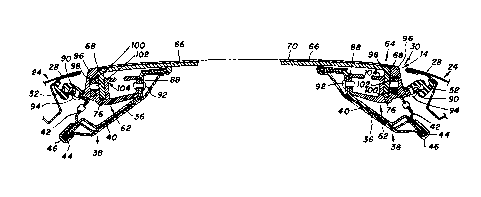
As shown by continuing reference to Figure 4,
the sunroof assembly 30 included a pair of tracks 62
one of which is mounted within one of the side rails 3~
and the other of which is mounted within the other side
rail 38 as is hereinafter more fully described.
Sunroof assembly 30 includes a sunroof 64
having a plurality of panels 66 with elongated shapes
extending laterally with respect to the vehicle body as
best illustrated in Figures 1 and 2. As shown in
Figure 4, each panel 66 has opposite ends 68 one of
which is mounted by one track 62 in one of the side
.
... . . ~ .
, . ' . ~ ~; . . . :
. : . .: - .
--" 1326873
--10--
rails 38 and the other of which is mounted by the other
track 62 in the other side rail 38. The tracks 62
cooperate to mount the panels 66 for forward and
rearward movement with respect to the vehicle body.
The opposite panel ends 68 are juxtaposed, i.e.
positioned immediately adjacent, the upper side door
edges provided by the window frames 28 of the closed
side doors 24 to thereby provide a door-to-door
construction. The sunroof assembly has particular
utility with the type of vehicle illustrated where the
door window frames 28 continue the contour of the roof
14, as shown in Figures 3 and 4, since the side rails
38 of this type of vehicle extend in an inboard
direction a greater extent than with other type
vehicles and conventional sunroofs, which must be
located between the side rails, thus cannot have a very
great lateral dimension in comparison to the door-to-
door construction. However, it should be appreciated
that the sunroof assembly of this invention can also be
utilized with other types of vehicles, such as vehicles
with unframed side door windows, even though it does
have particular utility with vehicles having side door
window frames that continue the roof contour as
previously mentioned.
As shown in Figures 4-7, the sunroof 64 also
includes a flexible sheet-like cover 70 that extends
between the panel 66 and has connections 72 to the
panel. Cover 70 is most preferably made from a resin
impregnated cloth so as to have strength as well as
being resistant to deterioration from moisture and the
sun. Connections 72 are most preferably provided by an
adhesive bond between the lower surface of the cover 70
and the rearward extremities of the panels 66. These
..
'' : .
` 132687~
--11--
connections are spaced along the cover with greater
spacings than the front-to-rear dimensions of the
panels as best shown in Figure 5. Sunroof 64 is
movable either manually or by a power actuator between
the closed position of Figure 5, the partially open
position of Figure 6, and the fully open position of
Figure 7. In the closed position of Figure 5, the
panels 66 are spaced from each other with the cover 70
extending therebetween to define the contour of the
roof. In the open position of Figure 7, the sunroof
panels 66 are positioned adjacent the rear edge 56 of
the roof opening in an overlapping relationship with
the cover 70 stored therebetween in a folded relation-
ship.
As illustrated in Figure 7, the sunroof 64
preferably has its panels 66 overlapping each other
less than completely in the open position with respect
to the roof opening 56. This partial overlapping is
accomplished by providing the opposite ends 68 of the
sunroof panel 66 each with a front side 74 having a
front support 76 mounted by the associated track 62
within the ad~acent roof side rail. Each sunroof panel
66 also includes a rear side 78 that is located
rearwardly of its track mounted front supports 76. In
the stored position of Figure 7, the folded cover 70
extends from the connection 72 at the rear side 78 of
each panel forwardly below that panel and is then
folded downwardly and back rearwardly so as to extend
to the connection 72 at the rear side 78 of the next
rearward panel. Upon forward movement of the sunroof
64 from the stored open position of Figure 7 through
the partially closed position of Figure 6 to the fully
closed position of Figure 5, the cover 70 unfolds as
132687~
-12-
the panels 66 move away from each other to the spaced
relationship where the cover fully closes the roof
opening 56. In this fully closed position, a seal 80
on the front side 74 of the forwardmost panel 66
engages the windshield header 82 to provide sealing of
the closure at the upper extremity of the windshield
16.
As best illustrated in Figure 7, each track
62 includes a plurality of inclined ramps 84 and
horizontally extending portions 86 connecting the
ramps. The number of ramps 84 of each track 62 is one
less than the number of sunroof panels 66. Each of the
ramps 84 extends downwardly in a forward direction such
that the rear side 78 of each panel 66 is moved
upwardly as the front support 76 thereof moves along
the ramps to thereby facilitate the overlapping storage
of the sunroof panels in the open position as well as
facilitating the folding of the cover 70 between the
panels as shown in Figure 6.
As illustrated in Figure 4, each track 62 has
inboard and outboard flanges 88 and 90 secured to the
associated roof side rail 38 preferably by rivets 92
and 94O Each track 62 also includes a track portion 96
located laterally intermediate its inboard and outboard
flanges 88 and 90 to provide support for the opposite
ends 68 of the sunroof panels 66. The track portion 96
of each track 62 preferably projects upwardly and has a
track groove 98. Each opposite end 68 of each sunroof
panel 62 has at least one support element 100 received
by the track portion groove 98 of the associated track
62 to provide mounting thereof on the track. As
illustrated, each track portion 96 has its groove 98
~, . .
.
132687~
-13-
provided with a horizontally opening configuration.
Each sunroof panel end 68 preferably has its front
support 76 provided with a downwardly projecting
construction on which its support element 98 is
mounted. As illustrated, the support elements 100 are
rollers that are supported by pins 102 and each panel
end 68 has two of such roller support elements lOo
supported by a pair of the pins 102. It should be
appreciated that it is also possible to utilize slides
instead of the rollers even though it is preferable to
utilize the rollers in order to reduce friction and the
consequent total effort required to move the sunroof
between the closed and open positions.
As shown by continuing reference to Figure 4,
the groove 98 of each track 62 opens in an inboard
direction with respect to the vehicle body with each
pin 102 extending generally horizontally into the
groove to support its roller element 100. Each track
62 also includes an upwardly projecting guide 104 that
opposes the horizontally opening groove 98 with the
downwardly pro~ecting front support 76 of the asso-
ciated panel end therebetween in a captured relation-
ship.
As shown in Figures 5-7, each track 62
includes at least one water outlet 106 and preferably
has at least one end 108 at which the outlet is
located. Most preferably, each track 62 has front and
rear outlets 106 and 110 respectively located at front
and rear ends 108 and 112 of the track.
~ 1326873
While the best mode for carrying out the
invention has been described in detail, those familiar
with the art to which this invention relates will
recognize various alternative designs and embodiments
for carrying out the invention as defined by the
following claims.
..