Sélection de la langue

Search

Sommaire du brevet 1327035 

Énoncé de désistement de responsabilité concernant l'information provenant de tiers

Une partie des informations de ce site Web a été fournie par des sources externes. Le gouvernement du Canada n'assume aucune responsabilité concernant la précision, l'actualité ou la fiabilité des informations fournies par les sources externes. Les utilisateurs qui désirent employer cette information devraient consulter directement la source des informations. Le contenu fourni par les sources externes n'est pas assujetti aux exigences sur les langues officielles, la protection des renseignements personnels et l'accessibilité.

Disponibilité de l'Abrégé et des Revendications

L'apparition de différences dans le texte et l'image des Revendications et de l'Abrégé dépend du moment auquel le document est publié. Les textes des Revendications et de l'Abrégé sont affichés :

  • lorsque la demande peut être examinée par le public;
  • lorsque le brevet est émis (délivrance).
(12) Brevet: (11) CA 1327035
(21) Numéro de la demande: 1327035
(54) Titre français: OUTIL DE CAROTTAGE
(54) Titre anglais: CORE DRILLING TOOL
Statut: Périmé et au-delà du délai pour l’annulation
Données bibliographiques
(51) Classification internationale des brevets (CIB):
  • E21B 25/02 (2006.01)
  • E21B 25/16 (2006.01)
(72) Inventeurs :
  • JURGENS, RAINER (Allemagne)
  • SPERBER, AXEL (Allemagne)
(73) Titulaires :
  • BAKER HUGHES INCORPORATED
(71) Demandeurs :
  • BAKER HUGHES INCORPORATED (Etats-Unis d'Amérique)
(74) Agent: GOWLING WLG (CANADA) LLP
(74) Co-agent:
(45) Délivré: 1994-02-15
(22) Date de dépôt: 1989-04-24
Licence disponible: S.O.
Cédé au domaine public: S.O.
(25) Langue des documents déposés: Anglais

Traité de coopération en matière de brevets (PCT): Non

(30) Données de priorité de la demande:
Numéro de la demande Pays / territoire Date
P3813508.6 (Allemagne) 1988-04-22

Abrégés

Abrégé anglais


ABSTRACT
Core drilling tool for drilling rock in
underground soil formations with an outside pipe that can
be connected by means of connecting devices at its upper
end to the lower end of a drill column that can be set
rotation by means of a drive and can be connected at its
lower end to a core drilling crown, and with an inside
pipe that forms a separate component that can be conveyed
to the surface and a supporting part which is supported in
the outside pipe and is corotational with the latter as
well as a core pipe part suspended on the carrying part by
means of a bearing so it cannot twist relative to the
outside pipe and can receive a core cut by the drilling
process, wherein the core pipe part comprises a
measurement unit located in its upper area for on-site
acquisition, processing and storage of data that form
parameters for the borehole, the drilling core and/or
drilling process.

Revendications

Note : Les revendications sont présentées dans la langue officielle dans laquelle elles ont été soumises.


CLAIMS
1. Core drilling tool for drilling a borehole in underground soil formations
with an outside pipe including an upper end and a lower end that can be
connected by means of connecting devices at its upper end to the lower end
of a drill column that can be rotated by means of a drive and can be connected
at its lower end to a core drilling crown, and with an inside pipe that forms a
separate component that can be conveyed to the surface and a supporting part
which is supported in the outside pipe and is co-rotational with the latter as
well as a core pipe part suspended on the supporting part by means of a
bearing so it will not twist relative to the outside pipe and can receive a corecut by the drilling process, wherein the core pipe part comprises a
measurement unit located in its upper area for onsite acquisition, processing
and storage of data that form parameters for one or more of the borehole, the
cut core, or the drilling process, and a traction device which can be connected
to the inside pipe by means of a gripping device, said traction device
comprising a line for transmission of measurement data to the surface.
2. Tool according to claim 1, wherein said measurement unit has a
measured value pickup for acquisition of such data as one or more of the
borehole temperature, slope, azumuth, or drilling progress.
3. Tool according to claim 1, wherein said measurement unit includes
measured value pickup for acquisition of data on one or more of the drilling
pressure, torque, or rotational speed of the outside housing.
4. Tool according to claim 1, characterized in that the measurement unit
includes measured value pickup for acquisition of information regarding the
properties of the rocks of the soil formation.
5. Tool according to claim 1, wherein said measurement unit includes
measured value pickup for acquisition of data on one or more of the core gain,
progress, jamming, orientation, or its properties.

6. Tool according to claim 1, wherein said measurement unit can be
retracted mechanically together with the inside pipe or can be conveyed to the
surface hydraulically be means of drilling mud.
7. Tool according to claim 1, characterized in that the measurement unit
comprises rechargeable electric batteries for its power supply.
8. Tool according to claim 1, wherein said measurement unit is provided
with an electric generator that can be driven with drilling mud for its power
supply.
9. Tool according to claim 1, wherein said measurement unit can be
gripped underground by means of a separate gripping tool, can be detached
from the core pipe part and conveyed to the surface separately.
10. Core drilling tool for drilling a borehole in underground soil
formations with an outside pipe including an upper end and a lower end that
can be connected by means of connecting devices at its upper end to the
lower end of a drill column that can be rotated by means of a drive and can be
connected at its lower end to a core drilling crown, and with an inside pipe that
forms a separate component that can be conveyed to the surface and a
supporting part which is supported in the outside pipe and is co-rational with
the latter as wall as a core pipe part suspended on the supporting part by
means of a bearing so it will not twist relative to the outside pipe and can
receive a core cut by the drilling process, wherein the core pipe part comprisesa measurement unit located in its upper area for on-site acquisition, processingand storage of data that form parameters for one or more of the borehole, the
cut core, or the drilling process, wherein said measurement unit has at least
one area shielded by a heat protection device to hold heat-sensitive
components.
11. Core drilling tool for drilling a borehole in underground soil
formations with an outside pipe including an upper end and a lower end that
can be connected by means of connecting devices at its upper end to the
lower end of a drill column that can be rotated by means of a drive and can be

connected at its lower end to a core drilling crown, and with an inside pipe that
forms a separate component that can be conveyed to the surface and a
supporting part which is supported in the outside pipe and is co-rational with
the latter as well as a core pipe part suspended on the supporting part by
means of a bearing so it will not twist relative to the outside pipe and can
receive a core cut by the drilling process, wherein the core pipe part comprisesa measurement unit including heat-sensitive components located in its upper
area for on-site acquisition, processing and storage of date that form
parameters for one or more of the borehole, the core, or the drilling process,
wherein said heat-sensitive components of said measurement unit are provided
with their own heat protection devices.

Description

Note : Les descriptions sont présentées dans la langue officielle dans laquelle elles ont été soumises.


132~Q3S
~BACKGR~UN~ O~ THE rI~
~ hi~ invention concqrns I ~enerally, improvement~ to a
~o~e drilling tool such as that ~hown, ~or example, in
5 u.S. Pat~nt No. 1,134~203~ an~ re ~peaifically rel~tes
to methods ~nd app~ratus for measuring pdr~ ters
~oncerning the borehol~, drilling co~e, or dr~llin~
prooess .
This in~ention is ba~2d on the problem o c~e~ting a
I0 core d~illing tool of this ~ype ~o ehat in a~dition to
o4~ining ro~k samples, ~ata can also be obtained ~rom the
borehole to increas~ ~he eff i~ienay o~ the ~ore drilling
op~ration .
l 5 S~MMARY (2F T~IE I~MVENTION
~ he ~r~ngement o the measu~ement unit in the ~pper
are~ of th~ ~ore pip~ part o~ the in~id~ pipe, whi~h
cannot twi~ rel~tive to the out~ide pip~, permlts not
~0 only continuous ~t~ ac~aui~ition, proçes~ing and storage
vir~ually indep~n~ent of in~er~ering influence~ in ~h~
drilling ope~ation but al~o permits data trdnsmis~ion to
an above-ground in~o~ tion receiv~r in a manner that is
independent of th~ desigll o~ the ou~3id~ pipe and the pipe
25 ~ring" so data tran~mission i~ either in~ermit~er~t or i~
nece~ary it may l~e continuou~. ~n esp~ci~lly ~impl~
int~rmltten~ t~n3mi~ion o~ data after compila~ion,
proce~ælng and sto~age takes plac~ in ~ombination with the
~xtraction o~ tl ~ ~or~ plpe L'or cc?nv~yin~ ~ core sample t~
30 th~ ~urfac~. Another po~ibil ity o~ abov~ground
~ran~lnission o~ d~ta in a manne~ th~t i5 lnclependen~ of
the conveyance o~ th~ inside pipe to th~ ~urfdc~ i3
achiev~d by m~dns of a mea~ur~ment unit that car: b~

~3~ 3~
conveyed ~bov~ ground by n~an~ of a ~pecial ~ripplng tool
t~at i~ detach~ble ~rom the ~ore pipe part and i~
independent of ~he latter. This pre~upposes only a ring-
~haped basic de3i~n of the ~arrying part of the inside
S pipe . For the purpo~e of intermittent or cont~nuous ~ata
tran~mi~ion to an ~b~ve-ground in~ormation re~eive~, the
measure~ent unit can be linked up ~o ~ pres~ur~ pulse
gen~ra~or with ~he help ~f which p~es~ure pulses
corr~sponding to the da~a determined by the measurem~rlt
10 uni~ and ~etectable by s~n~or6 abotte ground ~an ~e
produ~ed in the drilling lud.
Me~3urement unit~ ~or det~ctiorl o~ s~le~ted data in
borellol~ are fund~mentally known but they con~is~ either
o~ unit~ that CAn be l~wered ~eparately into a boreh~le by
lS mean~ of z c~ble, et~., or units that are ~t~a~h~d to the
drilling to~l and ~an ~ conv~yed back ko th~ ~urf~e only
with it in a round trip (u~s. Patent~ No~. 4,1~1,78~:
4,~9,79~ and 4,49~,~5~).
E~RIEF ~:~CE~IPTIQ~E DRAWINGS
~igure 1 ~ho~,~s ~ auta~ay s~hema~ic ov~rall d.iagram of
a ~ore drilling inztallation ~ith a core dril1ing tool
According to this invention, par~i~lly in ~eçtional view.
2S ~igure 2 sh~ws ~ cutaway longitudin~l ~ection through
a core drill~ng tool of a do~ign accordirlg to thi~
inven~ on .
F~ gure 3 show~ a ~hemati~ lndividual diagram of the
messur2ment unlt, p~rtlally in lon~ltudinal ~ec~ion.

~27~3~
I~)E;TAILEI;~ 1;3ESCRIPTIQ~Q~; PRE~FERREI:~ ~EME301;~IMEN~
Flgure 1 illustrates in s~he~atic dlaq.ra~ a drilling
in~tallation with ~ d~illing rig 1 and ~ drilling plat~orm
S Z with a r~volving sta~e ~not sh~wn in detail) th~t can be
set in ro~tion by me~ns o~ a dri~ ~nd i9 provided ~o~ a
dr~ olumn 3 ~ h ~xtends down to a core drllling tool
5 in a borehole 4.
~ore drilling ~ovl 5 include~ an outside pipe ~ which
1~ i oo~nected ~t it8 upper end by means o~ conne~ting
device~ ~ot ~hown in ~etail~, e.g., ~ew thread
~onn~ations, t~ the l~wer end o~ drill column 3 and at it~
o~her end i~ conneoted to a core d~illing crown 7 ~
Furthermore, the core drilling ~ool in~lud~ sn
15 in~ide pipe ~ whi~h form3 a ~ructural unit that ~n b~
aonv~y~d ~epa~ately to the ~ur~ace and 1~ de~igned at ~he
10~7e~ end as ~ receptacle ~or a core ~ th~t i~ ~o be bored
corltinuously, and in its upper area it 1~ provided with
m~asur~men~ unit 10 or on ~lte ~cquisiti~n, p~o~e~sin~
~n~ storage of data in the ~orm of botehol0 param~e~,
core ~a~m~ter3 and/o~ d~illi~g pro~e~ parame~ers.
Inside pipe 8 ~nd th~ measure~e~t unit 10 p~o~ide~ with it
can bs hydr~ulically conveyed t~ the ~urEac2 to~e~her ~y
means o th~ trilling mudr but the in~ide pip~ 8 can also
be pull~d ~y a towing device ll which can be conn~cted by
~e~n~ o~ a grip~ng device 12 to th~ uppe~ end o~ in~ide
pipe 8 an~ ~bove ground run~ o~to a winding drum 13 that
can ~e rotated ~y mean3 o~ a drive ~not shown).
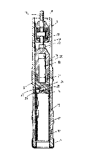
As indica~ed in Fi~u~e 2, the out~ld~ pipe 6 of cor~
: 30 deilling tool 5 con~ist~ o~ s~ve~al pip~ se~tions 14 and
15 which are screwed toge~h~r at l~ a~d are co~nect~d to
core drilling crown 7 by means of a s~r~w conn~tion 1~.

132~3~
In~lde pipe 8 includes a carrying part 1~ whl~h is
uppor~d in pipe ~ and i5 ~orotat~onal with it and a ~ore
pipe part 20 ~ich i ~uspended on the c~rrying part by
~e~ns o~ a bearing lg relative to the ou~side pipe ~ o it
cannot twi~t, In the example shown h~re, core pipe part
20 consi~ts o~ part~ ~3, 24 and ~5, which are ~rewed
to~eth~r at 21 and 2~.
The two parts 23 and 24 o~ ~o~e pipe part 20 together
en~lose the me~urement unit 10 whlch is loc~ted
ac~ofdinyly in the upper area o core pipe part ~0 while
the lower part 25 forms the re~pta~ or a co~e ~ cu~ by
th~ dr~lling ope~at~on. Th~ i~B;de o the low~ part 25
o~ core pipe part ~0 ls ~onne~ted by a p~sage 27 to the
~nnul~r spa~e, but thi~ conhec~lon is ~t~rrup~ed by
lS ball v~lve 2~ in core d~llling oper~tion.
~ B indi~ated in ~igure 3~ which show~ me~sur~m~nt
unit 10 in diagram fo~m, me~surement unit 10 ~y include,
~or example, a measur~d valu~ pickup unit ~ wlt~ ~ number
of me~sured ~alu~ pickup~ 30, ~nly on~ of which i~
illustrated here, ~ processlng unit 31 fo~ data and a
~torage unit 3~ for ~toragQ o~ data. Finally, ~easurem2nt
u~it 10 in~ludes a pow~r ~upply unit 33 to supply it ~i~h
power. In the example illustr~ted here, the power supply
unit co~ista of a set o~ rechar~ea~le eleatric ba~terles.
~5 Inst~ad o~ this, powe~ ~upply unlt 33 may ~l~o con~i~t o~
:~ an ~le~tric ganerator that can ~e driven with d~illing
mud. Nhen recha~geable batteri~ are us~d, a~ i8
pre~erred in mo~t ca~es ~or ~ea~on~ of ~o~t, it i~ ~el~
: evident that th~ batteries shDuld ~pe~ially t~ke into
account the conditions in underground operation,
~specially the tempera~ure condition~.
~h~ me~sur~m~nt unl~ may ha~ an ~ea that i3
: shield~d by a h~a~ prot~ct~on d~vice ~ and i~ provided to
--5--

~327~35
aocommodate heat ~en~it1~Je ~o~nponents ~u~h
micropro~e~sor~, et~ ut in~ead o~ ~his it i; ~l~o
possible to e~auip e~h of 'che respective he~t~en~itive
components with ~ ~eparate heat protection device.
Measured v~lue pickup 30 i~ pre~erred Eo~ acquisition
of data ~uch a~ the borehole ~emperature, ~e bor~hole
~lope, the bor~hole ~imuth, drilllll~ progre~s, ~rilllng
pressur~t torque, rotational spee~, nature o~ the rock,
core ga~n, core advance, csr~ jamming, core orient~tion
10 ~n~/or core propertie~ and th~ da~a pi~ked Up by measure
alue pi~kup~ 30 are proces~ed ac~ording to given pro~r~ms
in proces~in~ unit 31 ~n~ are store in p~o~essed and/or
unp~oce~sed for ln memory unit 3~.
In ~rde~ to send ~he dat~ that h~ve been pi~k~d up,
1$ proce~ed and stored to ~Ln inform~tion ~eceiv~r abc~c e
ground, mea3urement unit 10 c~n b~ removed ~rom th~ upp~r
area o~ core pipe par~ 20 a~ter lnsid~ pipe ~ has ~een
pulled up and the dat~ can be taken from measurement unit
10 by way of it~ communica~ions conne~tion 34 Whi~h can
~0 ~l~o be a~o~iated with re~et~ing mea3ur~m~n~: unit 10 for
a new operatin~ cy~le.
In~e~d of thi~, it i~ also pos~lble to ~rip
me~ urement unit 10 by mean~ of a separate ~ripping tool
(no~ ~hown3 if th* upper end ls arrsng~d so i 'c is exposed
~5 accordin~lyl ~nd the~eby ~'caçh it f~vm th~ cor~ pipe part
2~ below ~round and ~onvey it to the surface ~eparately in
ord~r to pernli~ intermitt~nt data tran~mission
indep~ndently of the proce~s of retracting the in~ide pipe
8.
Inst~ad o~ this, i~ is al~o possi~le 'co h~ve a
~on~tant data trall~mlssion, namely wh~n mea~u~ement uni t
10 i9 linke~l up with a p~es~ure pul~ ~er)erator ~not
shos~n3 to ~niar~te pr~8~Ure pulses in ~he drllling m~ld ~o
--6--

~32~3~
corr~a pond to the processed mea3ured ~t~ sO th~e
pre~sure pul~es can be pic~ed up by means oE ~ensors above
ground .
A ~ontirluous data transmission i~ al~o conceivable by
S way oF ~ line whi~h ~n be looated in the traction
m~chanism 11 when using such a me~h~nlsm that ~n be
connected to inside pip~ ~ by sn~an$ of th~ q~ipping devic0
12. In thi~ c~e, the grippin~ device 1~ and measurement
uni~ lo ~n h~ve con~ecting ~ e~ th~t enter into a dat~
10 transmission mode of engagelnent wh~n inside pipe ~ is
gripped, e.g., ~c~nnectirlg devi~e~ that p~rmit induetive
tran~mi~ion .
In ~pecial oa~es, ~ripping device 12 with it~
tractic:n d~ e ll m~y be in ~orl~tant ~n~agemen~ wi~h
15 in~ide plpe 8 du~ing the core dr~ lling oper~tion~ in order
to as~ure ~ontinuous d~t~ transmi~ion. A~ ~ rule,
howeve~, intermitt~nt data transmission to the abov~-
groun~ information ~eceiver ill the wake of retrac~ ~ on o~
iTsside pipe 8 iq su~f i~ient

Dessin représentatif
Une figure unique qui représente un dessin illustrant l'invention.
États administratifs

2024-08-01 : Dans le cadre de la transition vers les Brevets de nouvelle génération (BNG), la base de données sur les brevets canadiens (BDBC) contient désormais un Historique d'événement plus détaillé, qui reproduit le Journal des événements de notre nouvelle solution interne.

Veuillez noter que les événements débutant par « Inactive : » se réfèrent à des événements qui ne sont plus utilisés dans notre nouvelle solution interne.

Pour une meilleure compréhension de l'état de la demande ou brevet qui figure sur cette page, la rubrique Mise en garde , et les descriptions de Brevet , Historique d'événement , Taxes périodiques et Historique des paiements devraient être consultées.

Historique d'événement

Description Date
Inactive : CIB expirée 2012-01-01
Inactive : CIB de MCD 2006-03-11
Inactive : Demande ad hoc documentée 1997-02-15
Le délai pour l'annulation est expiré 1996-08-17
Lettre envoyée 1996-02-15
Accordé par délivrance 1994-02-15

Historique d'abandonnement

Il n'y a pas d'historique d'abandonnement

Titulaires au dossier

Les titulaires actuels et antérieures au dossier sont affichés en ordre alphabétique.

Titulaires actuels au dossier
BAKER HUGHES INCORPORATED
Titulaires antérieures au dossier
AXEL SPERBER
RAINER JURGENS
Les propriétaires antérieurs qui ne figurent pas dans la liste des « Propriétaires au dossier » apparaîtront dans d'autres documents au dossier.
Documents

Pour visionner les fichiers sélectionnés, entrer le code reCAPTCHA :


Pour visualiser une image, cliquer sur un lien dans la colonne description du document. Pour télécharger l'image (les images), cliquer l'une ou plusieurs cases à cocher dans la première colonne et ensuite cliquer sur le bouton "Télécharger sélection en format PDF (archive Zip)" ou le bouton "Télécharger sélection (en un fichier PDF fusionné)".

Liste des documents de brevet publiés et non publiés sur la BDBC .

Si vous avez des difficultés à accéder au contenu, veuillez communiquer avec le Centre de services à la clientèle au 1-866-997-1936, ou envoyer un courriel au Centre de service à la clientèle de l'OPIC.


Description du
Document 
Date
(aaaa-mm-jj) 
Nombre de pages   Taille de l'image (Ko) 
Page couverture 1994-07-21 1 16
Revendications 1994-07-21 3 113
Dessins 1994-07-21 2 59
Abrégé 1994-07-21 1 24
Description 1994-07-21 6 240
Dessin représentatif 2002-02-25 1 12
Correspondance de la poursuite 1989-10-17 1 16
Demande de l'examinateur 1992-03-02 2 52
Correspondance de la poursuite 1992-06-19 2 41
Demande de l'examinateur 1993-05-19 1 51
Correspondance de la poursuite 1993-08-16 1 16
Correspondance reliée au PCT 1993-11-24 1 20