Note : Les descriptions sont présentées dans la langue officielle dans laquelle elles ont été soumises.
;: ~
~` '
~: ~
;~ 13272~1
-
1 BACKGROUND OF THE INVENTION
Field of the Invention
The present invention relates to an injectlon
molding machine and, more particularly, to an injection
molding machine including a mold for molding disk-shaped
.- I . . . . .
-~ recordlng medlum carrlers such as optlcal dlsk sub-
strates (hereinafter abbreviated to "optical disk
substrates").
.~, .
Discription of the Prior Art
A conventional mold for molding optical disk
, substrates includes an ejector rod for ejecting a molded
;~ substrate, a gate-cutting punch, and an ejector pin for
ejecting a sprue. The substrate-ejecting ejector rod is
.,
movably fitted in the main body of the mold while facing
the cavity. The gate-cutting punch and the sprue~
~, ;~ . :
~Z ejecting ejector pin are movably fitted within the
,.'~. ^, ~ :
;~, ejector rod while concentrically engaging with each
`:
? other in such a manner as to be movable relative to each
other. The conventional mold also incorporates therein
20 a pneumatic cylinder to actuate mechanisms for ejecting
the substrate and a hydraulic cylinder to actuate a
,~ j
gate-cutting mechanism.
:1 However, because the conventional mold
.: -,
~i~ incorporates hydraulic cylinders, various problems
arise. The structure of the mold is complicated.
. ~ .
j - 1 -
, . 'J
,',
13272~
1 During the manufacture of the mold, considerations have
to be given to various mechanisms including the mecha
nism for sealing, e.g., high-pressure hydraulic fluid,
and the mechanism for assuring pressure resistance. In
addition, a great number of component parts are
required. Accordingly, it is an inevitable consequence
that a mold for molding optical disk substrates is
relatively large, heavy, and expensive. Further, proper
maintenance of the mold is difficult~ Still further,
when the sealing of the pressure oil happens to be
inadequate, there is a risk of oil leakage, this being
undesirable particularly in the case of optical disk
substrates which must not be contaminated. Another
problem is that, during the replacement of the mold,
since the component parts that must be connected through
pipe lines include not only a temperature adjusting
device but also the gate-cutting hydraulic cylinder, the
operation of connecting pipe lines is inevitably
laborious.
SUMMARY OF THE INVENTION
The present invention has been made in order
to overcome the above-stated problems. It is an object
of the present invention to provide an injection molding
machine from which those drawbacks resulting from the
incorporation of a hydraulic cylinder in the mold are
eliminated by mounting both a gate-cutting cylinder and
a cylinder for ejecting a substrate and a sprue in a
:. .. .
.. . . .
: . .
25711-554
movable mold-mountlng plate on the slde that is not the ~ide on
which the mold is mounted.
To this endr according to the present lnventlon, there
is provided an injection molding machine, comprising, a mold-
mounting pla~e havlng a fron~ surface for mounting a mold thereon,
a rear sur~ace and a hole extending through said plate and said
front and rear ~urfaces; a ~ubstrate ejecting rod slidably
inser~ed in a front portion of said hole and extending through a
front half and ~aid front surface of ~aid mold-mounting plate,
said substrate ejecting rod having a bore extending longitudinally
in a center thereo~ a gate-cutting punch ~lidably lnserted in
~aid bore of said substrate e~ecting rod and extending through
said mold~mounting plate and æald front and rear surfaces of said
pla~e, said gate-cutting punch havlng a bore extending
longitudlnally in a center thereof a sprue-ejectin~ e~ector pin
slidably inserted in said bore of ~aid gate-cutting punch, ~aid
sprue-ejectin~ ejector pin having a rear end; a gate-cutting drive
aylinder mounted on ~ald rear surfaca of æaid mold-mounting plate
and having a rear surface and a piston for abu~ting against a rear
end of said gate-cutting punch~ said piston haviny a ~tepped bore
- with a large-dlame~er front portlon a~d a small-diameter rear
portion extending axially through said plston; an ejector rod
extending through said ætepped bore of ~aid pi~ton and haviny a
large-diameter portlon ælidable within ~aid large-dia~eter front
portion of ~a~d 6tepped bore and a smali-diameter portion
extending from ~aid large-diameter portion of said ejector rod
forwardly, ~aid ~mall-diameter portion of sa~d ejector rod having
B
.. ~ - . ,
" , ~ , . ~ . .
. .
~3~726~ -
25711-55
a front eDd for abuttlng against said rear end of sald sprue-
ejecting e~ector pin, ~aid ejector rod movable together with aid
piston as said piston moves toward said mold-mounting plate but
otherwise arranged to move lndependently of said piston; a sprue-
ejecting drive cylinder on said rear sur~ace of said gate-cutting
drive cylinder, said sprue-ejectlng drive cylinder having a piston
with a pi~ton rod o~ ~ald piston engagable with a rear end o~ said
ejector rod; and transmittlng means for transmitting forward
movement of said sprue-ejecting ejector pin to said substrate
e~ecting rod to move the ~ame forwardly as said sprue-ejecting
e~ector pin moves forwardly by a predetermined distance.
3a
~` B
,
,
... .
. ~ `. .
13272~
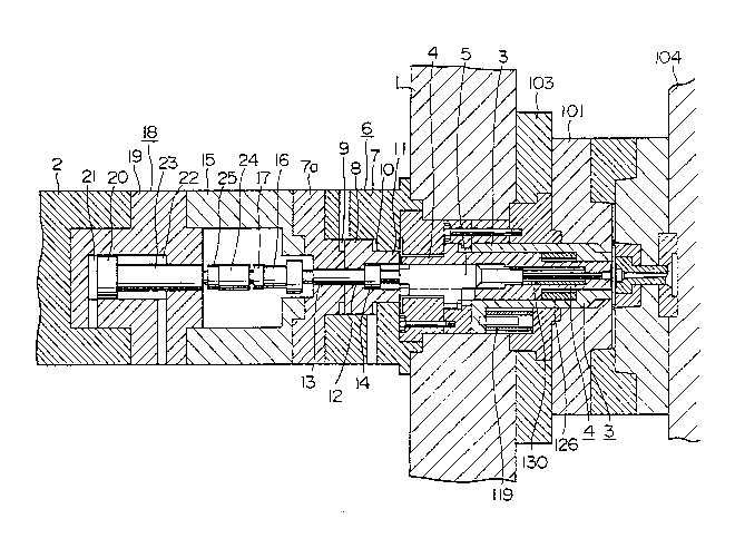
1 BRIEF DESCRIPTION OF THE DRAWING
Fig. 1 is a sectional view of essential parts
of an injection molding machine in accordance with one
embodiment of the present invention, taken through a
plane including the axis of rods of the machine;
Fig. 2 is a perspective view of a part of a
gate-cutting punch; and
Fig. 3 is a perspective view of a sprue-
ejecting ejector pin.
DESCRIPTION OF THE PREFERRED EMBODIMENT
The preferred embodiment of the present
invention will now be described with reference to the
drawing.
In the drawing, reference numeral 1 denotes a
movable mold-mounting plate dlsposed in opposition to a
fixed mold-mounting plate 104 in such a manner as to be
movable toward and away from the fixed mold-mounting
plate when moved by a mold-clamping device (i.e., a
mold-clamping cylinder, in this embodiment).
A movable part of the mold is mounted on the
movable mold-mounting plate 1.
In the movable part of the mold, an ejector
rod 3 for ejecting a molded substrate is movably fitted
in the main body 103,101 of the mold while facing the
cavity. A gate-cutting punch 4 and a sprue~ejecting
ejector pin 5 are movably fitted through a longitudinal
bore formed in the center of the substrate-ejecting
. .
~., . . :
, I'; . ! ~' ' ' '
~L327~6~
1 ejector rod 3 while concentrically engaging with each
other in such a manner as to be movable relative to each
other. Return springs 119, 126 and 130 urge the sub-
strate-ejecting ejector rod 3, the gate-cutting punch 4,
and the sprue-ejecting ejector pin 5 with forces capable
of returning these members to their most retracted
positions. The arrangement of the substrate-ejecting
ejector rod 3 is such that, after the sprue-ejecting
ejector pin 5 has advanced toward the cavity by a
certain distance (a distance greater than the gate-
cutting distance), a projection 128 (See Fig. 3) of the
ejector pin 5 comes into contact with the substrate-
ejecting ejector rod 3 so that the substrate ejecting
ejector rod 3 advances in synchronization with the
advancement of the ejector pin 5.
Fig. 1 shows the state where the movable part
103,101 of the mold is mounted on the movable mold-
mounting plate 1, and, simultaneously, the substrate-
ejecting ejector rod 3, the gate-cutting punch 4, and
the sprue-ejecting ejector pin 5 are inserted in a hole
extending through the movable mold-mounting plate 1
while all of these members 3 to 5 are retracted to the
side remote from the side on which the~ mold is mounted.
A gate cutting drive cylinder 6 is mounted on
the rear side of the movable mold-mounting plate 1 which
is not the side on which the mold is mounted.
The drive cylinder 6 has a piston 8 movably
received in a cylinder block 7, with oil chambers 9 and
.
. .
'
.
.
~3272Sl
1 10 defined behind and ahead of the plston 8, respective-
ly .
The piston 8 has, on its side close to the
movable mold-mounting plate 1, a ring-shaped abutting
portion 11 capable of abutting against the gate-cutting
punch 4 inserted through the movable mold-mounting plate
1 and associated wlth the mold. A bore 12 is formed in
the center of the piston 8 in such a manner as to face
the inside of the ring-shaped abutting portion 11, and
has a diameter smaller than the bore defined inside the
portion 11.
An ejector rod 13 is movably inserted in the
piston 8. The ejector rod 13 is, at its front end,
capable of abutting against the sprue-ejecting ~jector
pin 5 inserted through the movab1e mold-mounting plate 1
and associated with the mold. The ejector rod 13 has,
at its intermediate position, a large-diameter portion
14. The side of this large-diameter portion 14 which is
remote from the sprue-ejecting ejector pin 5 is
engageable with the piston 8 so as to allow engagement
between the ejector rod 13 and the piston 8.
The ejector rod 13 extends rearwardly through
the cylinder block 7 and into a spacer block 15. A
stroke-adjusting stopper 16 allowing the stroke of the
longitudinal movement of the eiector rod 13 to be
adjusted is fixed to a rear end portion of the rod 13 by
means of a lock nut 17.
A sprue-ejecting drive cyli.nder 18 is provided
- -
,., . .
. .. .
~7~6~
1 concentrically with the gate cutting drive cylinder 6 on
that side of the drive-cylinder 6 which is remote ~rom
the mold, with the spacer block 15 disposed between the
drive cylinders 6 and 18.
The drive cylinder 13 has a piston 20 movably
received in a cylinder block 19, with oil chambers 21
and 22 defined behind and ahead of the piston 20. A
piston rod 23 of the piston 20 extends frontwardly
through the cylinder block 19 and into the spacer block
15.
The piston rod 23 is connected to the e~ector
rod 13 by means of a link nut 24, and this connection is
locked by a lock nut 25.
The spacer block 15 has a hollowed out
structure in which the block 15 is open on one side
thereof, so that the ejector rod 13 and the piston rod
23 can be connected to each other, and the position of
the stroke-adjusting stopper 16 can be adjusted,
utilizing the opening.
The above-described sprue-ejecting drive
; cylinder 18 and the gate~cutting drive cylinder 6 are
respectively controlled by independent control circuits
(not shown).
The clamping device (the ram o~ the clamping
cylinder alone is shown in the drawing) is connected to
the movable mold-mounting plate 1 via the above-
described gate-cutting drive cylinder 6, the spacer
block 15, and the sprue-ejecting drive cylinder 18.
.
- :
13272~
1 The operation of the machine will be
described.
After the injection molding of a substrate, an
ejecting operation is performed first by the gate-
cutting cylinder 6. Specifically, when pressure oil issupplied to the rear oil chamber 9 while the front oil
chamber 10 communicates with an associated tank (not
shown), the piston 8 advances toward the movable
mold-mounting plate 1. This advancement causes the
ring-shaped abutting portion 11 of the piston 8 to abut
against the gate-cutting punch 4 and to push the punch 4
against the force of the return spring 126. As a
result, the gate-cutting punch 4 advances within the
substrate-ejecting ejector rod 3 until it projects by a
distance approximately corresponding to the thickness of
a substrate, thereby performiny a gate-cutting action.
At this time, the ejector rod 13 has its
surface on the side remote from the sprue-ejecting
ejector pin 5 kept in contact with the piston 8.
Therefore, during the gate-cutting action, the ejector
rod 13 moves together with the piston 3 toward the
movable mold-mounting plate 1. In this way, the mutual
relationship ln position between the ejector rod 13 and
the piston 8 is maintained.
Thereafter, the movable mold-mounting plate 1
: is retracted to open the mold. After this mold-opening
operation, an ejecting operation is performed by the
sprue-ejecting drive cylinder 18. Specifically, when
. . .
: . .
132726~
1 pressure oil is supplled to the rear oll chamber 21
while the front oil chamber 22 communicates with an
assoclated tank, the plston 20 and the plston rod 23
advance toward the movable mold-mounting plate 1. The
plston rod 23 ls connected to the ejector rod 13 via the
llnk nut 24 and the iock nut 25. Therefore, the ejector
rod 13 also advances a certain distance from its
position resulting from lts movement together with the
plston 8 untll the stroke-adjustlng stopper 16 abuts
agalnst the cylinder block 7a. As the ejector rod 13
advances, it pushes the sprue-ejecting ejector pin 5
against the force of the return spring 130. As a
result, a sprue-ejecting action is performed.
The projections 128 provided on the rear end
portion of the sprue-ejecting ejector pin S are project-
ed outwardly through grooves 121 of the gate-cutting
punch 4 (See Fig. 2) and axially move along the grooves
4 so as to be capable of abutting against the rear end
of the substrate-ejecting ejector rod 3. For this
arrangement, when the sprue-ejecting ejector pin 5 has
advanced a certain distance (a distance greater than the
gate-cutting distance), the projections 128 abut against
the rear end of the substrate-ejecting ejector rod 3 so
that the substrate-ejecting rod 3 advances in synchroni-
zation with the sprue-ejecting ejector pin 5. As the
substrate-ejecting ejector rod 3 advances, it is brought
into abutment with the inner peripheral portion of the
substrate and pushes the substrate against the force of
_ 9 _
: '
~3272~
1 the return spring 126, thereby performing a substrate-
ejecting action substantially in synchronization with
the sprue-ejecting action.
After the completion of the sprue-ejecting
action and the substrate-ejecting action, operations
that are contrary to those described above take place.
Changeover valves in the control circuits for the
sprue-ejecting drive cylinder 18 and the gate-cutting
drive cylinder 6 are operated in such a manner that
pressure oil is supplied to the front oil chamber 22
whi]e the rear oil chamber 21 communicates with the
tank, thereby retracting the spruce-ejecting drive
cylinder 18. Thereafter, pressure oil is supplied to
the front oil chamber 10 while the rear oil chamber 9
communicates with the tank, thereby retracting the
gate-cutting drive cylinder 6. When these drive
cylinders 1~ and 6 are retracted in this way, the
substrate-ejecting ejector rod 3, the gate-cutting punch
4,~and the sprue-ejecting ejector pin 5, which are urged
by the springs 119, 126 and 130 with a force capable of
returning these members to their most retracted
positions, automatically return to their respective
initial positions.
The operation of replacing the mold is
performed by dismounting the movable mold part mounted
on the movable mold-mounting plate 1 and then mounting a
new movable mold part. At this time, the gate-cutting
drive cylinder 6 and the sprue-ejecting drive cylinder
-- 10 --
-
1~27~
1 1~ do not require the operation of connecting them
through pipe lines.
In the foregoing embodiment, the injection
molding machine is described as used to mold disk
substrates. However, this is a mere example r and it
would be easily understood that the present invention is
also applicable to molding machines exclusively for use
in the molding of various othe- molded products so far
as the molding of the product involves a single action.
As described above, according to the present
invention, both the gate-cutting drive cylinder and the
sprue-ejecting drive cylinder are mounted on the mold-
mounting plate and are not provided on the same side as
the mold. This arrangement i5 advantageous in Lhat t'ne
work of the injection molding machine can be clearly
divided between two parts of the machine, the part
including the mold taking over the achievement of
precise dimensions, another part of the machine taking
over the drive mechanisms. This allotment of work
enables the mold to be manufactured without need for
considerations to be given to such mechanisms as the
mechanism for sealing, e.g., high-pressure hydraulic
fluid, and the mechanism for assuring pressure
resistance. Accordingly, the mold can be designed and
manufactured with ease, while also facilitating the
addition of mechanisms for adjusting tha gate-cutting
distance and the ejecting distance.
Furthermore, the structure of the mold is
-- 11 --
-- ~
: . :;.; .~ .~ ' :
. : - .
:,
.;
. .
~2~261
1 rendered simple because such mechanism as the high-
pressure hydraulic fluid sealing mechanism, and the
pressure-resistance assuring mechanism are eliminated,
and the number of the required component parts is
reduced. Accordingly, the size and the weight of the
mold can be reduced by a great extent.
Still further, the replacement of pressure-oil
packings will not be necessary, the mold will not ha~e
to be disassembled so frequently as before, and the
operation of establishing connection through pipe lines
during the replacement of the mold will be simplified.
In this way, the maintenance of the mold is facilitated
by a great extent.
..
:
: , ,~. .. . . .