Sélection de la langue

Search

Sommaire du brevet 1327378 

Énoncé de désistement de responsabilité concernant l'information provenant de tiers

Une partie des informations de ce site Web a été fournie par des sources externes. Le gouvernement du Canada n'assume aucune responsabilité concernant la précision, l'actualité ou la fiabilité des informations fournies par les sources externes. Les utilisateurs qui désirent employer cette information devraient consulter directement la source des informations. Le contenu fourni par les sources externes n'est pas assujetti aux exigences sur les langues officielles, la protection des renseignements personnels et l'accessibilité.

Disponibilité de l'Abrégé et des Revendications

L'apparition de différences dans le texte et l'image des Revendications et de l'Abrégé dépend du moment auquel le document est publié. Les textes des Revendications et de l'Abrégé sont affichés :

  • lorsque la demande peut être examinée par le public;
  • lorsque le brevet est émis (délivrance).
(12) Brevet: (11) CA 1327378
(21) Numéro de la demande: 1327378
(54) Titre français: OSSATURE DE VALISE
(54) Titre anglais: SUITECASE FRAME
Statut: Périmé et au-delà du délai pour l’annulation
Données bibliographiques
(51) Classification internationale des brevets (CIB):
  • A45C 05/14 (2006.01)
(72) Inventeurs :
  • VERHEIJ, JOHANNES WILLEM
  • VAN PEER, IRENE PETRA
(73) Titulaires :
  • HOMAR N.V.
(71) Demandeurs :
  • HOMAR N.V. (Antilles Néerlandaises)
(74) Agent: SMART & BIGGAR LP
(74) Co-agent:
(45) Délivré: 1994-03-01
(22) Date de dépôt: 1989-06-23
Licence disponible: S.O.
Cédé au domaine public: S.O.
(25) Langue des documents déposés: Anglais

Traité de coopération en matière de brevets (PCT): Non

(30) Données de priorité de la demande:
Numéro de la demande Pays / territoire Date
8801617 (Pays-Bas (Royaume des)) 1988-06-24

Abrégés

Abrégé anglais


ABSTRACT
Suitcase frame
A suitcase frame (1) provided with means to carry
luggage and a document suitcase as well. The frame is
provided with carrying wheels (6, 7) pivotable between a
position inside the frame (1) and an operable position
outside the frame (1). The wheels (6, 7) are actuated by the
handle (10) of the suitcase frame (1).

Revendications

Note : Les revendications sont présentées dans la langue officielle dans laquelle elles ont été soumises.


THE EMBODIMENTS OF THE INVENTION IN WHICH AN EXCLUSIVE
PROPERTY OR PRIVILEGE IS CLAIMED ARE DEFINED AS FOLLOWS:
1. A suitcase frame, comprising a first double wall having
a carrying space, a bottom part connected to said double wall, a
carrying wheel pivotally attached to said first double wall so
that said carrying wheel can pivot between a rest position in the
carrying space of said first double wall and an active position
outside that space, means for actuating and causing said wheel to
pivot, said means including a pivot arm connected to said wheel
and pivotally connected to said double wall, said pivot arm having
a channel-shaped guiding track, a roller received by and movable
within said guiding track and a bracket connected to said roller,
and means for fixing said bracket in a fully extended position
when said first wheel is in the active position, comprising a
first guide track including a telescopically slidable guide
mounted to said bracket, a flexible element having one end mounted
near said bottom part and slidably received by said first guide
track, and a blocking element mounted to said bracket, said
blocking element having a flexible element receiving bore movable
between a first position which permits another end of said
flexible element to pass through said bore and a second position
which prevents said other end of said flexible element from
passing through said bore, said flexible element having a length
such that when the bracket is in the fully extended position said
flexible element other end cannot enter said bore.
2. The suitcase frame of claim 1 further comprising a

8
second double wall having a carrying space connected to said
bottom part and arranged parallel to and at a distance from said
first double wall, a second carrying wheel pivotally attached to
said second double wall so that said second carrying wheel can
pivot between a rest position in the second double wall carrying
space and an active position outside the second double wall
carrying space and means for actuating and causing said second
wheel to pivot.
3. The suitcase frame of claim 1 wherein said bracket is
slidable to an extended position and a retracted position in a
lengthwise direction within said first double wall, so that when
said bracket is extended in the extended position said first
carrying wheel is in the active position outside said first
carrying space and when the bracket is retracted to the retracted
position said first carrying wheel is in the rest position inside
said first carrying space.
4. The suitcase frame of claim 3 wherein said bracket
includes a telescopic leg attached to said roller.
5. The suitcase of claim 1 further comprising means for
positioning said pivot arm in the active position and in the rest
position.
6. The suitcase of claim 5 wherein said means for
positioning said pivot arm in the active position and in the rest
position include a stop member pivotally mounted to said first

double wall and a spring mounted to said stop member, and a stop
member receiving recess in said pivot arm whereby when said
carrying wheel is in the rest position said stop member is
disengaged from said stop member receiving recess of said pivot
arm and when said carrying wheel is in the active position said
spring acts upon said stop member to bias the stop member into
engagement with said stop member receiving recess of said pivot
arm and thereby locking the wheels in an active position.
7. The suitcase of claim 5 wherein said means for
positioning said pivot arm in the active position and in the rest
position include a first nose member and a second nose member
mounted to said first double wall and said pivot arm includes a
first nose receiving recess and a second nose receiving recess
whereby when said first wheel is in the rest position said first
nose is received by said first nose receiving recess and when said
first wheel is in the active position said second nose is received
by said second nose receiving recess.
8. The suitcase frame of claim 1 wherein said means for
fixing said bracket in a fully extended position when said first
wheel is in the active position further includes a second guide
track having a telescopically slidable guide mounted to said
bracket and positioned parallel to said first guide track, and a
second flexible element having one end mounted near said bottom
part so that said mounted ends of said first and second flexible
elements are positioned away from each other on opposite sides of
said bottom part.

9. The suitcase frame of claim 1, wherein said means for
fixing said bracket in a fully extended position when said first
wheel is in the active position further includes a blocking spring
mounted in said bracket which contacts said blocking element
whereby when said blocking spring is in a relaxed state said
blocking element is in the first position, blocking the passage
for said flexible element other end through said flexible element
receiving bore, and when said blocking spring being in a loaded
state said blocking element in a second position, clearing the
passage for said other end of said flexible element to pass
through said flexible element receiving bore.
10. The suitcase frame of claim 1, wherein one end of said
telescopic guide is threadably mounted to said first double wall.
11. The suitcase frame of claim 1 further including latches
mounted to said bracket.
12. The suitcase frame of claim 1 further including a second
spring mounted to said first double wall whereby said second
spring is maintained in a loaded state against said bracket when
said bracket is in a retracted state and said second spring is
maintained in a relaxed state when said bracket is in an extended
state.
13. The suitcase frame as claimed in claim 2 wherein a first
suitcase is defined by said first double wall and said second
double wall and the spacing therebetween.

11
14. The suitcase frame as claimed in claim 13 wherein said
first double wall and said second double wall form two side walls
of said first suitcase.
15. The suitcase frame as claimed in claim 13 wherein a
second suitcase is releasably attached to said first and second
double walls.
16. The suitcase frame as claimed in claim 14 wherein said
first suitcase has a displaceable bottom connected to said side
walls by means of a bellows construction.
17. The suitcase frame as claimed in claim 14 wherein said
first suitcase has a rounded upper wall connected to said side
walls.
18. The suitcase frame of claim 13 wherein said bottom part
forms a bottom wall of said first suitcase.
19. The suitcase frame of claim 13 wherein said first
suitcase further includes a handle attached thereto and received
by a handle receiving slot.
20. The suitcase frame of claim 1 further including
extendable carrying arms attached to said bottom part.
21. The suitcase frame of claim 2 wherein said bracket is U-
shaped.

12
22. A suitcase frame, comprising a first double wall having
a carrying space, a bottom part connected to said double wall, a
carrying wheel pivotally attached to said first double wall so
that said carrying wheel can pivot between a rest position in the
carrying space of said first double wall and an active position
outside that space, means for actuating and causing said wheel to
pivot, said means including a pivot arm connected to said wheel
and pivotally connected to said double wall, said pivot arm having
a channel-shaped guiding track, a roller received by and movable
within said guiding track and a bracket connected to said roller,
and means for positioning said pivot arm in the active position
and in the rest position including a stop member pivotally mounted
to said first double wall and a spring mounted to said stop
member, and a stop member receiving recess in said pivot arm
whereby when said carrying wheel is in the rest position said stop
member is disengaged from said stop member receiving recess of
said pivot arm and when said carrying wheel is in the active
position said spring acts upon said stop member to bias the stop
member into engagement with said stop member receiving recess of
said pivot arm and thereby locking the wheels in an active
position.

Description

Note : Les descriptions sont présentées dans la langue officielle dans laquelle elles ont été soumises.


1 32737~
.
1 21766-553
The invention relates to a suitcase frame. The
transportation and handling of suitcases forms a continual problem
for different reasons. If a large suitcase is chosen then one
r~ encounters ~he drawback that it becomes heavy and awkward to
handle. An attempt has been made to solve this problem by
providing larger suitcases with carrying wheels. However, small-
- size carrying wheels are chosen in order not to make the use of
the suitcase awkward for the user. Because of this the suitcase
rolls with difficulty when it is pulled along. Use is further
made of portable folding framework-type frames onto which the
suitcase is laid in order to enable it to be pulled along. The
carrying of such a frame is awkward however. Moreover, certain
reguirements are made of suitcases in respect of the dimensions,
.:
particularly when these are used as so-called hand luggage in air
traffic. If a suitcase i~ to be taken into the airplane then it
must be stowable in the luggage space above the seating areas or
under the seat or it has to be possible to place it against the
- edge of the seat covered by the legs of the seated passenger.
Smaller suitcases do of course comply with this requirement but
these have the drawback of limited carrying volume.
~` The invention has for its object to provide a suitcase
.~
which, in view of the dimensions thereof, can be used a~ so-called
, hand luggage, has a reasonable, preferably divisible capacity, on
.~.
the one side for instance for clothing, and on the other slde for
documents, and which can moreover be transported without all too
great a physical effort.
The invention provldes a sultcase frame, comprisiny a
first double wall having a carrying space, a bottom part connected
~' ~
r,,', C

1 327378
2 ^ 217fi6-553
to said double wall, a carrying wheel pivo~ally attached to said
: first double wall so that said carrying wheel can pivot between a
rest position in the carrying space of said first double wall and
an active position outside that space, means for actua~ing and
: causing said wheel to pivot, said means including a pivot arm
connected to said wheel and pivotally connected to said double
wall, said pivot arm having a channel-shaped guiding track, a
roller received by and movable within said guiding track and a
bracket connected to said roller, and means for fixing said
hracket in a fully extended position when said first wheel is in
the active position/ comprising a first guide track including a
telescopically slidable guide mounted to said bracket, a flexible
5~; element having one end mounted near said bottom part and slidably
received by said first guide track, and a blocking element mounted
i:. to said bracket, said blocking element having a flexible element
receiving bore movable between a first position which permits
~ another end of said flexible element to pass through said bore and
: a second position which prevents said other end of said flexihle
element from passln~ through said bore, said flexible element
having a length such that when the bracket is in the fully
extended position sa~d flexible element other end cannot enter
'`: said bore.
The invention also provldes a suitcase frame, comprising
a first double wall having a carrying space, a bottom part
. connected to said double wall, a carrying wheel pivotally attached
to said first double wall so that said carrying wheel can pivot
between a rest position in She carrying space of said first double
wall and an active position outside that space, means for
.~
~,

~ 3~7378
2a 21766-553
actua~ing and causing said wheel to pivot, said means including a
pivot arm connected to said wheel and pivotally connected to said
double wall, said pivot arm having a channel-shaped guiding track,
~: a roller received by and movable within said guiding track and a
bracket connected to said roller, and means for positioning said
pivot ar~ in the ac~ive position and ln the rest position
including a stop ~ember pivotally mounted to said first double
-: wall and a spring mounted to said stop member, and a stop member
receiving recess in said pivot arm whereby when said carrying
wheel is in the rest position said stop member is disengaged from
said stop member receiving recess of ~aid pivot arm and when said
carrying wheel is in the active position said spring acts upon
` said stop member to bias the stop member into engagement with said
i stop member receiving recess of said pivot arm and thereby locking
the wheels in an active position.
With such a suitcase frame there is the possibility of
causing the carrying wheels to plvot outwards for transportatlon
and of making the suitcase roll forwards, and, for the non-
transporting posltion, of causing the wheels to pivot into the
~,
` 20 space between the double walls so that the suitcase can be handled
~ like any other suitcase.
The bracket is preferably slidable in the lengthwise
~;. direction of the walls, such that when the bracket is extended the
.~,
`~` carrying wheels are in the posltlon outside the space in the
y.: double walls and when the bracket is retracted the carrying wheels
.,~
are inside this space.
The bracket, which is for example U-shaped and whereby
each leg of the U is inserted into a double wall, is used as both
.,
.:
.

2b 1 327378 21766-553
- actuator for the actuating system for the carrying wheels and in
extended position as pulling bracket for transporting the
suitcase. In order to achieve a sufficient length for the pulling
bracket the legs preferably consist of telescopically extendable
parts. For enabling the bracket to withstand compressing loads
encountered during use, the bracket is preferably provided with
means for fixing it in its fully extended position.
~ As well as performing a pivoting movement while
,- swivelling into the acttve position the rotating shafts of the
,~. 10 carrying wheels also perform a translation movement.
Owing to the coupling of the extension movement of the
pulling bracket and the pivoting of the carrying wheels to or from
the active position both the pivoting movement of the carrying
~; wheels and the extension movement of the legs of the U-shaped
bracket are synchronized. This is lmportant since if extension of
~: the leg~ of the U is non-synchronized there is the danger that
j they will go out of ~quare and jar.
:
.
,
'. ~

; 1 327378
Arranged between the walls of the frame is a first
suitcase. A second suitcase can be detachably arranged against
the bottom wall of the first suitcase. The first suitcase can
- thereby be a clothing suitcase for example, whlle the second
;~ 05 suitcase can be a so-called attache case. The first suitcase
can have a moveable bottom connected to the side walls over a
bellows construction. In the absence of the second attache
s case the bottom wall of the first sultcase can be brought
,- outwards so that the loading space is enlarged. The first
suitcase preferably has a rounded upper wall such that when
!. the suitcase frame with suitcase is disposed on the floor
against the seat for example of an alrplane seat the user i8
not thereby obstructed since the suitcaæe ~atches the shape
of the seat.
Other features and advantages of the inventlon will
become apparent from the descriptlon of embodl~ents as accor-
ding to the annexed drawings. In the drawings:
~; fig. 1 shows in perspective vlew and in dismantled
state the suitcase frame with two suitcases arranged therein,
fig. 2 shows the suitcase frame according to the
inventlon with extended bracket and carrylng wheels moved
outwards,
flg. 3 shows ln perspective view the sultcase frame
in the transportlng po~ltion,
flg. 4 shows ln perspectlve view an e~bodi~ent of
`~ the actuatln8 syste~ for the carrying wheels,
fig. S shows partlal sectio~-l per~pectivo vlow
o~ tha nuitcas~ fra~e in the transporting position,
fig. 6 shows a ~ectional parspectlvo view along the
line VI in fig. 5,
,. j ~
A
.

1 32737~
fig. 7 shows a perspeetive view along the line VII
; in fig. l.
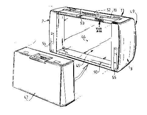
The suitcase frame l consists substantially of t~o
double walls 2 and 3 arranged parallel to and at a distance
, 05 from each other, a bottom part 50 dividing the walls, and the
U-shaped pulling bracket lO, which iS coupled to an actuating
system for the carrying wheels 6, 7 such that when the bracket
10 is extended (fig. 2 and 3) the carrying wheels are ln the
active position and when it is in the retracted position
i 10 (fig. l) the wheels are in the rest position. In the suitcase
frame are a pair of cases, a comparatively larger case 45 and
a comparatively smaller case, a so-called attache case, 47.
The attache case 47 is removable (fig. l) and can be used as
a case independently. The bottom wall 46 of the first case is
~ 15 pr~ferably movable using the bellows construction 48 so that
.~ it can be moved as according to the arrow in fig. l in order
to be able to enlarge the packing space when the attache ca~e
47 is absent. The whole can be carried using the carrylng
grip 52, which is movable in the slot 53. Depending on the
presence of the attache case 47 the carrying grip 52 can be
~ placed in the slot 53 in the most favourable position relative
,~- to the centre of gravity.
In the rest position the carrying wheels 6, 7 are
held in the space 4, 5 in the respective double walls 2, 3.
In the rest position the access space for the wheels i9 closed
off by the respective flaps 54 and 55. The flap is biased to
t`: the closed position- The sultcase displays on one side a
~ rounded form 49 such that when the sultcase is placed against
'~ a seat in an airplane the user 8itting on the seat i8 not
~` 30 obstructed.
Arms 56, 57 are retractable into and extendable
out of the bottom part 50, which arm8 can aerve ln the ex-
tended positlon (fig. 3) to accommodate a third ~ultca~e or
bag lying separately on the sultcase frame.
The legs 11, 12 of the U-shaped bracket 10 con~i~t
of three telescopically extendsble part~ 28, 29, 30.
'''';
.
,;
~: A

5 1 32737`~
, The actuating system 8 comprlses a pivot arm 19
, which is connected to the relevant carrying wheel 6. The
-~ ,pivot arm is pivotable around the pivot shaft 18 which is
slidable in the slot 15. Present in the pivot arm 19 is a
channel-shaped guiding track 17 in which can move a roller 20
., connected to the bracket 10. When the bracket is pulled out
`~ the roller 20 moves in the channel-shaped guiding track 17
'' and ~orces this into pivoting to the outside and into a erans-
'~' latLon through the slot 15, whereby the movement initially ~s
- 10 a mainly pivoting movement and in the latter portion of the
path a translation movement through the slot 15. In the opera-
' tive position of the carrying wheel, that is, th~ position
~- outside the space between the double walls, the pi~ot arm
,' is fixed in form fitting manner by co-action of the nose 21
~, 15 and the recess 22 in the pivot arm. A similar fixatlon
~,occurs in the rest position using the nose 23 and the recess
24. The wheels are arrested in their active pos,ition using a
;j,stop member 25 which is under the influence of the leaf spring
c26 and which can pivot around the pivot ~haft 58. During the
move~ent to the active position the stop ~ember 25 falls wlth
the nose 59 behind the angle-shaped recess 27. When the brac-
~;~ket 10 is pushed inward the stop ~ember 25 is pu~hed aside 80
~that disengage~ent takes place.
'~As can be seen for example from fig. 4, in the rest
~',25 position the body 44 of the U-shaped bracket is recessed lnto
,the groo~e 60. The brack~t 10 i8 fixsd in this position b~
c,two commercially available latches 13, 14. Springs 62, 63
between the second telescopic psrt 29 of each log 11, 12 of
,;said bracket 10 and the botto~ part 50 o~ said framo 1 QnsUre
~ 30 that said bracket 10 pOp8 Up upon r~lease of said latches 13,
< 14.
For fixing th~ U-3hapad brac~et 10 in its fully
extended position, fixat1On means 9 i8 provided. Figur3s 5
~' and ~ show one ambodlment of the fixation mean~ 9. In thi~
" 35 embodiment the bottom part S0 o$ tho suitcase frame 1 is
~provided ~ith a doubler alement 31 in 11ne ~ith each leg 11,
'~ ~ 12 of the bracket 10t each ssid doublcr alement 31 bsing
~ A

~ 6 1 32737~
,
provided with a threaded opening 32 accommodating an
;~ adjustment screw 33. To the adju~tment screw 33 is attached
one end of the thinnest member 34 of a commercially available
:~ telescopic antenna 36, mounted inside the U-shaped brackat
05 10. To the other end of said thinne~t antenna member 34 a
flexible element 37 is attached, which runs along the inside
of said telescoplc antenna 36 in a snug fit, and which
continues in a snug fit along the inside of tubular member~
38, 39 that are connected to antenna 36 and that run the
.. 10 length of the body 44 of said U-shaped bracket 10. The length
of the fl~xible element 37 i8 ~uch, th~t when the bracket 10
.~ is retracted, ~aid flexible elem~nt 37 pa~ses through a
,~ blocking element 40, but that when said bracket 10 is fully
: extended, ~aid flexible element 37 stops ~ust short of ~aid
15 blocking element 40. The blocking element 40 comprises a body
65, provided with at least one hole 66 running the length o~
. said body 65, said body 65 bein8 mo~ably mounted in the body
44 of the U-shapQd bracket 10 in such a way, that ~hen said
body 65 i~ in a first po~itlon, extend~ng partly th~ough an
20 opening 67 in the lower skin of ~aid body 44 of said brack~t
10, ~aid body 65 acts to block the pa~sage between the
tubular mambers 38, 39, thereby prohibiting movem0nt of ~ait
flexible ~lement 37, whereas when said body 65 i8 in a ~acond
po~ition, complately ~unk into the body 44 o~ brac~et 10, the
25 hole 66 in said body 65 acts a~ a pasa~geway bet~ee~ the
tubular member~ 38, 39, thus allo~in~ mov~ment of said
flexible ele~ent 37 through said tubular member~ 38, 39. The
.~ body 65 of blocking olement 40 i8 spring mounted and biased
to a psssag2 blocking poaition.
30 The suitcase 45 i8 provided ~lth an extra security measure
in the form of a chaln or cable 68 closable around for example
a post or plllar or the like. In the rest position the cable
68 is wound a~ound a biased spool 69 (fig. 7 ). By operating
,: the combination lock 70 the panel 71 can be moved out~ards,
35 the cable 68 can be pulled from the spool and the loo~e end
~ placed in a locking openlng 72. Subsequently the panel 71 i8
'. closed again.
.
. *****
.
~ A
, .
,

Dessin représentatif
Une figure unique qui représente un dessin illustrant l'invention.
États administratifs

2024-08-01 : Dans le cadre de la transition vers les Brevets de nouvelle génération (BNG), la base de données sur les brevets canadiens (BDBC) contient désormais un Historique d'événement plus détaillé, qui reproduit le Journal des événements de notre nouvelle solution interne.

Veuillez noter que les événements débutant par « Inactive : » se réfèrent à des événements qui ne sont plus utilisés dans notre nouvelle solution interne.

Pour une meilleure compréhension de l'état de la demande ou brevet qui figure sur cette page, la rubrique Mise en garde , et les descriptions de Brevet , Historique d'événement , Taxes périodiques et Historique des paiements devraient être consultées.

Historique d'événement

Description Date
Le délai pour l'annulation est expiré 2004-03-01
Lettre envoyée 2003-03-03
Inactive : TME en retard traitée 2002-03-19
Inactive : TME en retard traitée 2001-05-31
Lettre envoyée 2001-03-01
Inactive : TME en retard traitée 2000-05-31
Lettre envoyée 2000-03-01
Inactive : TME en retard traitée 1999-06-15
Lettre envoyée 1999-03-01
Inactive : TME en retard traitée 1998-03-05
Lettre envoyée 1998-03-02
Inactive : Demande ad hoc documentée 1998-03-01
Lettre envoyée 1997-03-03
Accordé par délivrance 1994-03-01

Historique d'abandonnement

Il n'y a pas d'historique d'abandonnement

Historique des taxes

Type de taxes Anniversaire Échéance Date payée
TM (catégorie 1, 4e anniv.) - générale 1998-03-02 1998-03-05
Annulation de la péremption réputée 2002-03-01 1998-03-05
Annulation de la péremption réputée 2002-03-01 1999-06-15
TM (catégorie 1, 5e anniv.) - générale 1999-03-01 1999-06-15
Annulation de la péremption réputée 2002-03-01 2000-05-31
TM (catégorie 1, 6e anniv.) - générale 2000-03-01 2000-05-31
Annulation de la péremption réputée 2002-03-01 2001-05-31
TM (catégorie 1, 7e anniv.) - générale 2001-03-01 2001-05-31
Annulation de la péremption réputée 2002-03-01 2002-03-19
TM (catégorie 1, 8e anniv.) - générale 2002-03-01 2002-03-19
Titulaires au dossier

Les titulaires actuels et antérieures au dossier sont affichés en ordre alphabétique.

Titulaires actuels au dossier
HOMAR N.V.
Titulaires antérieures au dossier
IRENE PETRA VAN PEER
JOHANNES WILLEM VERHEIJ
Les propriétaires antérieurs qui ne figurent pas dans la liste des « Propriétaires au dossier » apparaîtront dans d'autres documents au dossier.
Documents

Pour visionner les fichiers sélectionnés, entrer le code reCAPTCHA :


Pour visualiser une image, cliquer sur un lien dans la colonne description du document. Pour télécharger l'image (les images), cliquer l'une ou plusieurs cases à cocher dans la première colonne et ensuite cliquer sur le bouton "Télécharger sélection en format PDF (archive Zip)" ou le bouton "Télécharger sélection (en un fichier PDF fusionné)".

Liste des documents de brevet publiés et non publiés sur la BDBC .

Si vous avez des difficultés à accéder au contenu, veuillez communiquer avec le Centre de services à la clientèle au 1-866-997-1936, ou envoyer un courriel au Centre de service à la clientèle de l'OPIC.


Description du
Document 
Date
(aaaa-mm-jj) 
Nombre de pages   Taille de l'image (Ko) 
Revendications 1994-07-20 6 198
Abrégé 1994-07-20 1 10
Dessins 1994-07-20 5 175
Description 1994-07-20 8 299
Dessin représentatif 2000-08-20 1 23
Avis concernant la taxe de maintien 1998-03-29 1 179
Quittance d'un paiement en retard 1998-04-05 1 172
Avis concernant la taxe de maintien 1999-03-28 1 179
Quittance d'un paiement en retard 1999-06-17 1 172
Avis concernant la taxe de maintien 2000-03-28 1 178
Quittance d'un paiement en retard 2000-06-07 1 171
Avis concernant la taxe de maintien 2001-03-28 1 178
Quittance d'un paiement en retard 2001-06-05 1 171
Quittance d'un paiement en retard 2002-03-25 1 172
Avis concernant la taxe de maintien 2003-03-30 1 174
Courtoisie - Lettre du bureau 1989-10-23 1 65
Correspondance reliée au PCT 1989-11-09 1 37
Correspondance reliée au PCT 1993-11-28 1 23
Correspondance de la poursuite 1992-10-18 1 32
Demande de l'examinateur 1992-07-20 1 59
Correspondance de la poursuite 1992-06-08 2 41
Demande de l'examinateur 1992-02-19 1 70
Correspondance de la poursuite 1989-07-10 1 50
Taxes 1999-06-14 2 61
Taxes 1997-03-26 1 53
Correspondance 1997-03-26 1 23
Taxes 1996-04-30 1 46
Correspondance 1996-04-30 1 22