Note : Les descriptions sont présentées dans la langue officielle dans laquelle elles ont été soumises.
`~ 2 13279~7
THIS INVENTION relates to a separating device suitable
for use in treating a particle containing gas flow stream to
separate the particles from the gas or to clean the gas of the
particles.
The kind of separating device to which the invention
s relates, can more precisely be described as a vortex tube
particle recovery device or as a vortex tube gas cleaning device,
depending on which aspect of its operation is emphasized. This
invention primarily has in mind the cleaning of gas, especially
the cleaning of air. Thus, for convenience, the term vortex tube
gas cleaning device will generally be used in the specification.
However, the invention covers also the particle recovery aspect.
The terms "upstream" and "downstream" are used for
convenience in this specification and should be interpreted in
relation to the normal direction of ~low of gas through the gas
cleaning device.
More specifically, the invention relates to a vortex
; tube gas cleaning device or particle recovery device suitable for
use in treating a particle containing gas flow stream to clean
the gas of particles or to recover particles from the gas, the
device comprising
an outer round tube having an inlet at one end which will
be an upstream end in use;
an axially arranged vortex or rotating flow generator in
the tube downstream of the inlet;
a separation region downstream of the vortex generator;
a peripheral outlet region toward the periphery of the tube
downstream of the separation region;
.~, .
.
.
.. ': :.
~ ~ ~ 3 ~327~47
a central outlet region toward the centre of the tube
- downstream of the separation region;
an inner round extraction tube, arranged concentrically
within the outer round tube to separate the peripheral and
central outlet regions, having an upstream end at a predetermined
axial position corresponding to the downstream end of the
separation region, said upstream end defining a central orifice
for said central outlet region and a downstream end providing an
outlet means for the central outlet region; and
outlet means through the outer tube at a predetermined axial
position toward a downstream end of the peripheral outlet region,
the inner round extraction tube being located relative to the
outer tube at a predetermined axial position of the gas cleaning
device downstream of the outlet means and such as to extend
canti-lever fashion in an upstream direction to provide a
continuous annular flow passage in the peripheral outlet region.
The annular flow passage may include an annular orifice
for the peripheral outlet region, an or each upstream extremity
of said outlet means being axially spaced downstream of the
annular orifice a predetermi~ed distance of at least about 25%,
preferably at least about 30%, of the inner diameter of the outer
round tube at its inlet.
:
Location of the inner tube relative to the outer tube
may include concentric location of the inner tube relative to the
outer tube male-female fashion by means of a socket portion at
a downstream end of the outer tube and a complemental spigot
portion of the inner tube.
Location of the inner tube relative to the outer tube
may include axial location of the inner tube relative to the
outer tube by means of complemental inter-abutting checking
surfaces respectively of the outer and the inner tubes.
The outlet means may include peripheral ports through
the outer tube at circumferentially spaced positions. This
'
: .
~; . ,.
4 1327~7
outlet configuration may advantageously be used when the
periphery of the outer tube is parallel.
Instead, the outlet means may be provided by a single
port in the outer tube, which port extends circumferentially
continuously through an angle of between about 90 and about
180. Said port may extend through an angle of about 120.
This outlet configuration may advantageously be used when the
diameter of the outer tube, toward the downstream end of the
device, increases.
In one aspect, the present invention relates to a
vortex tube gas cleaning device or particle recovery device
suitable for use in treating a particle containing gas flow
stream to clean the gas of particles, or to recover particles
from the gas, the device comprising:
an outer round tube having an inlet at one end which
will be an upstream end in use;
an axially arranged vortex or rotating flow generator
in the tube downstream of the inlet;
a ~eparation region downstream of the vortex
generator;
~. , , - . -
.
~ ~ .
.. . . . ~ .
DSa 1327~7
a peripheral outlet region toward the periphery of
the tube downstream of the separation region;
a central outlet region toward the center of the tube
downstream of the separation region;
an inner round extraction tube, arranged
concentrically within the outer round tube to separate the
peripheral and central outlet regions, having an upstream end
at a predetermined axial position corresponding to the
downstream end of the separation region, said upstream end
defining a central orifice for said central outlet region, and
a downstream end providing an outlet means for the central
outlet region;
outlet means through the outer tube at a predetermined axial
position toward a downstream end of the peripheral outlet
region;
a concentric locating formation extending annularly
between the inner round extraction tube and the outer round
tube to interlocate the inner round extraction tube and the
outer round tube rigidly and concentrically, the axial position
of the concentric locating member being such that it forms a
downstream boundary of the peripheral outlet region, and such
that the inner round extraction tube extends from the locating
formation in an upstream direction canti-lever fashion; and
A~
.
4b ~3279~7
a peripheral ring extending radially outwardly from
the inner round extraction tube spatially downstream of the
upstream end of the inner round extraction tube, and having, in
series, a diverging annular leading surface, an annular crown,
and a converging annular surface defining, respectively, in
series, a converging flow contracting portion, an annular
scavenge orifice and a diverging flow diffusing portion in the
peripheral outlet region, walls bounding the separation region,
an upstream portion of said peripheral outlet region and an
upstream portion of said central outlet region being continuous
and circular and said separation region, said upstream portion
of said peripheral outlet region and said upstream portion of
said central outlet region being free of circumferentially
interrupted structure.
In a further aspect, the present invention relates to
a vortex tube gas cleaning device or particle recovery device
suitable fox use in treating a particle containing gas flow
Citream to clean the gas of particles, or to recover particles
from the gas, the device comprising:
an outer round tube having an inlet at one end which
will be an upstream end in use;
an axially arranged vortex or rotating flow generator
in the tube downstream of the inlet;
~`i lj
,~. '~,,
, ,- ~., ' ,. ' ''~ .,: - . '
, : : '. : :. - ' ' .'
,
4c ~3279~7
a separation region downstream of the vortex
generator;
a peripheral outlet region toward the periphery of
the tube downstream of the separation region;
a central outlet region toward the center of the tube
downstream of the separation region;
an inner round extraction tube, arranged
concentrically within the outer round tube to separate the
peripheral and central outlet regions, having an upstream end
at a predetermined axial position corresponding to the
downstream end of the separation region, said upstream end
defining a central orifice for said central outlet region, and
a downstream end providing an outlet means for the central
outlet region;
outlet means through the outer tube at a
predetermined axial position toward a downstream end of the
peripheral outlet region;
a concentric locating formation extending annularly
between the inner round extraction tube and the outer round
tube to interlocate the inner round extraction tube and the
outer round tube rigidly and concentrically, the axial position
of the concentric locating member being such that it forms a
A
.. .
.. . .
; , . . . . . .
4d 13 2 7 ~ ~ 7
downstream boundary of the peripheral outlet region, and such
that the inner round extraction tube extends from the locating
formation in an upstream direction canti-lever fashion; and
a peripheral ring extending radially outwardly from
the inner round extraction tube spatially downstream of the
upstream end of the inner round extraction tube, and having, in
series, a diverging annular leading surface, an annular cr~wn,
and a converging annular surface defining, respectively, in
series, a converging flow contracting portion, an annular
scavenge orifice and a diverging flow diffusing portion in the
peripheral outlet region, walls bounding the separation region,
an upstream portion of said peripheral outlet region and an
upstream portion of said central outlet region being continuous
and circular and said separation region, said upstream portion
of said peripheral outlet region and said upstream portion of
said central outlet region being free of circumferentially
interrupted structure.
Further aspects of the invention will become apparent
upon reading the following detailed description and the
drawings which illustrate the invention and preferred
embodiments of the invention.
~ .
, . ~ . . . . . . . .
:
4e 1327947
BRIEF DESCRIPTION OF THE DRAWINGS
The present invention will become more fully
understood from the detailed description given hereinbelow and
the accompanying drawings which are given by way of
illustration only, and thus are not limitative of the present
invention, and wherein:
Fig. 1 is a cross-sectional view of a vortex tube gas
cleaning device according to the present invention having a
cylindrical outer tube; and
Fig. 2 is a cross-sectional view of a second
embodiment of a vortex tube gas clsaning device according to
the present invention having a partially diverging outer tube.
DETAI~ED DESCRIPTION OF PREFERRED EMBODIMENTS OF THE INVENTION
The invention is now described by way of example with
reference to the accompanying diagrammatic drawings which show,
in axial sections, two embodiments of vortex tube gas cleaning
devices in accordance with the invention.
A
. . ~
.
.
.
4f 1327~
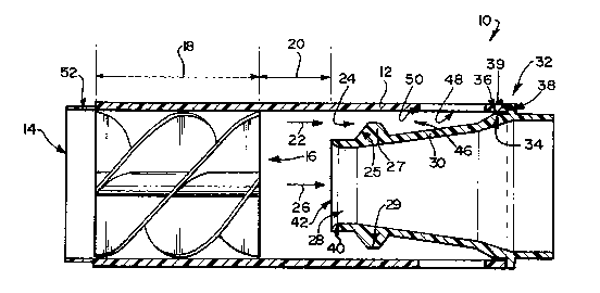
With reference to Figure 1 of the drawings, a vortex
tube gas cleaning device in accordance with the invention is
generally indicated by reference numeral 10.
The device 10 has an outer tube 12 of round cylindrical
shape having an inlet 14 at one end which will be an upstream end
in use.
Closely spaced downstream of the inlet 14, it has a
vortex generator generally indicated by reference numeral 16
positioned in a vortex generating region 18.
Downstream of the vortex generating region 18, there
is defined a separation region 20. In use, flow through the
device 10 is divided in the separation region 20 into a
peripherally outward scavenge flow stream 22 and a central or
main flow stream 26.
Downstream of the separation region 20, there is
defined a peripherally outward scavenge region 24 into which the
scavenge flow stream 22 is directed. The scavenge flowstream is
.
.. ~ ; . -
~327~
contracted toward an annular scavenge orifice 29, as will be
described hereinafter.
Concentrically inward of the scavenge region 24, there
is provided a central or main outlet region 28 into which the
main flow stream 26 is directed in use.
The scavenge region 24 and the central outlet region
28 are separated by means of an inner extraction tube 30 having
an inlet defined by a leading edge ~2 of a central orifice 40 at
the downstream end of the separation region 20. The extraction
tube 30 diverges generally outwardly to meet the outer tube 12
and to be mounted to the outer tube 12 at a predetermined
mounting position generally indicated by reference numeral 32.
At the position 32, the inner tube 30 defines a concentric spigot
formation 34 which may be slightly taper if desired. Further at
the position 32, the inner periphery toward the downstream end
of the outer tube 12 forms a concentric socket 36. The spigot
formation 34 seats snugly, concentrically, in the socket 36. A
shoulder 38 on a peripheral flange on the extraction tube 30
immediately downstream of the spigot formation 34, and a
downstream end face 39 of the outer tube immediately downstream
of the socket 36, form checking formations which inter-abut to
locate the inner tube axially in relation to the outer tube.
Thus, by means of the connecting formations 34 and 36,
the inner tube 30 is stabilized relative to and concentrically
pos,itioned or centred relative to the outer tube 12, canti-lever
fashion. Thus, the inlet to the peripheral outlet region 24 is
defined concentrically about the leading end of the inner tube
30. The inlet forms part of a continuous annular flow passage.
The significance of the annular flow passage's being continuous
is explained below.
.
Downstream of said inlet, a peripheral ring 27 having
an oblique leading face 25 protrudes into the annular flow
passage. The crown of the ring and the inner periphery of the
~ ,,.' ~ . ': ~ .
` 6 13279~7
outer tube 12 form the annular scavenge orifice 29. The ring 27
is integral with the inner tube 30 and extends from an outer
periphery thereof. The oblique face 25 guides the scavenge flow
stream 22 in contracting fashion into the scavenge orifice 29.
Downstream of the scavenge orifice 29 there is defined an annular
scavenge chamber 46 within the annular scavenge region 24.
Circumferentially spaced ports 48 provided through the wall of
the outer tube 12, lead from the scavenge chamber 46 and form
circumferential outlet means for the scavenge ~low 22. Upstream
extremities 50 of the ports 40 are axially spaced a predetermined
distance downstream of the scavenge orifice which is at least 25%
of the internal diameter of the outer tube. In a preferred
embodiment, the spacing is about 30% of said internal diameter.
In use, a particle containing gas flow stream enters
the device 10 at the inlet 14. Rotating flow is generated in
the vortex region 18 which induces the particles, which will be
of higher specific gravity than the gas, to move outwardly on
account of the rotating flow. Thus, the scavenge flow stream
22 will be enriched in respect of the particles and the main flow
stream 26 will be depleted in respect of the particles.
Expressed in other words, the gas is cleaned of particles, hence
the term gas cleaning device.
The scavenge flow stream 22 enters the peripheral
outlet region 24, is contracted as it flows into the scavenge
orifice 29, and then enters the extraction chamber 46 from where
it is exhausted via the ports 48.
The particle depleted or cleaned main flow stream 26
enters the central outlet region 28 and is exhausted from there.
A device in accordance with the invention has the
advantage that rigid and positive co-axial or concentric
alignment of the extraction tube is obtained by the mounting
formations as described. Thus, the annular flow passage,
especially the scavenge orifice 29 is continuous or uninterrupted
'. ~ ' ' ' ' , , ~ " .
.
,
.
~ 1327~7
which greatly enhances the flow characteristics of the scavenge
flow stream in particular and flow through the device in general.
In this regard it is to be appreciated that flow
through the device has strong axial and rotational components.
The rotational component of the flow and the resulting
centrifugal forces on the relatively heavy particles, induce
concentration of the parti~les toward the periphery and depletion
of the particles toward the centre of the device. Thus, the
working of the device is dependant on the rotational component
of the flow. The Inventors have established that any
interruption, e.g. in the form of a spoke, detrimentally affects
the rotational component of flow. Expressed in other words, by
having the annular flow passage continuous, rotational component
of flow in the outlet region is maintained which enhances working
of the device in comparison to other devices having flow
interruptions.
.
Furthermore, the Inventors have appreciated that
rotating flow has an "upstream awareness" of flow interruptions.
Thus, if a flow interruption is present, also flow upstream of
the flow interruption is detrimentally affected. ~herefore, in
the presence of flow interruptions in the vicinity of the inlet
to the scavenge region or the orifice of the scavenge region such
as in other cleaning devices known to the Inventors, the
rotational component of flow and thus the working of the device
are detrimentally affected in the separation region.
This "upstream flow awareness" gives rise to the
limitation of having the outlet means 48 and more specifically
their upstream extremities 50 a predetermined minimum distance
downstream of the orifice 29 which is a critical flow area in the
working of the device. It has thus been found advantageous to
symmetry or continuity of flow through the annular scavenge
orifice to have the outlet port(s) for the scavenge stream
positioned a predetermined minimum distance downstream of the
!
' , ",
' ~ .
.: ,. : ,
'' ' :' ' ''; ~ '
1327~7
` 8
- annular scavenge orifice. Such minimum spacing prevents flow
interruptions such as pillars or land areas intermediate the
outlet ports from influencing the flow through the scavenge
orifice.
The Inventors have established that, because of the
complete symmetry or continuity in flow through the device on
account of this feature, reduction in the amount of particles
in the main flow stream is enhanced.
The Inventors have found, in tests with AC coarse dust,
a five- to tenfold reduction in respect of particles above 10
micro metre in the main flow stream in devices in accordance with
the invention in comparison to devices of the prior art.
In a test sample of the general configuration of Figure
1 having an outer tube inner diameter of 18 mm, a total length
of 60 mm, a vortex generating region length of 20 mm, a vortex
angle of 180 and a central orifice inner diameter of 10 mm, and
operating at a total pressure drop of 3.8 inch standard water
gauge (about 0,96 kPa) and an air mass flow of 4,4 gram per
second in the main flow stream 26, a total mass efficiency of
dust removal of about 98% was obtained for AC coarse dust and
operating at a scavenge flow of between about 6% and 14%,
generally about 10%. ~he mass efficiency of removal of particles
larger than 10 micrometer was 99.7%. It is to be appreciated
that the larger portions are particularly detrimental to abrasion
or errosion. Thus the good separation of large particles is
significant.
With reference to Figure 2 of the drawings, another
embodiment of a gas cleaning device in accordance with the
invention is generally indicated by reference numeral 110. The
device 110 is generally similar to the device 10 of Figure 1, and
like reference numerals refer to like features. The device 110
is not described in detail. Two differences of the device llo
to the device 10 are highlighted.
. . : . . ;:. : .
1327~
g
Whereas the device 10 has a parallel outer periphery
which is conducive to a high packing density when the devices are
used in a battery or an array, the outer diameter of the device
110 increases toward its downstream end. The increase in
diameter is effected by means of a first divergence in the outer
round tube 112 as indicated by angle 113. The diverging portion
of the tube is indicated by 112.1 and extends through the
separation region 120 and beyond, up to the axial position of the
annular orifice 129.
lo The increase in diameter is further effected by means
of a second divergence or diffuser region immediately downstream
of the first divergence. The diffuser region is bounded by a
diffuser wall portion 112.2.
The angle 113 is typically about 5, i.e. the included
angle of the first divergence is typically 10.
The included angle of the diffuser region 112.2 may be
between about 20 and about 50, conveniently about 30.
The second difference is that, whereas the device 10
has a plurality of circumferentially spaced outlet parts 48, the
device 110 has a single, continuous outlet part 148 including an
angle of about 120.
Although the Applicant does not wish to be bound by
theory, it is believed that the rotational component of flow in
the outer peripheral region is better maintained with the outlet
means configuration of Figure 2.
Tests have shown that, especially in the event of a
"cut" of 100~, i.e. substantially no flow through the peripheral
outlet region, the particles nevertheless have a substantial
rotational velocity component which can be maintained to a large
.. , :
: ,
.
. . ~
~ 13279~7
'- 10
extent in the outlet means configuration of ~igure 2, which is
conducive to a good separating efficiency.
In a test sample of the general configuration of Figure
2, having an included angle of divergence of 7~, an outer tube
inner diameter of 18 mm, a total length of 60 mm, a vortex
generating region length of 20 mm, a vortex angle of 180 and a
central orifice inner diameter of 10 mm, and operating at a total
pressure drop of 4 inch standard water gauge (about l ~Pa) and
an air mass flow of 4,6 gram per second, a total mass efficiency
of dust removal of about 97% was obtained for AC coarse dust and
operating at a 100~ cut, i.e. no scavenge flow.
For the same sample, and operating at 90% cut, the
total pressure drop was 4 inch standard water gauge (about 1
kPa), the air mass flow was 4,6 gram per second in the main flow
stream, and the separation efficiency was more than 98%.
Both tests were done with AC coarse dust.
The Inventors have made inventive contributions to a
number of aspects of separating devices of the kind to which this
invention relates. The instant invention emphasises one such
aspect namely the provision of continuous flow in the outer
peripheral region. It is to be appreciated that the feature of
the current invention, together with features emphasized in co-
pending app?ications by the same inventors, give rise to a number
of advantages. Herebelow, those advantages to which the current
invention contribute substantially, are highlighted. It is to
be appreciated that the feature of the current invention in
isolation, is not the sole factor in the advantages mentioned.
An important advantage of devices of the invention is
the increased separation efficiency in relation to other, known
devices.
.
, . ' ' , : ' '
, - : . : .:. :
-~ i327~7
- 11
In respect of relatively small devices of nominal
diameters in the region of about 18 mm, and generally of the
- configuration cf- Figure 1, tests were conducted using
- standardized particle concentrations under conditions simulating
adverse operating conditions for turbines such as in aircraft,
e.g. helicopters. Currently available separating devices, and
which are used in turbines of the kind described, yielded
particle removal values of about 95% at best i.e. in terms of the
particular tests, 5~ or more of the particles remained in the
lo intake airstream of the turbines. In contrast, separating
devices in accordance with the invention yielded particle
removing rates of 97% to 98% i.e. only about 3% to 2% of
particles remaining in the inlet stream.
The significance of separation efficiency can be
appreciated if the effect of separation efficiency on the life
expectancy of blades of large turbines is considered.
If the separation efficiency of the inlet system
increases from 94% to 95%, the life expectancy is doubled, and
if the efficiency then increases to 97%, the life expectancy is
doubled again. Thus, by increasing the efficiency of 94%
currently obtainable to 97% (obtainable by devices of the
invention) the life expectancy increases by a factor 4.
In certain anti air pollution applications utilizing
industrial cyclones, particle removal efficiencies investigated
by the Applicant vary between about 30% and about 50%. A major
contributing factor to such bad performance, is the unsuitability
of cyclones for the specific applications. Under the same
conditions, and utilizing separating devices in accordance with
the invention, generally the device of Figure 2 and having
nominal inlet diameters typically of about 100 mm, particle
removal efficiencies of between about 80% and about 90% were
obtained. Expressed in other words, the degree of air pollution
on account of particles was only about 30% (worst cases) or 20%
, .
,
... .
~7~
-- 12
(best cases) of the air pollution in the case of conventional
devices.
Furthermore, it was found that devices in accordance
with the invention were more effective than conventional cyclones
in removing particles smaller than 7 micro-metre. This is of
particular importance when it is borne in mind that a human's
natural protection against particles, such as nasal hairs,
deteriorates significantly against particles smaller than 7
micro-metre. Furthermore, alveoli in human lungs typically have
cross sections of about 7 micro-metre, and are thus particularly
vulnerable to particles smaller than 7 micro-metre.
Separation devices in accordance with the invention
have been found to be superior to conventional cyclones in
removing particles of relatively low density.
A second major advantage of the invention lies in a
wide operating range. The Inventors have found that the absence
of flow interruptions in the peripheral outlet region is
conducive to flow stability. This is, inter alia, beneficial in
applications requiring a wide operating range in terms of flow
capacity and operating pressures. Thus, separating devices in
accordance with the invention of small nominal diameter (18 mm)
have been found to have wider operating ranges for a given
minimum separation efficiency than known devices tested by the
Inventors.
A further major advantage is that separating devices,
especially devices generally like the embodiment of Figure 2 for
use in industrial applications, can be used under conditions of
100% cut i.e. substantially no gas flow in the peripheral outlet
region. This allows treatment of the scavenge stream to be
greatly simplified because merely the particles need to be
removed as there is no gas flow stream to treat.
.. , ~
. . ...... .
1327~7
13
It has also been found a major advantage in respect of
separating device suitable for anti-pollution applications that
they are more compact than conventional cyclones.
. .