Sélection de la langue

Search

Sommaire du brevet 1329178 

Énoncé de désistement de responsabilité concernant l'information provenant de tiers

Une partie des informations de ce site Web a été fournie par des sources externes. Le gouvernement du Canada n'assume aucune responsabilité concernant la précision, l'actualité ou la fiabilité des informations fournies par les sources externes. Les utilisateurs qui désirent employer cette information devraient consulter directement la source des informations. Le contenu fourni par les sources externes n'est pas assujetti aux exigences sur les langues officielles, la protection des renseignements personnels et l'accessibilité.

Disponibilité de l'Abrégé et des Revendications

L'apparition de différences dans le texte et l'image des Revendications et de l'Abrégé dépend du moment auquel le document est publié. Les textes des Revendications et de l'Abrégé sont affichés :

  • lorsque la demande peut être examinée par le public;
  • lorsque le brevet est émis (délivrance).
(12) Brevet: (11) CA 1329178
(21) Numéro de la demande: 1329178
(54) Titre français: FONTAINE A COLORANTS
(54) Titre anglais: PAINT TONING MACHINE
Statut: Périmé et au-delà du délai pour l’annulation
Données bibliographiques
(51) Classification internationale des brevets (CIB):
  • B44D 03/00 (2006.01)
  • B44D 03/08 (2006.01)
  • B65D 88/54 (2006.01)
(72) Inventeurs :
  • TAMMI, ANSSI (Finlande)
(73) Titulaires :
  • CIMCORP OY
(71) Demandeurs :
  • CIMCORP OY (Finlande)
(74) Agent: NORTON ROSE FULBRIGHT CANADA LLP/S.E.N.C.R.L., S.R.L.
(74) Co-agent:
(45) Délivré: 1994-05-03
(22) Date de dépôt: 1988-03-21
Licence disponible: S.O.
Cédé au domaine public: S.O.
(25) Langue des documents déposés: Anglais

Traité de coopération en matière de brevets (PCT): Non

(30) Données de priorité de la demande:
Numéro de la demande Pays / territoire Date
871,239 (Finlande) 1987-03-20

Abrégés

Abrégé anglais


Abstract
A paint toning machine comprising a plurality
of colour paste containers (1), and a pump (2) for
each colour paste container (1) for pumping colour
paste from the container for the dispensing or circu-
lation thereof. For the elimination of the problems
caused by leaks occurring in the colour paste
dispensing pump and the connections of the colour
paste suction and feeding conduits thereof, the pump
(2) according to the invention is arranged in the
paste container (1) in the vicinity of a bottom (4)
thereof essentially below the surface of the colour
paste (3) contained in the container.
(Figure 1)

Revendications

Note : Les revendications sont présentées dans la langue officielle dans laquelle elles ont été soumises.


- 5 -
The embodiments of the invention in which an
exclusive property or privilege is claimed are defined
as follows:
1. A paint toner dispensing machine for
dispensing solvent-diluted color pastes in particular,
comprising:
at least one paste container having a bottom
and a side wall and provided with
a cover preventing the evaporation of the
solvent of the color paste;
a gear-type color paste pump for pumping
paste for the selective dispensing or circulation
thereof and comprising a drive shaft which is led
through the cover of the container;
a dispensing valve located within the
container for the dispensing of the color paste; and
a floor positioned above said bottom;
said pump being arranged completely within
the paste container between the bottom thereof and said
floor essentially below the surface of the color paste
when the color paste is contained in the container,
said floor forming together with said bottom there-
between a suction conduit, pressure conduit, return
conduit and dispensing conduit for the pump, all within
the container; and
said pressure conduit being by means of said
dispensing valve selectively connectable within the
container either to the return conduit or the
dispensing conduit.

Description

Note : Les descriptions sont présentées dans la langue officielle dans laquelle elles ont été soumises.

-
~\
~L32g~ 7~
A paint toning machine
This invention relates to a paint toning
machine for dispensing solvent-diluted colour pastes
in particular, comprising a plurality of paste con-
tainers provided with a cover preventing ~he evapor-
ation of the solvent of the colou:r paste, and a plu-
rality of colour paste pumps for pumping paste for the
dispensing or circulation thereofl each colour paste
container comprising one pump.
A paint toning machine of the above type is
known e.g. from Australian Patent Specification
162 212. In the paint toning machine of thi.s publica-
tion, the dispensing and circulating pump for the col--
our paste is a gear-type pump positioned outside the
colour paste container and connected both to the col-
our paste container and to a dispensing nozzle by
means of hose connections. However, there always
exists a risk of leaks in this kind of arrangement,
because the hose connections both on the suction and
delivery side of the pump are positioned in an open
space. In addition, the pump itself has to be encased
tightly. This is especially important when solvent-di-
luted colour pastes are used, as the solvents very
easily penetrate through the seals, which causes the
colour paste to be hardened and the pipe connections
to be clogged. ~urther, when coming into contact with
the seals solvents tend to make the seals inelastic,
which can lead to leaks and even to jamming of the
drive shaft of the pump. ~he biggest problem with
leaks, however, is the risk of explosion because the
used solvents are very inflammable.
The object of the present invention is to pro-
j vide a paint toning machine in which the above prob-
lems are essentially eliminated. This is achieved by
~. .
,'' ~,
,
.
.

- 2 - 1329~78
means of a paint toning machine according to the inven-
tion, which is characterized in that there is at least
one paste container having a bottom and a side wall and
provided with a cover preventing the evaporation of the
solvent of the color paste; a gear-type color paste
pump for pumping paste for the selective dispensing or
circulation thereof and comprising a drive shaft which
is led through the cover of the container; a dispensing
valve located within the container for the dispensing
of the color paste; and a floor positioned above the
bottom; the pump being arranged completely within the
paste container between the bottom thereof ~nd the
floor es~entially below the surface of the color paste
when the color paste is contained in the container, the
floor forming together with the bottom therebetween a
1 suction conduit, pressure conduit, return conduit and
;3 dispensing conduit for the pump, all within the con-
tainer; and the pressure conduit being by means o the
dispensing valve selectively connectable within the
container either to the return conduit or the dispens-
¦ ing conduit. More specifically, each pump is arranged
in its paste container in the vicinity of a bottom
thereof essentially below the surface of the color
paste contained in the container and comprises a drive
shaft which is led through the cover of the container
through a gas-tight through hole. As the pump is so
immersed in the color paste, neither the pump itself
nor the connections of the suction and pressure con-
duits of the pump need be absolutely gas-tight. Since
it is possible to construct the paste container into an
`~! essentially closed space wherefrom the drive shaft of
the pump and possibly also a dispensing hose project
through gas-tight through holes, possible leaks in the
pump or the pipe connections thereof cannot have the
above-mentioned adverse effects.
In the following, the paint toning machine
~, according to the invention will be described in more
,
",
~ .
.

- 2a - ~329178
detail with reference to the attached drawings,
wherein:
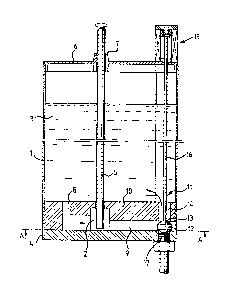
Figure 1 is a cross-sectional side view of
one paste container of the paint toning machine
according to the invention; and
Figure 2 is a cross-sect.ional view of the
~ paste container of Figure 1 along the line A-A in
i, Figure 1.
Figure 1 shows one of a plurality of paste
containers comprised in the paint toning machine
according to the invention; this container is indicated
with the reference numeral 1. A gear-type pump 2 is
immersed in the color paste contained in the paste con-
rl~ tainer, and a drive shaft 5 of the pump is led through
;1 a cover 6 of the container through a gas-tight through
hole 7. The cover 6 of the container is arranged on
the container 1 as tightly as possible. In the
i embodiment of the invention shown in Figure 1, the pump
as
,:
. :
,~
,'. ~
,
.
. ~ .
:"
" ' ~ :
... ~. ~ ' ~ ' ,. ' 1,
.,~ , . . .. .
,: . , : -'~ ' '
: ~ ,

\
~329178
such is not encased separately in such a manner that
it would comprise pipe connections for suction and
pressure conduits; instead, suction and pressure con-
duits 8 and 9 are formed by means of a floor 1~ posi-
tioned above a container bottom 4. The floor 10 also
forms a structural part of a dispensing valve 11 at-
tached to the colour paste container 1 in such a man-
ner that it forms a sea-t for an upper conical surface
13 of a spindle 12 of the dispensing valve 11. When
the valve 11 is in the position shown in Figure 1 and
the pump 2 is on, the paste 3 flows as shown by the
dark arrows in the figure in such a manner that it is
sucked through the suction conduit 8 into the pump 2,
and it leaves the pump through the pressure conduit 9
and a return conduit 14 going through the floor 10,
and returns to the paste container. In this way, the
colour paste can be circulated and mixed in the
container. When the spindle 12 of the valve 11 is
lifted to its upper position by means of a valve oper-
ating means 15 positioned on the cover 6 and a valve
drive shaft 16, a dispensing outlet of the pressure
conduit is opened through the bottom 4 of the contain-
er 1 via a conduit 17 to a colour paste dispensing
nozzle (not shown).
Figure 2 shows a section of the colour paste
container of Figure 1 along the line A-A shown in
Figure 1. Tt appears from Figure 2 that the pump 2 is
a gear-type pump comprising a pximary gearwheel 18 at-
tached to the drive shaft 5 and a secondary gearwheel
attached to a support shaft 19. As is to be seen in
Figure 2, the colour paste container 1 is essentially
round in shape with the exception of the projection
formed for the dispensing valve.
~ he paint toning machine according to the in-
vention and especially the dispensing pump i~mersed in
,; .
'
,: . . . . .
.
.
,

1329178
the colour paste contained in the paste container have
been described above only by way of example by means
of one specific embodiment. It is to be understood
that $he idea according to the invention of immersing
the dispensing pump in the colour paste could be real-
ized also by a conventional dispensing pump. As this
pump and the pipe connections thereof would also be
wholly immersed in the colour paste, the same advan-
tages as described above can be achieved in this case,
too, concerning leaks in the pump itself or the con-
nectlons thereof.
'
.
r'
.1
~ '
~, ~
'1, '
,
''.1 ' ' ` ' '

Dessin représentatif
Une figure unique qui représente un dessin illustrant l'invention.
États administratifs

2024-08-01 : Dans le cadre de la transition vers les Brevets de nouvelle génération (BNG), la base de données sur les brevets canadiens (BDBC) contient désormais un Historique d'événement plus détaillé, qui reproduit le Journal des événements de notre nouvelle solution interne.

Veuillez noter que les événements débutant par « Inactive : » se réfèrent à des événements qui ne sont plus utilisés dans notre nouvelle solution interne.

Pour une meilleure compréhension de l'état de la demande ou brevet qui figure sur cette page, la rubrique Mise en garde , et les descriptions de Brevet , Historique d'événement , Taxes périodiques et Historique des paiements devraient être consultées.

Historique d'événement

Description Date
Inactive : CIB expirée 2022-01-01
Inactive : CIB de MCD 2006-03-11
Le délai pour l'annulation est expiré 2003-05-05
Lettre envoyée 2002-05-03
Inactive : Demande ad hoc documentée 1998-05-03
Lettre envoyée 1997-05-05
Accordé par délivrance 1994-05-03

Historique d'abandonnement

Il n'y a pas d'historique d'abandonnement

Historique des taxes

Type de taxes Anniversaire Échéance Date payée
TM (catégorie 1, 4e anniv.) - générale 1998-05-04 1998-04-21
TM (catégorie 1, 5e anniv.) - générale 1999-05-03 1999-04-19
TM (catégorie 1, 6e anniv.) - générale 2000-05-03 2000-04-25
TM (catégorie 1, 7e anniv.) - générale 2001-05-03 2001-04-09
Titulaires au dossier

Les titulaires actuels et antérieures au dossier sont affichés en ordre alphabétique.

Titulaires actuels au dossier
CIMCORP OY
Titulaires antérieures au dossier
ANSSI TAMMI
Les propriétaires antérieurs qui ne figurent pas dans la liste des « Propriétaires au dossier » apparaîtront dans d'autres documents au dossier.
Documents

Pour visionner les fichiers sélectionnés, entrer le code reCAPTCHA :


Pour visualiser une image, cliquer sur un lien dans la colonne description du document. Pour télécharger l'image (les images), cliquer l'une ou plusieurs cases à cocher dans la première colonne et ensuite cliquer sur le bouton "Télécharger sélection en format PDF (archive Zip)" ou le bouton "Télécharger sélection (en un fichier PDF fusionné)".

Liste des documents de brevet publiés et non publiés sur la BDBC .

Si vous avez des difficultés à accéder au contenu, veuillez communiquer avec le Centre de services à la clientèle au 1-866-997-1936, ou envoyer un courriel au Centre de service à la clientèle de l'OPIC.


Description du
Document 
Date
(aaaa-mm-jj) 
Nombre de pages   Taille de l'image (Ko) 
Abrégé 1994-07-19 1 19
Revendications 1994-07-19 1 37
Dessins 1994-07-19 1 37
Description 1994-07-19 5 189
Dessin représentatif 2002-01-10 1 12
Avis concernant la taxe de maintien 2002-06-02 1 179
Taxes 1997-04-15 1 66
Taxes 1996-04-18 1 54
Correspondance reliée au PCT 1994-01-26 1 18
Demande de l'examinateur 1991-12-04 1 40
Demande de l'examinateur 1993-08-03 2 56
Correspondance de la poursuite 1993-11-02 2 32
Correspondance de la poursuite 1992-03-26 2 31