Note : Les descriptions sont présentées dans la langue officielle dans laquelle elles ont été soumises.
~32972~
DIAPHRAGM PUMP
ACKGROUND OF THE INVENT~ON
Double-diaphragm air-operated pumps are in general well
known. Such pumps are generally well-suited for transferring materials out
of drums or other bulk storage units to another location. Such pumps should
be easily and ine~pensively manufactured, easily serviced and compatible
with a large variety of materials as well as having long service life. While
diaphragms have been forrned of materials having ridges thereon, such
construction inevitably leads to the increased use of material in return for thedesired service life. It is therefore an object of this invention to provide a
diaphragm pump which is easily serviced, inexpensively manufactured, and
yet provides excellent service life.
.
SUMMARY OF THE II~T~IENTION
A double-diaphragm air-operated pump is designed to be
molded primarily from plastic for light weight, chemical compatibility and
manufacturability reasons. The pump is designed so that the four check
j valves are easily removable by simply unthreading a plug and lifting out the
-! ~ pieces needed to be cleaned or otherwise serviced. A removable seat holds
.,- the ball and in turn is held in place by a wire cage which is in turn held in
place by the threaded plug.
The air valve on the pump has a relatively conventional spool,
having sections at either end with first and second diameters and a
,, -1- ~
~ '
: . : , , - .. ,, ~ . :.:
'
...
~3297~9
transitional area connecting them. A U-cup is located in the
housing of the air valve and the open side of the U-cup faces the
larger of the two diameters such that when the transition area
first contacts the seal, it is contacting the open end of the U
rather than the closed end as is traditional in conventional
practice.
The diaphragms that are used in the pump can be formed
of a plastic material such as DuPont's Teflon* and are generally
conical in shape and have an angle of elevation. The plurality
of convolutions are disposed on either side of the angle of
elevation and the diaphragm is formed of a generally uniform
thickness of material. This construction leads to greatly
increased service life while minimizing the material needed for
molding.
The inlet pipe extends generally downwardly from the
base of the pump and passes through a bung having an offset
aperture therein. The aperture seals against the inlet pipe and
by rotatably positioning the bung plug within the bung hole, the
` pump may be tightly located against the rim of the drum or other
, 20 container from which material is being pumped. The feet of the
"
~ pump are radiused so as to snugly, comfortably fit against the
:
il rims of commonly used drums.
,,
*trade mark
,,~.. .
,, ~ ,.i
,... ..
:
::
~ 32972~
In accordance with one aspect of the invention there
is provided a pump for mounting on a drum having a rim and an
opening, said pump comprising: a housing; at least two feet
depending downwardly from said housing, said feet being radiused
to securely fit within said rim; an inlet tube depending
downwardly from said housing; and a bung plug threadedly
engageable with said opening and comprising an aperture in said
bung plug offset from the centering thereof, said aperture
. including means to snugly grip and seal said inlet tube whereby
: 10 said pump can be securely positioned against said rim by rotating
said bung plug so as to position said feet against said rim.
.,
These and other objects and advantages of the invention
will appear more fully from the following description made in
conjunction with the accompanying drawings wherein like reference
characters refer to the same or similar parts throughout the
several views.
~i
. ~,
;~
;
.. ~ .
::~ 2a
'~ ~
. . .
~ . !
~3297~9
A BRIEF DESCRIPTION O~: THE DRAWINGS
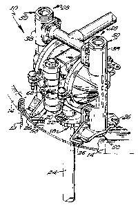
Figure 1 is a perspective view showing the pump of the instant
invention mounted on a drum.
,
,.
Figure 2 is a front plan view of the device of the instant
invention.
Figure 3 is an end plan view of the device of the instant
inventi on.
Figure 4 is a sectional view taken along Line 4-4 of Figure 3.
Figure 5 is a sectional view taken along Line 5-5 of Figure 2.
.,
: ~ Figure 6 is a sectional view taken along Line 6-6 of Figure 3.
:-^
Figure 7 is a sectional view taken along Line 7-7 of Figure 6.
:-1
::1
. `
Figure 8 is a perspective view of the bung plug of the instant
invention.
, .,
~.
,
;~~
~ - 3 -
.,
,,
. . ,
,
.:. . . . . .:
- : . : .- -
" " ,, ' :, ' ~ ,
. ~
--.
132~729
DESCRIPTION OF rHE Pr~EFERRED EMBODIMENT
The pump 10 of the instant invention is shown generally in
Figure 1 on top of a drum 12 having a rim 14 and a bung hole 16 therein. A
bung plug 18, also part of the instant invention, may be screwably located into
aperture 16 and is comprised of an off-center aperture 20 located therein
having sealing means 22 in the form of resilient lips which are capable of
gripping an inlet pipe 24 which extends downwardly from pump 10. By
rotatably positioning bung plug 18 and aperture 16, pump 10 may be
~,. .
positioned against rim 14 such that feet 26 are snugly positioned against
rim 14, thereby securely locating pump 10 relative to drum 12. This
relationship is also shown in Figures 6 and 7 and details of the bung plug are
shown in Figure 8.
In general, double-diaphragm pump 10 is conventional in
nature and generally well-known with the exception of those features
explicitly discussed herein. The pump is designed to be particularly suited for
molding from a plastic material. Toward that end several features may be
incorporated therein. In particular, the check valves 28 are shown in
particular detail in Figures 4 and 6. In particular, a first passageway 30
connects with the pumping chamber 32. Located in first passageway 30 is a
ball cage 34 which rests on a step 36 in the outer housing 38 of pump 10.
Cage 34 has an inner bore which is sized to receive check ball 40. Seals 42
assure that nothing will leak around the check valve assembly 28. A
perforated plate 44 lies on top of ball cage 34 and retains ball 40 in position. A
second passageway 46 intersects first passageway 30 and at the intersection
: . . . . .
~ 32972~
~hereof, a cage member 48 serves to allow fluid passage at the junction of the two
passageways and yet causes the retention of perforated plate 44 and ball cage 34 in place.
Cage 38 is held in place by a threadably plug 50 which is threaded into position in
housing 38 by means of threads 52. Thus, when it is desired to service or replace the
check valve assembly 28, plug 50 is simply unscrewed, cage 48 removed and perforated
plate 44 and cage 34 removed along with check ball 40. Where necessary the
components may be replaced, cleaned or otherwise serviced. This is in distinction from
current diaphragm pump practice which requires substantial disassembly of the pump in
order to get at the check valves. Of course, reassembly takes place in the opposite
sequence.
; The cliaphragm 54 is shown in Figure 6 and is generally conical in shape
~: .
and has an angle of elevation (not shown) on which are disposed on either side a
plurality of convolutions 56. Diaphragm 54 is formed from a generally planar sheet of
rnaterial having substantially equal thickness across the surface thereof.
,
~,,
. ~ .
~/ The air valve 58 is shown in detail in Figure 5. Air valve 58 is initially
-,~
operated by a pilot valve (not shown). Such a pilvt vah~e may be of any conventional
~ i
type as is well-known in the art and provides signals through pilot ports 60 in housing 62.
, .
Housing 62 is also provided with ports 64, 66, 68, 70 and 72. Port 68 is connected to a
. source of pressurized air which will operate the pump. Ports 64 and 72 are both
. .,
-~ connected ~o ~he exhaust which may be a muffler such as that shown a$ 74 in Figure 3.
~ Ports 66 and 70 are connected respectively to the air side of diaphragms 54 in A and B
".. . ~
` air chambers 76 and 78 respectively. Thus, as shown in Figure 5, port 70 is
-5 -
~`
~l32~7~9
connected with port 72, thereby exhausting the B side 78 of pump 10.
Similarly, the A side 76 through port 66 is pressurized by pressurized air from
passageway 68. As spool 80 shifts downwardly from the position shown in
Figure 5, the converse connection will take place with ports 68 and 70
connected and ports 64 and 66 connected. In particular, spool ~0 has at two
locations a first larger diameter ~2 and a second smaller diameter 84
connected by a transition area 86. U-cup seals are located in the housing 62
and face towards the center port 68 of air valve 58. That is, when contacting
the transition S6, each seal 88 faces the first larger diameter ~2. This
construction provides an effective long-life sealing mechanism and yet .:, in
contrast to the norm used in the art wherein such seals are generally located
in the opposite direction from that shown.
It is contemplated that various changes and modifications may
be made to the diaphragm pump without departing from the spirit and scope
of the invention as defined by the following claims.
.
, ;~ .
,,
.~
-6 -
`~: ' . ' ' ,
.