Note : Les descriptions sont présentées dans la langue officielle dans laquelle elles ont été soumises.
1 32993~
-- 3 --
FIELD OF THE INVBNTION
The invention relates to bearings and more particularly to
bearings of the type suitable for supporting machinery, plant
and other loads relative to a base structure to protect the load
against horizontal shear forces.
BACKGROUND TO THE INVENTION
At present in a number of industries and situations there
are advantages to be gained from mounting plant and machinery on
a bearing or bearings so that in, for example, earthguake
situations any horizontal shear forces created are to an extent
absorbed to therefore minimize the likelihood of damage to the
plant or machinery.
An object of the present invention is to provide a bearing
for plant or machinery which bearing is capable of absorbing to
a large extent horizontal shear forces.
Further objects and advantages of the present invsntion
will become apparent from the following description which is
given by way of example only.
SUMMARY OF THE INVENTION
According to one aspect of the invention there is provided
a high stability structural bearing for placement between members
of a structure, the bearing comprising a plurality of adjacent
metal stiffening plates constructed from a planar, stiff and
rigid material, each plate having a plurality of discrete,
spaced-apart resilient disc shaped bearings on a surface thereof
abutting a surface of an adjacent plate, the stiffening plates
and the disc shaped bearings providing a layered bearing assembly
.
.
'-`` 1 32~93q
in which the disc shaped bearings of adjacent plates provide
generally columnar resilient bearings stiffened by the metal
plates to form a stable bearing unit for protecting members of
the structure against horizontal shear forces, said bearing
further including energy absorbing components between the
adjacent plates so that the components are cleform~d by shear
movement between the plates, the components absorbing energy
being steel, lead or a polymeric material of moderate viscosity
trapped between rubber rings bonded to the plates; each plate or
assembly of the plurality of adjacent plates having a skirt which
protects against ingress of deleterious matter to spaces between
adjacent plates; and each plate being formed in two parts and
being integral with or attached to adjacent plates above or
below, and being constructed from a synthetic or natural rubber
material having a shor~ hardness in the range of above 30 to 80.
According to a second aspect of the invention there is
provided a high stability structural bearing for placement
between members of a structure, the bearing comprising a
plurality of adjacent metal stiffening plates constructed from
a planar, stiff and rigid material, each plate having a plurality
of discrete, spaced-apart resilient disc shaped bearings on a
surface thereof abutting a sur~ace of an adjacent plate, the
stiffening plates and the disc shaped bearings providing a
layered bearing assembly in which the disc shaped bearings of
adjacent plates provide generally columnar resilient bearings
stiffened by the metal plates to form a stable bearinq unit for
protecting members of the structure against horizontal shear
B
.
.. . . ~ '' , '
.
- 4a - 1 329939
forces, said bearing further including energy absorbing
components between the adjacent plates which provide damping
therewithin; each plate or assembly of the plurality of adjacent
plates having a skirt which protects against ingress of
delet~rious matter to spaces between adjacent plates; and each
plate being formed in two parts and being integral with or
attached to adjacent plates above or below, and being constructed
from a synthetic or natural rubber material having a shore
hardness in the range of about 30 to 80.
B
. . .
-~ ~ 5 ~ 1 329q 39
Further aspects of the invention which should he
considered in ail its novel aspects will become apparent
from the follawing descriptions which are given by way of
example only.
BRIEF~DESRIPTION~QF~T~E~DR~WIN5S
Figure 1 shows a perspective view from beiow of one
example of plate usa~le in a bearing assembly
according to the invention
Figure 2 shows a side view of a bearing assembly built
from a plurality of plates of the type shown in Figure
Figure 3 shows a sectional ~iew of an alternative
construc~ion of bearing assembly according to the
invention which includes a peripheral skirt
Figure 4 shows a ta~le indicating details of example
of bearing for which Figures 5 to 18 give the
characteristics thereof
Figure 19 shows a sectional view of part of a bearing
assembly which includes the provision of damping
~,
'
,
. .
.' ' ' :.' '
. - - 6 ~ 1329q39
Figure 20 shows a sectional view of the damping region
which is indicated by arrows A-A in Figure 19.
DES ~
Embodiments of bearing according to the present
invention will now be described with reference to the
accompanying drawings and an example of specific use. The
embodiment of bearing assembly shown in Figures 1 ~nd 2 is
one of a series of similar bearing assemblies designed for
placement beneath a generator, transformer or the like i~em
of electrical machinery forming part of an el~ctricity
supply system.
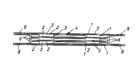
The bearing assembly shown in Figures 1 and 2 consists
of a series of similar bearing plates an example o one of
which is ~hown in detail fro~ below in Figure 1. Each
bearing plate 1 consis~s of a planar member 2.
The planar member 2 has either on its surface or lower
surface three or four disc shaped beari~gs. In Figure 1 the
bearing plate 1 incorporates ~our discs 3 on its lower
surf ace 4 .
The plate 1 can be constructed f rom any suitably stiff
material~ for example stainless s~eel or a ric~id rubber
material.
The discs 3 are bonded to or formed integrally with
the surface(s) of the plate 1.
The disc shaped bearings 3 are manufactured from a
synthetic or natural rubber material which has a shore
hardness of b~ween 30 to 80. This theoretically allows for
~! ` ` . . .; , . ;
' , ~
. ~ ~ " ' ' '' ,
- t -I 329939
a deflec~ion of up to 200% of the rubber thickness as a
horizontal displacement.
As is shown in Figure 2 an assembly of similar plates
1 with upper and a lower surfaces 4, 5 respectively are
mounted together by bonding the dlscs 3 to adjacent plate3~
The lower plate 5 has a series of bolt ho:Les 8 for mountiDg
the plate S of the bearing asse~bly to a foundatien. The
upper plate 4 also includes similar mounting holes 9 around
its periphery. The ~ounting holes 9 are suitably positioned
for mounting an item of machinery or a load thsreon~
The aligned and bonded discs 3 form spaced apar~
columnar bearings which in practice are relatively tali
which would normally have inherent stability problems~ The
stability problem is substantially eliminated by the plates
which tie and stiffen the assembly to form a stable bearing
assembly uni~
Advantageously as shown in ~igure 1 the periphery of
each p~ate 1 has a skirt 6 downwardly depcnding ~herefrom.
The provision of the skirt 6 has advantages o~her than
kaeping deleterious ma~erial from between adjacent plates 1,
1'. The skirt when the bearing assembly is absorbing a
horizontal shear force tends to act as a damper because of
its frictional contact with the plate therebeneath.
An alternative construction is shown in Figure 3 in
which the skirt~ 6 are replaced by a ~ingle peripheral skirt
7 which surround the comple~e bearing asse~bly~
In use a required number of bearing assemblies are
,
.:
: .
, : ' ' ~ .
, . :
~ 8 - ' 1 329~39
mounted on foundations and the overall size and
characteristics the indi~idual bearings is selected to suit
the load to be supported thereon and the degree of
protection required.
A range of bearings incorporating the invention are
described in Pigure 4 to 18. The range is not all inclusive
but shows ~he wide variety of configurations available.
Details in the bearings of table are ~hown in Figure 4 are
detailed in Figures 5 to 18. The bearings are manufactured
within the following constraints:
~ o. of layers - variable
Plan Size - variable
Disk diameter - variable
Disk thickness - over 8mm
Rubber hardne~s - 30 to 80 Shore A
Consideration must be given to the following when a
bearing is designed:
(1) Stability ~ overall height of the bearing
should not exceed approximate~y 2/3 of the
minimum plan dimension of the steel platesO
(2) Steel plate size - should be approximately 3.5
to 4 times the di~k diameter.
In practice the load bearing characteristics of each bearing
assembly is selected to suit a particular period of
oscillation in horizontal shear.
The test and calcula~ed recommendations shown in.
Figures 5 to 18 are for a range of bearings havi~g
- :,: , . , - . :
....... . .
` 1 32q9~9
capacities up to 20 tonnes. The recommendations incorporate
variations in rubber disc dimensions which allow for any
design requirement fo~ natural period of oscillation,
typically for most designs being in the range 1 to 3
seconds. They also allow for the requirecl design horizontal
deflection, which for mos~ ear~hquake loaclings is up to
lSOmm in any horizontal direction from the at rest position.
The use of a stiffening plate(s) linkin~ together the
columnar bearings provides improved load bearing and shear
resistant characteristics in the assembled bearing.
In Pigures 19 and 20.are shown details of a bearing
assembly with damping components. The parts of the assembly
have the same identification numerals as the be~ring shown
in Figures 1 and 2. The plates 1 are 3mm steel plates with
disc shaped bearings 3 which form a cavity 10 in the centre
of which a damping means indicated generally by arrow 11.
The da~ping means includes a cavity 12 formed by an annular
member 13 (Figure 20) in which are a serie~ of discreet
eomponents 14 spaced apart in the cavity 12. The componen~s
14 are fixed to the plates 1 and the space is filled with a
poly~eric material, for example, a silicone polymer, bitumen
having a moderate viscosity and having chaxacteristics which
absorb horizontal shear forc~s.
In use any shear forces are absorbed by the polymeric
material therefore minimising mov~ment in the bearing
asRembly.
Thus by this invention there is provided a high
1,
'
.
'
lo - ~ 32~939
stability bearing for plant or machinery which is capable of
absorbing to a large extent hoxizontal shear forces.
~ Par~icular embodiments of the invention have been
described and it is envisaged tha~ improv2ments and
modifications can take place without departing from the
scope and spirit of ~he appended claim~.
. ~ . .
.
- ~ ~, ~ . ' . --
.. . . ..