Note : Les descriptions sont présentées dans la langue officielle dans laquelle elles ont été soumises.
~332728
Emerqency stairs ~or external mountina on buil~inas
The present invention relates to emergency stairs for
mounting outside buildings, and comprising platforms at
every floor of the building and ladders~staircases between
the platforms.
A series of different emergency stair structures is known to
ensure the possibillty of evacuating higher building struc-
tures, e.g. blocks of flats, hotels, hospi~als, homes for
the aged, nursing homes, office blocks, schools, etc.
The classical design consisted of stationary ladders, e.g.
between balconies of blocks of flats or external metal
ladders on office blocks, hotels, etc. Problems in con-
nection with said known approaches were above all that
accessibility was difficult, also that the ladders o~ten
were too steep, and finally, that such ladders could also be
used to provide illegal access to a building for persons not
concerned. In order to prevent the last mentioned disad-
vantage such stationary ladders often ended at quite a
distance ~rom the ground, which resulted in ~urther
disadvantages. It was, especially, di~eicult eor elderly
people ~o escape, via the known escape devices, also from
balconies where it was necessary to o~en trapdoors and climb
down closel~ to a wall.
E~forts were made to solve these problems, e.g. by a
structure as disclosed in German Patent 23 60 634. In said
speci~ication a very comprehensive escape route system is
disclosed, which is apparently intended ~or mounting during
house building, and which comprises a series of platforms
with intermediate ladders. The platforms are intended to be
li~ted by the aid of a hoisting means and to be placed in
the shape o~ a pack on roo~ level of the house. This is a
very expensive and complicated structure which also neces-
.*
~332728
sitates special exits from the building, although it must besaid to solve the mo,st essential problems, viz. a safe and
comfortable escape route ln a critical situation, at the
same time as the escape route can be stored at such a high
level that there will be no access to the buidling, via said
route under normal circumstances. As mentioned, this will be
a most expensive structure, which requires a special design
of the buildi~g, use of special hoisting and winch means
which must be stored in a fire proof manner, and it will
also require some maintenance to ensure a state of constant
readiness. Such an escape route will, furthermore, require a
special structure of the building or buildings and it may
constitute quite a dominating factor as regards appearance.
It is an object of the present invention to provide
emergency stairs which will represent an escape rou~e as
safe as the one disclosed in DE-PS 23 60 634, but with a
considerably more simple design, which requires less
maintenance, and does not form a dominating factor of a
building when not in use. The emergency stairs should also
form a safe and very readily utilizable escape route, and it
should be safe in that, in case of an accident, a person can
only fall a short distance. It is, ~urthermore, free of ice
and snow in the cold season.
This object is achieved by emergency stairs which are
characterized by the Eeatures appearing ~rom the clalms.
By the aid of the invention, emer~ency stairi3 are provlded
whlch will sit closely ad~acen~ -to a wall o e a building when
not in u~e and wiIl, thus, be very li-ttle conspicuous, also,
they cannot be used for climbing up and, furthermore, they
will bar the entrances from single floors.
In order tc ensure said effects and to make the stairs as
inconspicuous as possible they may be provided with an
external cover, which will prevent the stairs/rungs from
being viewed in a retracted state, and prevent climbing on
3 133~728
the outside. An esential, further feature when such a cover
is used is that the staircaise will also receive a protec-
tive shield towards outside environment, which will give the
user, in case o~ an emergency, the im~ression of moving in a
closed staircase. T~e cover may also be provided with
banister means, e.g. chains, or tarpaulins or sheets, e.g.
in pockets, to cover the lateral areas as well, if it is
desirable to provide an escape staircase which is gastight
to a maximum degree.
It should be mentioned that in US-PS No. g 388 982 a device
is disclosed which might show a certain similarity with the
object o~ the present invention. The American device,
however, is a building scaffold which is mounted and secured
onto a wall during a phase of building or renovation, and
the device according to said US-PS cannot be used in the
same manner as the invention, nor can it be collapsed
towards the wall o~ the building without extensive prepara-
tory operations comprising insertion of ladders, closing of
trapdoors, etc.
The invention is disclosed in more detall below, with
reference to an embodiment which is shown in the drawings,
where
. J~
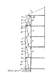
Figure 1 is a diagrammatic side elevation o~ a buildin~
with mounted escape stairs accordin~ -to -the
, lnvention;
Figure 2 shows a detailed side elevation oE a portion
o~the e~ergency s~airs as shown in Flgure l; and
Figure 3 is a dlagrammatical view of a platEorm of the
emergency stairs.
Emergency stairs according to the invention are mounted on a
building 1, which has, e.g. five floors. Access to the
emergency stairs is through openings 2, which may, e.g. be
doors at the ends of corridors, but may, if desired, also be
- / -
4 :L33272~
other kinds of openings, for instance windows or the like.
The kind o~ opening is o~ no concern to the invention.
Outside said openin~s 2 the emergency stairs according to
the invention are provided. The stairs comprise a separate
platform 3 outside each floor, and a plan view of such a
platform 3 is shown in Figure 3. The platforms are main-
tained in a horizontal position outside each floor by the
aid of hinge means 10 connecting platform 3 with the wall of
the building, and one or a plurality of interlocking means
provided on the outside of platformms 3 and consisting of
elements which are diagrammatically shown in the drawing and
indicated by numerals 5 and 6. Said interlocking means 5 and
6 may, e.g. be chains to which the platforms are attached by
links 13, or they may be other kinds of interlocking means
with articulated connections with the platforms. The only
essential ~eature in this connection is that the uppermost
securing means 5 should be retractable so that the platform
structure can be folded inwards. This can, most advan-
tageously, be obtained by a ~lexible design o~ means 5,
making them extendable by a suitable mechanism 18 to provide
a horizontal position of the platforms when starting from a
"retracted" position of the stairs, or to provide a possi-
bility o~ retraction when the stairs are to be retracted
again. From the area indlcated at 18, e.g. a rope system
extends downwards alon~ the building, on the inside or
outside, 90 that the stalrs can, lf necessary, be actuated
or ex~ended. Such a rope system is not described ln detail,
but lts design will be obvious to those skilled in -the ar-t.
Hook arran~ement la, may ~.g. comprise a sail hook, a snap
hook, o~ the llke. Automatical actuation may be arranged, i~
permitted. ~ i
Between each platform 3 a ladder or a staircase 4 is
provided ~herea~ter designated as a ladder), which is
attached by a hinge 11 at the lower side of the platform,
and which is provided with a sllde means, preferably a wheel
12, at lts lower end, so that ladder 4 can sllde or roll
~orwa~ds and backwards on the plat~orm. In a position ~or
13327~8
use the ladder will stand inclined, as illustrated in
Figures 1 and 2. The ladder 4 is attached adjacent to an
opening in the platform, and ln case of an emergency lt will
be possible to pass down through opening 16 in the platform
and climb down the ladder to the next platform 4. In order
to provide a reliable support for the ladder, and to
simplify and also secure the escape route the opening of the
next platform is displaced to the location marked 17 in
Figure 3. The ladders are, thus, alternately displaced
between platforms. The platforms and the emergency staircase
must, obviously, be provided with banisters or the like to
prevent people from falling down from the platform. A
certain protection is already achieved due to the fact that
the ladders are arranged to make users climb on the side
facing the house wall, but there will always be a certain
hazard at the point where a person climbs down through the
opening in the platform. In order to provide maximum safety
a protecting cover 7 is preferably provided outside the
emergency stairs, which will cover the stairs and form a
protection towards the outside. At the same time the
emergency stairs will be protected and covered in a
collapsed position, so that the emergency stairs will not
form a dominating factor on the side of a building. The
cover may be designed and manufactured from a material to be
adapted to the remaining house wall. Preferably, -there
should al80 be provided a lateral banister or the like,
indicated by numeral 15 ln Figure 3. Such lateral banlsters
may consls~ o~ chalns which are tensioned when the
staircase is extended, or they may constitute special
elements provldqd ln pockets 14 on covar 7. In such poclcets
diaphra~n rubber elements, tarpaulins, or the~li]ce may also
be stored i~ the emergency staircase is to function as a
gastight wall and to prevent penetration of noxious gases
from outside.
Preferably, the cover is only connected with the platform,
via a slide means for guiding and locking, and may then be
suspended from a scissors type bar system 8 on each side at
6 13327~
the top floor. With such a separately provided cover it is
possible to displace the cover towards and out from the wall
without dlsplacing the cover in a vertical direction in
order to provide full covering ~or the emeryency staircase.
Alternatively, the cover may be provided with an inner
reinforcement which may act as connecting means, so that the
cover is moved in and out with the emergency stairs. This
will, however, require a modification of the end portions of
the cover and will not result in so decorative an appearance
as the first alternative.
At the bottom of the cover a door may be provided, e. g. a
lock door if the emergency staircase has to be sealed to be
gas tight. I~ desired, illumination may be provided on each
floor.
The retracted position of the emergency stairs is illu-
strated in dashed lines in Figure 2. In a retracted position
the platform will sit adjacent to the house wall or opening
2, as shown at 3'. In this position ladder 4 will extend as
shown at 4', suspended from hinge 11', in a vertical
position adjacent plat~orm 3'. Roller 12' is seen at the
lower end o~ ladder 4' ~rom next higher floor inside hinge
11'. The entlre ladder or staircase system will in this
position extend ~lattened adiacent to the side o~ the
building and may be covered by cover 7 with side me~ber 1~ -
which will be in contact with building 1 so that the stalrs
are invisible.
In case o~ an emer~ency i~. will be Possible to ac~uate the
stairs ~rom one de~ermlned Iocation at each ~loor by pulling
a rope or releasing a rope, or automatically, so that the
stairs are actuated, and platform 3 will turn along the
arched curve with an arrow, as illustrated in Figure 2,
until connecting member 6 stops ~urther movement and keeps
platform 3 in a horizontal position. At the same time ladder
11 with its point will be moved outwards correspondingly
slidlng by the aid o~ wheel 12 on top o~ the next platform
7 11 33272~
below to the correct position. At the same time the cover is
activated to assume a covering position outside the stairs
so that the user of the stairs will have the feeling of
climblng down in a closed room and can safely and care~ully
move down the staircase and out through lock door 9.
Only one embodiment of the invention is ~isclosed above but
many modifications are, obviously, possible within the scope
of the invention. It was mentioned that the pattern of
movement o~ the cover may be varied to provide a cover on
the side of the stairs as well. Furthermore, openings 16 and
17 in subsequent platforms must not be mutually displaced.
In case the stairs must be kept narrow, said openings may
also be provided straight beneath each other. Slide means,
hinge means, and the design of connecting means rnay also be
varied within the scope of the invention.
The stairs will also be secure all parts o~ them preferably
belng manufactured from fire proof materialr if desired, of
grating in the platforms. A suitable size of the openings in
the platforms is approximately 600 x 900 mm. The ladders are
also suitably manufactured from fire proof material, and
that goes for the cover too. The actuating system shoul.d
also be o~ a fire proo~ material and is designed as a solely
mechanical actuator, not being dependent on electxical powex
or similar drive means.
~he construction thereo~ may be vaxied in dependence o~ ~he
buildlng type. A very simple and sa~e construction will be
to provide a xeleasable hook device a-~ the top of the
buildl~g/stairs, with la spring biased level assembly which`
is connected with a rope which can be actuated with a handle
in each ~loor.