Note : Les descriptions sont présentées dans la langue officielle dans laquelle elles ont été soumises.
1 334337
0452w
MAGNETIC STREAMLINING AND FLOW CONTROL IN TUNDISHES
Background of the Invention
This invention relates to magnetic streamlining
and flow-control in tundishes.
Continuous casting is a major advance in the
processing of metallic melts. In this operation the
molten metal, which may be steel, aluminum, copper or
the alloy of several metals, is poured from a ladle (or
more infrequently directly from a furnace) through an
intermediate vessel, called a tundish, into molds, where
solidification takes place, yielding continuous slabs,
billets or bars.
In most conventional steel (including stainless
steel) applications this tundish is a trough, some
several meters long, about a meter deep and a meter
wide. Molten metal is poured into the tundish at one
point and molten metal streams are discharged through
two or more outlet nozzles. Initially the main role
assigned to these tundishes was to distribute the liquid
and to act as a buffer ensuring uniform metal flow.
More recently it has been appreciated that the operation
of tundishes play a key role in affecting the quality of
continuously cast steel products.
This is due to several factors. One of these
is that for properly designed tundishes flow
disturbances, such as vortexing and flow fluctuations
are minimized, which then result in the products having
a better surface quality. Another is that for properly
designed tundishes non-metallic impurities, termed
inclusions, will have an opportunity to float out,
resulting in a product of superior quality. Yet in
other applications proper tundish design can minimize
-4
1 334337
the temperature fluctuations in the system and allow for
a uniform temperature of all the exiting streams.
Furthermore, better control of the temperature in
tundishes may be achieved through auxiliary heating.
The recognition of these factors had led to
extensive physical (water) and mathematical modeling of
tundish systems, in order to improve the quality of
continuously cast products. Several known, well
documented tundish designs inclde the use of dams, weirs
10 and other internal elements, having the objective of
providing flow control. Yet these efforts have not been
fully successful, because signficant dead zones may
exist in the lee of the dams and the weirs, reducing the
effective tundish volume.
In addition to tundishes used in the
conventional continuous casting of steel, which are
troughs of the type described above, other types of
tundishes also exist, notably in the processing of
non-ferrous metals and in association with novel
20 continuous casting processes.
In many of these operations the tundish is a
shallow pan, having a depth of say 50-250 millimeters,
with the other dimensions ranging from a few hundred to
a few thousand millimeters. Typically these systems
25 have one inlet and one or two outlets. The main
function of these tundishes is to provide for an even
distribution of the flow from the ladle to the mold. In
many of these applications, particularly those involving
the new continuous casting systems, such as single or
30 double roll continuous casting operations, belt casters
and the like, the ability to provide a smooth, spatially
uniform flow is a crltical requirement.
_ 3 _ 1 3 3 4 3 3 7
Summary of the Invention
According to the invention, we attach an
apparatus to the tundish, which generates a stationary
magnetic field, perpendicular to the principal direction
of the flow. This magnetic field may be imposed
throughout the vessel, but may also be localized, in the
vicinity of the inlet and the outlet regions, or may
just be confined to the vicinity of the inlet region. A
suitable magnetic field may range from 500-50,000 Gauss
10 but is not necessarily confined between these limits.
Mathematical simulations indicate that the imposition of
such fields for conventional tundish operations will
provide for a much more uniform flow, will minimize
short circuiting or by-passing, will minimize vortexing
and will promote the floatation of inclusion particles.
When applied to shallow tundishes, e.g. in many
non-ferrous processing applications and in conjunction
with novel continuous casting systems, the imposition of
the magnetic field will provide the essential flow
20 uniformities and will minimize flow disturbances.
Brief Description of the Drawing
Fig. 1 is a cross-sectional, schematic
illustration of a continuous casting system;
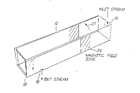
Fig. 2 is a perspective view of the tundish
shown in Fig. l;
Fig. 3 includes graphs of tracer concentration
at the tundish exit as a function of time for flow
control devices in the tundish and magnetic field
control;
Fig. 4 includes graphs of the percentage of
inclusion particles removed as a function of particle
rising velocity; and
1 334337
Fig. 5 shows a schematic sketch of the computed
maximum centerline velocity for a shallow (20 cm deep)
tundish, in the presence and in the absence of a
transverse magnetic field.
Description of the Preferred Embodiment
With reference first to Fig. 1, molten metal
such as steel is poured from a ladle 10 through a
tundish 12 into molds 14 where solidification takes
place. As shown in Figs. 1 and 2, the tundish 12 is a
relatively shallow trough (typically about 4-8 meters
long, a meter wide and a meter deep), into which molten
steel is poured at an inlet portion 16 and withdrawn at
outlet portions 18. The tundish 12 may have angled
walls 20. Tundishes such as the tundish 12 may also
include internal flow control devices such as weirs and
dams (not shown).
According to the invention, magnetic poles 22
and 24 flank the tundish 12 to generate a steady
magnetic field zone 26 across the tundish. The magnetic
field, preferably generated by electromagnets, has a
strength in the range of 500-50,000 Gauss. The magnetic
field in the magnetic field zone 26 is approximately
perpendicular to the principal direction of the molten
metal flow from the inlet portion 16 to the exit portion
18. The magnetic field direction is shown by an arrow
27. As will be appreciated by those skilled in the art,
as the metal flows through the magnetic field zone 26,
currents will be induced in the metal. These currents
generate their own magnetic field which interacts with
the externally applied field to result in a braking
force opposing the motion of the molten metal. The
application of the magnetic field thus tends to slow
down and streamline the flow through the tundish 12.
~ 5 - ~ 334~37
Similar arguments would apply to shallow
tundishes, such as used in novel continuous casting
processes for steel ferrous alloys and superalloys and
in the processing of non-ferrous metals, such as copper,
5 aluminum-or their alloys. Here again a steady magnetic
field would be applied in a direction perpendicular to
the principal flow direction, by placing magnets or
electromagnets close to the vertical walls.
Fluid flow phenomena in the tundish 12 have
10 been mathematically modeled by the applicants herein at
the Massachusetts Institute of Technology. The
controlling turbulent Navier-Stokes equations were
solved utilizing the PHOENICS computational code. See,
D.B. Spalding, "Mathematics and Computers in
15 Simulation", XIII, 267-276 (1981).
Fig. 3 illustrates one result of the simulation
showing tracer concentration Cex at the tundish outlet
as a function of time for various tundish
configurations. A curve 30 shows the results of the
20 simulation with the application of a 3,000 gauss
magnetic field. Note that the peak in tracer
concentration of the curve 30 is significantly shifted
in time with respect to the other curves representing
tundishes with internal flow control devices
25 illustrating the efficiency of the magnetic streamlining.
Fig. 4 shows yet another result of the
simulation. In Fig. 4, the percentage of inclusion
particles removed is plotted against inclusion particle
rising velocity UT. The lowermost scale in Fig. 4 is
30 inclusion particle diameter which is proportional to
rising velocity. A curve 32 in Fig. 4 is the result of
the simulation with a magnetic field of 3,000 gauss.
Note that the curve 32 indicates a very significant
- 6 - 1 3 3 ~ 3 3 7
improvement in the percentage of inclusion particles
removed as compared with other tundish flow control
techniques. The present invention improves the quality
of the resulting metal product in that higher
5 percentages of inclusion particles are removed while the
molten metal is in the tundish.
Fig. 5 shows the computed maximum centerline
velocities for a shallow tundish, 20 cm deep, 50 cm wide
and 1 meter long. It is seen that in the absence of a
10 magnetic field there is a very large variation in the
centerline velocity as we proceed from the inlet to the
exit, with a correspondingly large lateral spread in the
local velocities throughout the vessel.
In contrast, through the imposition of a
15 magnetic field of 3,000 Gauss, the centerline velocity
will be made rather uniform.
Although this disclosure has used stee' as the
exemplary metal, it will be appreciated by those skilled
in the art that the present techniques are applicable to
the casting of other metals. It is further recognized
that modifications and variations of the invention
disclosed herein will occur to those skilled in the art
and it is intended that all such modifications and
variations be included within the scope of the appended
25 claims.
What is claimed is: